Electrical wiring in the house
Before connecting the generator to the house, I analyzed the state of the house network. After the meter I had two 25A machines. I decided to immediately change them, since the wiring in the house is old.
I have many articles on choosing a circuit breaker, here is the main one. Here, in relation to the apartment.
Counter and circuit breakers. Third, IEK is not connected.
The PVS cable that goes up goes to the summer kitchen. It was decided to install the generator near the summer kitchen, under a canopy, so power from the generator will come through this cable.
Gas generator connection single and three-phase
The connection diagram for a three-phase power generator to a house or dacha in the presence of the same network implies similar connections as with a single-phase system. The only peculiarity: it is necessary to make more connections, since in this case the number of wiring strands is increased.
There is an important nuance: if you use a starter, then its contacts are intended for power wires, they will not be enough for the coil, you need to decide where to get the power for it.
Connecting a single-phase generator to the same network does not have the described complexity - there is only one phase, such a question simply does not arise. With three phases - L1, L2 and L3 - everything is more complicated. The solution is briefly simple: for the control circuit it is permissible to take any of the phases, but only one. For example, if the KM1 coil is powered from L3, then the control for the remaining starters, the start/stop keys, is also “hung” only on it. This is easy to do: mark with a marker or remember the color of the wire with the desired phase
We will consider phase mismatch briefly, since this is a separate topic. Connecting a three-phase gas generator to a single-phase network is possible, for example, using one of the power cores and a working zero. But the power is reduced by 3 times, and gasoline is consumed as usual. And if you separate 3 single-phase connections, phase imbalance may occur. Therefore, more complex schemes are used.
Connecting a single-phase generator to a three-phase home network is also possible. There are many schemes, but the simplest is this: parallel combination of 3 phases and connection to 1 phase of the power plant. At each phase the load will be distributed evenly.
Selection guide: you definitely need to buy a three-phase generator if the house has one and three-phase consumers at the same time, which often happens in private housing. Usually the product has a 380 V and a 220 V socket, that is, it can simultaneously power two types of devices.
Grounding
It is necessary to ground the backup source - a static charge arises on the case. It will be necessary to construct a separate grounding loop. It is ideal if it is possible to create a full-fledged structure, but a simple method is also suitable. You will need a metal rod 1.5–2 m, a bolt or clamp (metal), soft copper wire (large cross-section from 4 mm²). The core is connected with a clamp to the pin. Or they weld a bolt and attach it to it. The rod is driven into the ground, the other end of the wire is fixed to the generator housing.
So, the presented diagrams will help the user decide whether it is worth assembling autostart systems, buying an automatic transfer system, or getting by with manual start.
How to connect a generator
I didn’t want to connect the generator through the ATS circuit, because I don’t have the knowledge or funds for this, but I decided to do everything myself and connect it without automation.
The store advised me to connect the generator directly through the outlet, but I did not do so for safety reasons. And they offered and sold me this adapter:
Cable with plugs for connecting the generator to an outlet
To make using the generator safer, I made the following socket for it on the wall of the summer kitchen:
Generator socket
The SSI-114 type socket has a cover that protects live parts. But there will always be voltage on it - both when the generator is running and from the street! I secured it higher so that the children couldn’t reach it.
I made another adapter for connection so as not to confuse it with anything else, and signed the danger warnings.
Connection cable
The fork looks like this:
Generator output plug
This is the most dangerous place in the structure. But how to avoid trouble is the secret in the connection sequence, more on that later.
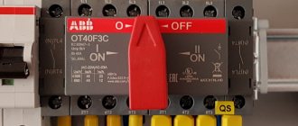
How to use a changeover switch correctly
When using this method, a connection to a distribution machine is also used. The input wiring is not disconnected. A three-position switch is mounted next to the machine. Thanks to this, there is no need to unscrew the wiring. The switch helps to switch the network power from the branches.
There is a zero in the generator, so three-terminal switches are not used for this method. It can be replaced using 2-band automatic machines in the amount of two pieces. They must be rotatable. There are holes on the case that allow you to fasten the keys. Strong and reliable pins are used for installation. During operation, a combination of buttons can block the power and break the circuit. In this case, a path is opened for the electric current that appears as a result of the operation of the unit. When pressed and triggered in a different sequence, the power line is opened and the energy is blocked.
Switches are installed next to the device. The launch is carried out in the following sequence:
• starting the engine and starting its work;
• warming up;
• appearance and gradual increase in load.
Experts recommend making connections nearby for the convenience of users. This rule will help prevent the generator from running unnecessarily when voltage is restored. To minimize the cost of operating the device without much benefit, you can connect an incandescent lamp. When the electric current transition is switched on, it will light up.
Input rework
The voltage from the street after the meter enters the house through a two-pole circuit breaker No. 1, and then through circuit breakers No. 2 and No. 3.
And the voltage from the generator is through machine No. 2.
The most important thing is that when the generator is running, machine No. 1 must be turned off!
What happens if you turn on the generator without turning off the input circuit breaker? In the best case, the circuit breakers will work, in the worst case, the generator will burn out, and/or the electrician of the repair team will receive a voltage shock from Victor’s generator!
It turns out that the generator is now connected to a special outlet on the wall of the summer kitchen. When the generator operates, the voltage goes to the summer kitchen, and then to machine 2, and then to machine 3 and into the house.
New circuit breakers installed
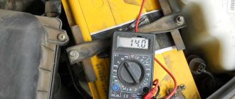
In the middle there is a 220V indicator, which is connected BEFORE the input machine, immediately after the meter. Thus, even during the day, I can immediately find out that there is light on the street, turn off the generator, and connect power from the street with automatic 1.
Connecting machines
The result is this nice design:
Electrical panel with meter and machines
Automatic generator start via AVR unit
The purpose of such devices is to partially or completely eliminate human participation in the operation of the generator. There are two main types of such devices. The first completely copies the auto-switching system, which operates on two starters, but with the addition of an electronic unit for starting and stopping the generator.
A low-current cable is connected to it from the main power supply line, through which the unit receives information about the presence or absence of voltage in the network. Depending on this, it sends a command to the engine to start or stop, and switching between input from the main line or from the generator is performed by the starters themselves. In general, this is the same system as the proposed scheme for self-assembly, but here you don’t have to invent anything - just install a ready-made unit.
The disadvantage of such a block is the same - its purpose is only to start and stop the engine without additional protection.
The diagram itself looks like this:
1. Introductory machine. 2. Electricity meter. 3. Automatic generator start block. 4. Generator. 5. Time relay. 6. RCD. 7. Main input contactor. 8. Backup input contactor.
A more advanced option is a complex system controlled by microprocessor electronics. In general, it works in the same way as a homemade autostart system, but its main advantage is the presence of numerous sensors that monitor all aspects of the generator's operation. If any equipment malfunction occurs, the ATS unit will be able to react adequately - not torment the generator with autostart attempts, but if there is a GSM module, send a message to the owner about the malfunction.
The ATS unit itself is mounted instead of a distribution panel - this does not require much knowledge - you just need to connect wires from the main line, power and control cables from the generator and output to the house to it.
1. Introductory machine. 2. Electricity meter. 3. AVR. 4.Generator. 5. Control cable. 6. Consumer machines. 7. Zero bus. 8. Grounding bus.
Such a unit is a complex set of equipment and its cost in some cases can be equal to the price of a generator. Therefore, its purchase is justified only in case of frequent power outages and for sufficiently powerful generators.
Generator switching sequence
The main secret of safety is in following these simple rules for turning on the generator. I hung them in front of the counter so I wouldn't forget. Besides, I may not be at home, my wife will turn on)
If there is no light from the street
1. Turn off ENTER (automatic 1)
2. Go to the generator, connect it to a special outlet.
3. Check that the load switch on the generator is turned off. Also, make sure that all heavy loads in the house are turned off.
4. Start the generator, let it warm up and go into operation for at least 30 seconds.
5. Turn on the machine on the generator.
6. Turn on the required load one by one.
If the light was given
1. The appearance of voltage on the street line is indicated by a red indicator under the meter.
2. Turn off the powerful load
3. Turn off the generator, turn off the load switch at its output.
4. Pull the generator plug out of the socket.
5. Turn on the introductory machine No. 1.
All this is done automatically by the ATS system; a person only needs to pull the starter on the generator. And if the generator has automatic start, you don’t need to do anything at all!
Organization and device of automated switching
In order not to switch the switch manually in the absence of electrical energy supply, you need to take care of implementing a simple circuit. It will allow you to start a gasoline generator automatically in order to switch from an external network to an autonomous one.
For installation, you will need to purchase two starting devices or contactors. They have cross switching. When they start to work, power and closed contacts are activated. They are required to provide time for the unit to warm up. For this purpose, a relay with a timer is purchased.
When the energy disappears, the power contacts are disconnected. At this time, the closed ones stop touching. Users can independently set the optimal time for the coil to be energized and the backup input to open. After this, the power contacts on the starter, which is intended for backup, are closed. At this time, electric current is supplied from the gasoline generator to the home network.
When the centralized power supply to a private house is resumed, the main starter coil will operate. The power contacts close and the power from the generator is automatically turned off. The home owner must turn off the engine to stop the generation of electrical energy.
Generator photo
Here are a few photos of the inverter generator Elektropribor BEG-3100.
Gasoline tank. Level indicator and cover
Air intake filter
Fuel tap
Recoil starter
Oil fill
Switch Connection
The simplest way to connect a generator is using a switch. The switch operates in three positions. In the initial position, the object is connected to a centralized power grid, without the participation of a gas generator.
When the switch moves to the next position, the object is completely de-energized. The next time you turn the switch, the power to the home network switches to a backup source - a gas generator.
Keep in mind that if the total power of all consumers is 6 kilowatts, then the switch must support at least 30 Amps.
Generator circuit
Just in case, I provide a generator circuit and a drawing.
Electrical circuit of the inverter generator Electrical device BEG-3100
Assembly drawing and catalog of spare parts for inverter generator Electric device BEG-3100
The instructions for this generator can be easily downloaded on the Internet.
In conclusion - a photo of how potatoes are sold at our market)
The generator powers the stall and scales
Everything is simpler here, no connection diagram is needed).
Thank you all for your attention, please vote for me!
If you liked the article, you can vote for it here.
Electrical diagram VAZ-2107 carburetor
Electrical diagram of VAZ 2107, 21074 produced in 1988-2001 with generator 37.3701
- block headlights
- side direction indicators
- accumulator battery
- starter relay
- carburetor electro-pneumatic valve
- carburetor microswitch
- generator 37.3701
- gearmotors for headlight cleaners *
- Fan motor switch sensor
- engine cooling fan motor
- sound signals
- distributor
- spark plug
- starter
- coolant temperature gauge sensor
- engine compartment lamp
- low oil pressure warning sensor
- low brake fluid level indicator sensor
- windshield wiper motor
- carburetor electro-pneumatic valve control unit
- ignition coil
- headlight washer pump motor *
- windshield washer pump motor
- mounting block
- windshield wiper relay
- hazard warning and direction indicator relay
- brake light switch
- reverse light switch
- ignition relay
- ignition switch
- three lever switch
- hazard switch
- socket for portable lamp**
- heater fan switch
- additional resistor for the electric motor of the heater (stove)
- rear window heating indicator lamp
- low brake fluid level warning lamp
- signaling unit
- heater fan electric motor
- glove compartment lamp
- light switches on the front door pillars
- switches for warning lights of open front doors ***
- front door open warning lights ***
- connection block
- cigarette lighter
- watch
- instrument light switch
- diode for checking the serviceability of the low brake fluid level indicator lamp
- fuel level indicator
- fuel reserve indicator lamp
- speedometer
- turn signal indicator lamp
- carburetor choke indicator lamp
- battery charge indicator lamp
- carburetor choke warning switch
- instrument cluster
- econometrician
- light switches on the rear door pillars
- coolant temperature gauge
- tachometer
- parking brake indicator lamp ("handbrake")
- low oil pressure warning lamp
- high beam indicator lamp
- indicator lamp for turning on external lighting
- voltmeter
- parking brake indicator switch ("handbrake")
- outdoor light switch
- rear window heating switch with backlight
- rear fog light switch with on/off indicator *
- fog light circuit fuse
- lampshade ****
- tail lights
- level indicator and fuel reserve sensor
- connectors for connecting to the rear window heating element *
- license plate lights 2107
Wiring diagram VAZ-2107 carburetor - full view:
Video on connecting a generator
I’m posting a video in which a colleague explains in detail how to connect a generator to a house. I recommend it!
Finally, I will say that the manufacturer usually plays it safe, or simply does not want to get into someone else’s sphere. Therefore, all instructions for such generators state that they are intended only for powering portable loads. For example, a grinder and a hammer drill in an open field. But not for powering a house or apartment.
As always, I look forward to your opinion in the comments!
What generators can be installed on a VAZ 2105
The question of choosing a generator for a VAZ 2105 arises when the standard device is not capable of providing current to the consumers installed on the car. Today, many car owners equip their cars with powerful headlights, modern music and other devices that consume high current.
The use of an insufficiently powerful generator leads to undercharging of the battery, which subsequently negatively affects engine starting, especially in the cold season.
To equip your car with a more powerful source of electricity, you can install one of the following options:
- G-2107–3701010. The unit produces a current of 80 A and is quite capable of providing additional consumers with electricity;
- generator from VAZ 21214 with catalog number 9412.3701–03. The current produced by the device is 110 A. For installation, you will need to purchase additional fasteners (bracket, strip, bolts), as well as make minimal changes to the electrical part;
- product from VAZ 2110 for 80 A or higher current. For installation, a suitable mount is purchased.
One of the powerful options for generator sets that can be equipped with a VAZ 2105 is a device from a VAZ 2110
Comments and reviews
The circuit of a car generator is based on the principle of electromagnetic induction.
The ABP is connected in parallel with the generator.
Modern automatic control systems are produced for solutions, including the control of generators.
Manual switching to an electric generator is cheaper. Their purpose is to determine the time during which the winding must be connected to the network. Other recommendations You can connect the generator yourself.
See also: Checking the loop phase zero technique
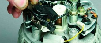
The rectifier consists of three pairs of diodes, which are installed on a conductive base and are combined in pairs with each other. Slip rings are used to power the winding.
Only if your backup station is low-power (up to 4 kW) can you connect it through an outlet. For many types of generator sets, the excitation winding has its own rectifier, assembled from 3 diodes.
Common mistakes
The opposite action with the keys will lead to the passage of current from the power line and blocking the flow of energy from the generator. The temperature of a working generator set can be up to 90 degrees, but if there is obvious overheating, the diode bridge should be diagnosed. From this moment on, the device provides the current necessary to power the load in the car and recharge the battery. Features of control, connection and fuel filling.
The starter turns on and the power plant starts working. Also, the car owner must remember a number of prohibitions, namely: Do not leave the car with the battery connected if there is a suspicion of a breakdown of the diode bridge. Modern automatic control systems are produced for solutions, including the control of generators. But as soon as the engine starts running, the generator produces current. Regulator relay. Wiring from scratch. Izh Jupiter/planet 4.5
Operating principle of AVR 02
How does the circuit assembled on the AVR-02 base work? Here are its main elements:
- KM1.1, KM2.1, KM3.1 are the power contacts of the starters
- KV1 – three-phase network monitoring relay
- contacts No. 18,19,20 – are intended for monitoring emergency circuits in motor drives
If a malfunction occurs in the motor drive, voltage is supplied to them and the relay operation is blocked.
- S1 is something like a button with which you can send a signal and forcefully block the operation of the AVR-02
Suddenly you need to carry out some commissioning work. Here you can use the modular option from IEK KMU11.
- SB1 – Reset button
Needed for reset after receiving a signal at contacts No. 18,19,20. Press it and the relay's operation is restored.
- KM4 – intermediate relay
Thanks to its contacts, voltage can be supplied to the coils both from two inputs and from the generator. You can use the RK-1R type.
Let's consider three work algorithms and three situations for this ATS.
Where should the station be located?
The room should be dry , with good ventilation. In addition, a very unpleasant hum emanates from the generator during operation. Taking these nuances into account, it is better to install and connect the electrical installation in a garage, outbuilding or under a canopy.
The electric generator is installed on a foundation that does not have a rigid connection with the building. You can place the device on special shock absorbers or on a rubber cushion. This helps reduce the sound of the generator.
Installing special noise-protective enclosures also helps reduce the hum.
Basic connection tasks
When installing electrical installations, the following indicators must be taken into account :
- need for automation;
- location in terms of efficiency and safety;
- stock selection;
- frequency of network outages;
- power consumption taking into account losses.
It is important to create a suitable connection diagram for a gasoline generator.
Automation of the process is expensive and requires qualified maintenance. Manual connection for a private home is the most gentle mode. Such switches are produced in two types: a changeover type switch (old model) or a reversible switch (three-way). You can find out more about them below. They also use partial automation, because semi-automatic machines are inexpensive. Regardless of the chosen method, you need to monitor the operation of the system.
The principle of operation of this device in tractor technology
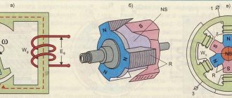
To be honest, it is no different at all, except for its appearance, dimensions (dimensions), connection methods and a few more nuances.
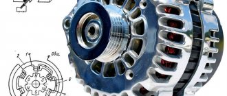
The MTZ - 80 generator is always a three-phase device with one-way excitation of the electromagnet, which is called G306 - D (other modifications: G - 306A, G - 304A).
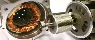
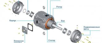
For adequate operation, the G306-D generator requires direct current, which is why in the generator itself the current passes through a three-phase rectifier, turning into direct from alternating. The main parts of the G306 - D, installed on Belarusian tractors of the MTZ brand - 80, 82 and similar models, are a static device and a rotary device (stator and rotor).
The stator of this model is made of several electrical steel sheets, and a three-phase coil with winding is attached from the inside to the protrusion. The rotor is made using a similar technology and looks like a star with six corners, pressed onto the shaft, where it is attached.
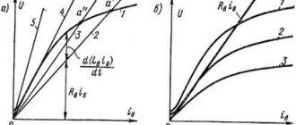
You can see a detailed diagram of the G306-D generator in the figure:
1 – Cover of the control device; 2 – Screw; 3 – Washer; 4 – Washer; 5 – Nut; 6- Washer; 7 – Washer; 8 – Nut; 9 – Washer; 10 – Washer; 11 – Insulating washer; 12 – Insulator; 13 – Rear cover; 14 – Output panel; 15 – Bolt M6x53; 16 – Rectifier; 17 – Spacer sleeve; 18 – Bolt M4x27.5; 19 – Phase insulator; 20 – Split bushing; 21 – Excitation coil; 22 – Coupling bolt; 23 – Ball bearing; 24 – Screw; 25 – Nut; 26 – Washer; 27 – Pulley (single-strand); 28 – Fan; 29 – Screw; 30 – Bearing cover; 31 – Ball bearing; 32 – Bolt; 33 – Front cover; 34 – Shield; 35 – Bolt; 36 – Washer; 37 – Rotor bushing; 38 – Nut; 39 – Washer; 40 – Washer; 41 – Bolt; 42 – Nut; 43 – Bolt; 44 – Generator bracket; 45 – Stretching; 46 – Rotor; 47 – Nut; 48 – Stator; 49 – Plank; 50 – Bolt; 51 – Thrust washer; 52 – Screw M8x28; 53 – Regulating device.
Connection diagram for the electrical circuit of the MTZ tractor - 80, 82 and its modifications:
AVR-02 reserve input unit
This device is multifunctional and can be used to build 8 different ATS circuits. Three of them are most often used:
- input#1+input#2
- input#1+generator
- input#1+input#2+generator
Let's first consider the most complex one, which has two inputs and a generator. The second input can be either from a separate 0.4 kV overhead line or directly from a cable line from the nearest transformer substation, or assembled on a battery-powered UPS with hybrid inverters.
In this case, in the version with an uninterruptible power supply, it is necessary to provide for a situation when the batteries are discharged to the permissible maximum, and then a switch to the generator occurs. This is very convenient so as not to run the diesel generator during short-term interruptions in the power supply.
What functionality does the AVR-02 have?
- it controls power elements - contactors or starters. Motor drives can also be used.
- controls phase rotation
- controls input synchronization
- generates a generator start signal
- Can be powered by external 12V battery
- measures the voltage level and turns off the faulty line with low or high voltage, automatically transferring power to the one where everything is normal
- generates an emergency signal
On the front panel of the AVR-02 there are:
- two-line liquid crystal display
- navigation buttons
- LED indicators No. 1 and No. 2 – show the connected input
- K1, K2, K3, K4 – state of the executive relays
Simple ATS circuit for 2 inputs
The simplest ATS circuit for two single-phase inputs is assembled on just one magnetic starter. To do this you will need a contactor with two pairs of contacts:
- normally open
- normally closed
If your contactor does not have these, you can use a special attachment.
Just keep in mind that the contacts of most of them are not designed for high currents. And if you decide to connect the load of the entire house through the ATS, then you certainly shouldn’t do this using the block contacts located on the sides of standard starters.
For these purposes, it is better to choose equipment that initially has power closed and open contacts in its design. Suitable brands are VS 463-33 or ESB-63-22, MK-103 from DeKraft, KM IEK.
Here is the simplest AVR diagram: