Control and protection equipment
Definition 1
Control and protection equipment is a set of devices used to control electrical networks and protect them.
Protection and control devices include:
- Fuse with fusible link. This device is used to protect the electrical circuit from overcurrents, overloads and short circuits. Its design is quite simple. The device body contains a wire made of metal with a low melting point and low resistivity. When overcurrent occurs, the temperature increases, which leads to the melting of the insert and the power supply is turned off.
- Circuit breaker. This device is used to protect wiring from overcurrents.
- Overcurrent relay. This device is used for the same purpose as a fusible link fuse. This device reacts to an increase in current in the protected electrical circuit; with its help, you can create maximum protection against overload and short circuit currents.
- Contactor. This device is used to remotely turn off or turn on electrical circuits whose power does not exceed 1000 Volts.
- Actuator. This device is used to safely remotely (using a button) turn on or turn off the power supply to installations. It is used in alternating current networks. The main working unit of the starter is an electromagnet. In addition to the main contact group, the device includes an auxiliary one.
- Delay relay. This device is used to create a time delay when other elements (devices) of the circuit are triggered. There are digital, semiconductor and electromagnetic delay relays.
- Thermal relay. This device is used to protect electrical equipment from overheating in the event of minor overloads of the asynchronous motor.
- Thyristor voltage regulator. This device is used to control the load current by controlling the firing angle of the thyristors.
- Magnetic amplifier. This device is used to increase load power with low control powers.
Are you an expert in this subject area? We invite you to become the author of the Directory Working Conditions
Definition 2
A thyristor is a semiconductor device that is made on the basis of a single crystal conductor with three or more p-n junctions, and also has two stable states: closed (low conductivity) and open (high conductivity).
Purpose of circuit breakers
A circuit breaker is an electromechanical device that ensures the flow of current in normal mode and automatically turns off the current (voltage) in emergency situations: short circuit and overload.
In addition to protection from emergency situations, circuit breakers are used to quickly turn off and turn on power for electrical networks. Simply put, circuit breakers are also switches for individual power lines or the power network as a whole.
Circuit breakers are designed to protect electrical wiring from short circuits and overloads. In case of overload or short circuit, circuit breakers turn off (de-energize) the electrical network in which they are installed. For this purpose, special release devices are built into them. Protects against overload, thermal release. Disconnect the electromagnetic one from a short circuit (read about the design of circuit breakers below).
Selection of control and protection equipment for electrical equipment of power supply facilities
The choice of protection and control equipment for electrical equipment of power supply facilities is carried out based on:
- Power supply parameters.
- Requirements for the protection of power supply facilities.
The design of electrical devices is calculated and marked at the manufacturer individually for each type of device (current value, voltage, and mode). Thus, one of the ways to select equipment comes down to searching for the desired device in the manufacturer’s catalog.
When choosing control and protection devices, it is necessary to take into account the possibility of abnormal operating modes: phase-to-frame short circuits, phase-to-phase short circuits, voltage drop or disappearance, electric current increase, etc.
Short circuit
A short circuit is an emergency connection of different functional wires of an electrical wiring. In apartments and houses, this is a mechanical contact of the phase (L) and neutral working (N) conductors or the phase wire (L) and the ground wire (PE) of an energized electrical network.
In electrical networks with a three-phase power supply of 380 volts, a short circuit is called the contact of any of those phase wires (L1, L2, L3) with each other or the contact of any phase wire and the neutral working wire (N) or the phase wire and the protective conductor (PE).
A short circuit in the wires can lead to electrical failure or, at most, a fire. It is much more dangerous if the short circuit current passes through a person. This is quite possible if you accidentally touch a phase wire under load.
To protect against short circuits in electrical networks, circuit breakers with an electromagnetic release are designed.
Overload
The entire electrical network of the room is divided into groups. Each group is designed for a certain number of consumers. For example: if this is an apartment, then there may be separate groups for lighting, sockets in the kitchen, sockets in the rooms, etc. If electrical wiring is done independently, then the number of groups is calculated depending on the needs and may be different for each individual case. In standard apartments, the number of groups corresponds to the apartment design. The maximum possible load is calculated for each group. Depending on the load, the power cable for this group is selected.
An increase in the design load is called network congestion. An overload occurs if, for example, you thoughtlessly turn on all household appliances in the sockets of one group. As the design load increases, the electrical cable begins to heat up. With prolonged overload, the insulation will begin to melt, which can lead to fires or burnout of the wiring.
To protect electrical wiring from overload, circuit breakers with a built-in thermal release (bimetallic plate) are installed.
How does a machine operate in short circuit mode?
In the event of a short circuit, the operating principle of the circuit breaker is different. During a short circuit, the current in the circuit increases sharply and many times to values that can melt the wiring, or rather the insulation of the electrical wiring. In order to prevent such a development of events, it is necessary to immediately break the chain. This is exactly how an electromagnetic release works.
It will be interesting➡ Voltage control relay
The electromagnetic release is a solenoid coil containing a steel core held in a fixed position by a spring.
A multiple increase in the current in the solenoid winding, which occurs during a short circuit in the circuit, leads to a proportional increase in the magnetic flux, under the influence of which the core is drawn into the solenoid coil, overcoming the resistance of the spring, and presses the release bar of the release mechanism. The power contacts of the machine open, interrupting the power supply to the emergency section of the circuit.
Thus, the operation of the electromagnetic release protects the electrical wiring, the closed electrical appliance and the machine itself from fire and destruction. Its response time is about 0.02 seconds, and the electrical wiring does not have time to warm up to dangerous temperatures.
At the moment the power contacts of the machine open, when a large current passes through them, an electric arc appears between them, the temperature of which can reach 3000 degrees.
To protect the contacts and other parts of the machine from the destructive effects of this arc, an arc-extinguishing chamber is provided in the design of the machine. The arc chamber is a grid of a set of metal plates that are insulated from each other.
The arc occurs at the point where the contact opens, and then one of its ends moves along with the movable contact, and the second slides first along the fixed contact, and then along the conductor connected to it, leading to the rear wall of the arc-extinguishing chamber.
There it divides (splits) on the plates of the arc-extinguishing chamber, weakens and goes out. At the bottom of the machine there are special openings for the removal of gases formed during arc combustion.
If the machine turns off when the electromagnetic release is triggered, you will not be able to use electricity until you find and eliminate the cause of the short circuit. Most likely the cause is a malfunction of one of the consumers.
Disconnect all consumers and try to turn on the machine. If you succeed and the machine does not kick out, it means that one of the consumers is indeed to blame and you just have to find out which one. If the machine breaks down again even with the consumers disconnected, then everything is much more complicated, and we are dealing with a breakdown of the wiring insulation. We'll have to look for where this happened.
This is the principle of operation of a circuit breaker in various emergency situations.
If tripping your circuit breaker has become a constant problem for you, do not try to solve it by installing a circuit breaker with a higher rated current.
The machines are installed taking into account the cross-section of your wiring, and, therefore, more current in your network is simply not allowed. A solution to the problem can only be found after a complete inspection of your home’s electrical system by professionals.
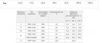
Selection of machine by power (table)
Let’s say right away that there are several ways. The simplest is to calculate the machine’s power using one of the online calculators. But no matter which one you choose, first of all you need to determine the total load on the network. How to calculate this indicator? To do this, you will have to deal with all the household appliances that are installed on the power supply section.
It is more convenient to calculate the machine by power, rather than select the machine by current. In order not to be unfounded, we will give an example of a network into which a large number of household appliances are usually connected. It's a kitchen.
- So, in the kitchen there is usually:
- Refrigerator with power consumption of 500 W.
- Microwave oven – 1 kW.
- Electric kettle – 1.5 kW.
- Hood – 100 W.
It will be interesting➡ Electromagnetic radiation is an invisible killer.
This is almost a standard set, which can be a little larger or a little smaller. Adding up all these indicators, we get the total power of the site, which is equal to 3.1 kW. And now here are the methods for determining the load and the choice of machine itself.
To increase safety, electrical wiring in the apartment should be divided into several lines. These are separate machines for lighting, kitchen sockets, and other sockets. High-power household appliances with increased danger (electric water heaters, washing machines, electric stoves) must be turned on through an RCD.
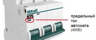
The RCD will respond in time to a current leak and turn off the load. To choose the right machine, it is important to consider three main parameters; - rated current, switching capacity of short-circuit current interruption and class of circuit breakers.
The calculated rated current of the machine is the maximum current that is designed for long-term operation of the machine. When the current is higher than the rated one, the contacts of the machine are disconnected. The class of machines means a short-term value of the starting current when the machine has not yet triggered.
The starting current is many times greater than the rated current value. All classes of machines have different starting current levels.
- There are 3 classes in total for machines of various brands:
- class B, where the starting current can be 3 to 5 times greater than the rated current;
- class C has an excess of the nominal current by 5 - 10 times;
- class D with possible excess current of the rated value from 10 to 50 times.
In houses and apartments, class C is used. The switching capacity determines the magnitude of the short circuit current when the machine is instantly turned off. We use circuit breakers with a switching capacity of 4500 amperes; foreign circuit breakers have a short-circuit current. 6000 amps You can use both types of machines, Russian and foreign.
Tabular method
How to choose a machine by power table. This is the easiest option for choosing the right circuit breaker. To do this, you will need a table in which you can select a machine (single- or three-phase) based on the total indicator.
Selection of machine by power:
Connection type Single-phase Single-phase input Three-phase delta Three-phase star
| Machine polarity | Single-pole circuit breaker | Two-pole machine | Three-pole machine | Four-pole circuit breaker |
| Supply voltage | 220 volt | 220 volt | 380 Volt | 220 volt |
| Automatic 1A | 0.2 kW | 0.2 kW | 1.1 kW | 0.7 kW |
| Automatic 2A | 0.4 kW | 0.4 kW | 2.3 kW | 1.3 kW |
| Automatic 3A | 0.7 kW | 0.7 kW | 3.4 kW | 2.0 kW |
| Automatic 6A | 1.3 kW | 1.3 kW | 6.8 kW | 4.0 kW |
| Automatic 10A | 2.2 kW | 2.2 kW | 11.4 kW | 6.6 kW |
| Automatic 16A | 3.5 kW | 3.5 kW | 18.2 kW | 10.6 kW |
| Automatic 20A | 4.4 kW | 4.4 kW | 22.8 kW | 13.2 kW |
| Automatic 25A | 5.5 kW | 5.5 kW | 28.5 kW | 16.5 kW |
| Automatic 32A | 7.0 kW | 7.0 kW | 36.5 kW | 21.1 kW |
| Automatic 40A | 8.8 kW | 8.8 kW | 45.6 kW | 26.4 kW |
| Automatic 50A | 11 kW | 11 kW | 57 kW | 33 kW |
| Automatic 63A | 13.9 kW | 13.9 kW | 71.8 kW | 41.6 kW |
Everything is quite simple here. Most importantly, you need to understand that the calculated total power may not be the same as in the table. Therefore, the calculated indicator will have to be increased to the tabular one.
From our example it can be seen that the power consumption of the site is 3.1 kW. There is no such indicator in the table, so we take the nearest larger one. And this is 3.5 kW, which corresponds to a 16-amp machine.
As we can see from the table, the calculation of a machine with a power of 380 differs from the calculation of a machine with a power of 220.
Graphic method
This is practically the same as the tabular one. Only instead of a table, a graph is used here. They are also freely available on the Internet. As an example, we give one of these.
On the graph, circuit breakers with current load indicator are located horizontally, and the power consumption of the network section is located vertically.
To determine the power of the circuit breaker, you must first find the calculated power consumption on the vertical axis, and then draw a horizontal line from it to the green column that determines the rated current of the machine.
You can do this yourself with our example, which shows that our calculation and selection was done correctly. That is, this power corresponds to a machine with a load of 16A.
Nuances of choice
Today it is necessary to take into account the fact that the number of convenient household appliances is limited, and every person tries to acquire new devices, thereby making their life easier.
This means that by increasing the number of equipment, we increase the load on the network. Therefore, experts recommend using a multiplying factor when calculating the power of the machine.
Let's return to our example. Imagine that the owner of the apartment purchased a 1.5 kW coffee machine. Accordingly, the total power indicator will be equal to 4.6 kW. Of course, this is more power than the circuit breaker we selected (16A). And if all the devices are turned on at the same time (plus the coffee machine), the machine will immediately reset and disconnect the circuit.
You can recalculate all the indicators, buy a new machine and reinstall it. In principle, this is all easy. But it will be optimal if you foresee this situation in advance, especially since it is standard these days.
It is difficult to predict exactly what additional household appliances can be installed. Therefore, the simplest option is to increase the total calculated indicator by 50%. That is, use a multiplying factor of 1.5. Let's go back to our example again, where the end result will be like this:
3.1x1.5=4.65 kW. Let's return to one of the methods for determining the current load, in which it will be shown that for such an indicator you will need a 25 ampere machine.
For some cases, a reduction factor can be used. For example, there is not enough sockets for all devices to work simultaneously. This could be one socket for an electric kettle and a coffee machine. That is, it is not possible to turn on these two devices at the same time.
When it comes to increasing the current load on a network section, it is necessary to change not only the machine, but also check whether the electrical wiring can withstand the load, for which the cross-section of the laid wires is considered. If the cross-section does not meet the standards, then it is better to change the wiring.
Calculation of the machine according to the cross-section of the electrical wiring
To select a machine, you can use the table. The current selected for the cross-section of the electrical wiring is reduced to the lower current value of the machine to reduce the load on the electrical wiring.
Load power depending on the rated current of the circuit breaker and cable cross-section
Cable cross-section, sq. mm Rated current of the machine, A Power of 1-phase load at 220 V, kW Power of 3-phase load at 380 V, kW
| Copper | Aluminum | |||
| 1 | 2.5 | 6 | 1.3 | 3.2 |
| 1.5 | 2.5 | 10 | 2.2 | 5.3 |
| 1.5 | 2.5 | 16 | 3.5 | 8.4 |
| 2.5 | 4 | 20 | 4.4 | 10.5 |
| 4 | 6 | 25 | 5.5 | 13.2 |
| 6 | 10 | 32 | 7 | 16.8 |
| 10 | 16 | 40 | 8.8 | 21.1 |
| 10 | 16 | 50 | 11 | 26.3 |
| 16 | 25 | 63 | 13.9 | 33.2 |
It will be interesting➡ How to take measurements with a megohmmeter
For sockets, the machines take a current of 16 amperes, since the sockets are designed for a current of 16 amperes; for lighting, the optimal version of the machine is 10 amperes. If you do not know the cross-section of the electrical wiring, then it is easy to calculate it using the formula:
- Where:
- S – wire cross-section in mm²;
- D is the diameter of the wire without insulation in mm.
The cross-sectional method of calculating a circuit breaker is more preferable, as it protects the electrical wiring in the room.