15 591
Burykin Valery Ivanovich
Current generator
and
a voltage generator
. What is the difference? What is a Current Generator and what are its areas of application.
***
For work, it was necessary to find some clear description of what a current generator is (current stabilizer, current source)
, its areas of application and calculation examples. We couldn't find anything acceptable.
I had to start writing an article answering these questions myself.
And yet, we had to replace the generally accepted designations “delta” and “infinity” with words. Unfortunately, instead of them, when you try to read the text, question marks are displayed.
02/28/2012
***
The first thing we need to understand is what the differences are between a current generator and a voltage stabilizer.
What are current sources
Current sources are elements of an electrical circuit that support energy with given parameters. At the same time, the energy supply of the circuit does not depend on the characteristics of the elements included in its composition, in particular, resistance.
Device for generating current
There are ideal and real devices for generating current:
- Ideal ones are determined only thanks to hypotheses and theoretical calculations. Thus, scientists often determine a number of conditions under which the current has maximum values close to ideal. That is, an imitation of an ideal source is carried out.
- Real-life conditions support the specified output current and voltage parameters. Any device ensures its operation, provided that its technical characteristics allow it to do so.
Important! Thus, the maximum value of current and voltage make it possible to determine which version of the source will be used in the circuit - ideal or real.
Voltage regulator.
Other names:
— voltage source;
— voltage generator;
— reference voltage source (in circuits it is usually designated as ION).
Basic requirement:
Uout. = const.
Load current
connected to the output of the voltage stabilizer
changes
depending on the value of Rload.
The ideal operating mode of the voltage stabilizer corresponds to Rload. = infinity.
Ideal voltage generator
creates
stable voltage In this case, its internal resistance is zero (Ru = 0). The load current is determined by the formula:
Iload = U / Rload.
From this we can conclude:
- since the voltage is stable, then when Rload changes. the current flowing through the load will change, Fig. 1.
Rice. 1 Diagram of an ideal voltage source.
Ideal voltage source when reducing Rload. to zero is capable of creating a current of infinitely large magnitude.
But nothing ideal exists in life; all voltage sources have some internal resistance - Ru.
This leads to the fact that the source voltage is divided between the internal resistance Ru and the load resistance Rload, Fig. 2
Rice. 2 Functional diagram of a real voltage source.
Therefore, the load current is calculated using the formula:
Iload = U / (Ru + Rload)
The maximum current occurs at Rload. = 0.
It is clear from the formula that the current in the load depends on the voltage developed by the source, as well as on the value of the sum of resistances Rload. and Ru.
As a rule, the internal resistance of the voltage source (Ru) is selected at least 100 times less than the minimum possible
load resistance values (Rload min). In this case, the voltage at the source output when the load resistance changes from infinity to Rload. min will change by no more than 1%.
Those. It is desirable that the following condition be met:
Rload min => 100*Ru
In this case, we do not consider the issue of the power of the voltage source. The power depends on the principle of construction of the source, the implemented circuit and the components used.
Now let's see what a current generator is
Types of sources
There are several types of devices for generating current, each of which has its own main indicators, characteristics and features, listed in the following table:
| Source type | Current source characteristics |
| Mechanical | A special device (generator) ensures the transformation of mechanical energy into electrical energy. Currently, a large amount of current is produced using mechanical sources. |
| Thermal | The operation of the units is based on the principle of converting thermal energy into electrical energy. This transformation occurs due to the temperature difference between the semiconductors in contact with each other. Currently, current sources have been developed in which thermal energy is generated due to the decay of radioactive elements. |
| Chemical | Chemical options can be divided into 3 groups - galvanic, batteries and thermal. · A galvanic cell works through the interaction of 2 different metals placed in an electrolyte. · Batteries are devices that can be charged and discharged several times. There are several types of batteries with different types of cells included in their composition. · Chemical-thermal ones are used only for short-term work. They are mainly used in the field of rocketry. |
| Light | At the end of the 20th century, solar panels became quite popular, which “collect” light particles, which are subsequently converted into electrical energy. This occurs due to the output of voltage and due to the effect on light particles. |
You might be interested in how electric current affects the human body.
Important! Each type has its own advantages and disadvantages, which are determined by the principle of use, as well as the initial indicators of the generated energy.
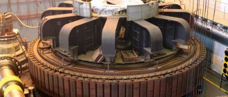
Mechanical sources
Mechanical units are the simplest in terms of their use and arrangement. The characteristics of such generators are very easy to understand. Special devices generate energy, which is subsequently converted into electricity. Such devices are used in thermal power plants and hydroelectric power plants.
Mechanical
Heat sources
Thermal source options provide a unique operating principle. Energy is generated through the formation of a thermocouple, which... This means that a calculated temperature difference is provided at the ends of the conductors, the elements interact with each other, creating an electric field.
Thermal
Note ! Radioactive thermocouples are used in the space industry. The effectiveness of such use is possible due to the long service life and efficient power output.
As a result of this movement of charged particles from the hot part of the conductor to the cold part, an electric current arises. Moreover, the greater the temperature difference, the higher the effective energy indicator. In practice, thermocouples are often included in measuring instruments.
Light sources
Lighting devices for generating electricity are considered the most environmentally friendly, efficient and relatively cheap. A special panel of semiconductors absorbs light particles, which during such interaction produce a certain voltage.
Light
At the same time, light panels have a low efficiency rate of 15%. Panels of this type have found wide application - from household appliances to innovative developments in the space industry.
Important! Light sources began to be used instead of lithium batteries due to the high cost of the latter. Despite the fact that many industrial facilities require significant re-equipment to switch to light sources, the final savings occur already in the initial stages of operation.
Chemical sources
This group includes 3 main devices that differ in structure and operating principle:
- A voltaic cell is an option for generating electricity that can be used once. That is, after complete discharge, re-accumulation of charge on the internal substance is impossible. Such devices include salt, lithium or alkaline batteries.
- Batteries are divided into several types: lead-acid, lithium-ion, nickel-cadmium.
- Thermal elements - used in the space and innovation industries to produce short-term current with high performance. The practical application of the units is based on the need for backup power sources.
You might be interested in this: Features of SMD markings
Important! Chemical-thermal devices require initial heating to 500–600 °C to activate the solid electrolyte.
Chemical
Each industry uses its own version with specific parameters. In domestic conditions, batteries are mainly used; in production - batteries.
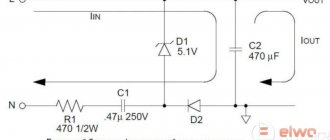
Analog DC Source Circuit
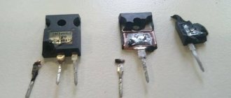
Since this is a direct current source, that is, a kind of electronic load, it is adapted to work with a low-current independent 12 V power supply. The power part of the circuit is an available high-power MOSFET IRF3205, treated as a variable resistor. Note that a power FET can also be used in linear (rather than switching) mode, in which case it is usually treated as a variable resistor.
The next key element in this circuit is the TL431A three-pin programmable shunt regulator diode. There is also a low-power dual operational amplifier chip - LM358.
Designation of current sources
So that when choosing there is no question as to what type of current source is presented, special designations are used. In physics, there are precise graphical representations that allow you to identify the type of source used:
Designations
On each symbol chart you can see the following parameters:
- General designation of the current source and the driving force of the EMF;
- Graphic image without EMF;
- Chemical type;
- Battery;
- Constant pressure;
- AC voltage;
- Generator.
Thanks to graphic identifiers on an electrical circuit diagram, you can always determine which type is used in a particular situation and how to correctly designate it. There are also international designations, which are found a little less frequently, usually when implementing international projects.
Chemical voltage sources.
The next most important method of generating electrical energy is the use of chemical batteries. A battery consists of two electrodes made of dissimilar metals (for example, copper and zinc) and immersed in an electrolyte (acid, alkali or salt solution). They create contact between the circuit and the electrolyte. Free electrons are extracted from the copper electrode using an electrolyte, and the zinc electrode attracts these electrons. Thus, the copper electrode has a positive charge, and the zinc electrode has a negative charge. Several of these elements combine together to form a battery. Some examples of chemical voltage sources are presented in Figure 3.4.
Figure 3.4. Chemical voltage sources
Figure 3.5 shows the graphical symbols of a chemical element and a battery of chemical elements.
Figure 3.5. UGO a) chemical element; b) bateria.
Operating principle
Each marking of current sources determines the principle of its operation. In a standard situation, energy is generated through the interaction of component parts, namely:
- Mechanical type. As a result of the interaction of mechanism parts, friction occurs. Due to this phenomenon, static electricity arises and is converted into current.
- Mechanical structures work by producing sequentially moving charged particles. The phenomenon occurs due to the interaction of a chemical element with an electrolyte. Charged particles leave the structure of the metal crystal lattice, becoming part of the conducting liquid.
- Solar batteries (light sources) work by knocking out charged particles from a dielectric (silicon) base under the influence of a light flux. This creates constant tension.
- Thermal. As a rule, these are 2 metal bases connected in series. One part heats up, while the other remains cooled. When the temperature regime changes, a temperature difference occurs, resulting in the movement of charged particles.
You might be interested in Features of calculating power by current and voltage
Important! Any change in the structure of a substance can lead to irreversible consequences that will manifest themselves during the operation of the device.
Design
The design of the element affects the principle of its operation. Each source that produces electric current has a specific design:
- The simplest household battery includes a metal case, inside of which an alkaline environment is used. Additional elements are lead plates on which cathodes and anodes are accumulated.
Battery
- An ordinary household battery with a dry cell included in its composition has a metal case in which a cathode storage rod is placed. All other space is filled with salt electrolyte.
Battery
- An alternator is a device consisting of ratchets or a metal frame.
Mechanical principle of the device
- A thermal current source that is already included in the circuit. This is a regular frame mounted on a dielectric stand. Typically, the structure is connected to a measuring device, such as an ammeter. The heat source is a flame or an external electrical impulse.
Thermal device
Important! This design helps to understand exactly how energy is generated, which is subsequently converted into current. Each design option is usually enclosed in a special housing made of dielectric material.
Designations in graphic diagrams. Part 2
For convenience, use the search, this is the key combination Ctr+F
Table 6(d):
| Name | Designation |
| 1. Direct current, basic designation | |
| Note. If it is impossible to use the basic designation, then use the following designation | |
| 2. Direct current polarity: a) positive | |
| b) negative | |
| 3. m DC wire line with voltage U, for example: | |
| a) two-wire 110 V DC line | |
| b) three-wire DC line, including the middle wire, with a voltage of 110 V between each outer conductor and the middle wire 220 V - between the outer conductors | |
| 4. Alternating current, basic designation | |
| Note. It is allowed to indicate the frequency value to the right of the designation of alternating current, for example alternating current with a frequency of 10 kHz | |
| 5. Alternating current with the number of phases m, frequency f, for example, three-phase alternating current with a frequency of 50 Hz | |
| 6. Alternating current with number of phases m, frequency f, voltage U, for example: | |
| a) alternating current, three-phase, frequency 50 Hz, voltage 220 V | |
| b) alternating current, three-phase, four-wire line (three wires, neutral) with a frequency of 50 Hz, voltage 220/380 V | |
| c) alternating current, three-phase, five-wire line (three phase wires, neutral, one protective wire with grounding) with a frequency of 50 Hz, voltage 220/380 V | |
| d) alternating current, three-phase, four-wire line (three phase wires, one protective wire with grounding, serving as a neutral) with a frequency of 50 Hz, voltage 220/380 V | |
| 7. AC frequencies (main designations): a) industrial | |
| b) sound | |
| c) ultrasonic and radio frequencies | |
| d) ultra-high | |
| 8. Direct and alternating current | |
| 9. Pulsating current |
Table 6 (d)
| Name | Designation |
| 1. Single-phase winding with two terminals | |
| 2. Single-phase winding with output from the middle point | |
| 3. Two single-phase windings, each with two terminals | |
| 4. Three single-phase windings, each with two terminals | |
| 5. m single-phase windings, each with two terminals | |
| 6. Two-phase winding with separate phases | |
| 7. Three-phase winding with separate phases | |
| 8. Multiphase winding n with the number of separate phases m. Note. to pp. 6-8. Designations are used for windings with separate phases, for which various methods of external connections are allowed | |
| 9. Two-phase three-wire winding | |
| 10. Two-phase four-wire winding | |
| 11. Two-three-phase winding of a T-shaped connection (Scott winding) | |
| 12. Three-phase winding V-shaped connection of two phases in an open delta | |
| Note. It is allowed to indicate the angle at which the windings are turned on, for example at angles of 60 and 120 degrees | |
| 13. Three-phase winding connected in a star | |
| 14. Three-phase winding connected in a star, with the neutral brought out | |
| 15. Three-phase winding connected in a star, with a grounded neutral brought out | |
| 16. Three-phase winding connected in a triangle | |
| 17. Three-phase winding connected in an open triangle | |
| 18. Three-phase winding connected in a zigzag | |
| 19. Three-phase winding connected in a zigzag, with the neutral brought out | |
| 20. Four-phase winding | |
| 21. Four-phase winding with output from the middle point | |
| 22. Six-phase winding connected in a star | |
| 23. Six-phase winding, connected in a star, with output from the middle point | |
| 24. Six-phase winding connected into a double star | |
| 25. Six-phase winding connected into two reverse stars | |
| 26. Six-phase winding connected into two reverse stars, with separate leads from the midpoints | |
| 27. Six-phase winding connected in two triangles | |
| 28. Six-phase winding connected in a hexagon | |
| 29. Six-phase winding connected in a double zigzag | |
| 30. Six-phase winding connected in a double zigzag, with output from the middle point |
Table 6(e)
| Name | Designation |
| 1. Rectangular pulse: a) positive | |
| b) negative | |
| 2. Trapezoidal pulse | |
| 3. Impulse with a steep decline | |
| 4. Pulse with a steep front | |
| 5. Bipolar impulse | |
| 6. Acute-angled impulse: a) positive | |
| b) negative | |
| 7. Acute-angled pulse with exponential decay | |
| 8. Sawtooth pulse: a) with linear increase | |
| b) with a linear decline | |
| 9. Harmonic impulse | |
| 10. Stepped impulse | |
| 11. High frequency pulse (radio pulse) | |
| 12. AC pulse | |
| 13. Distorted pulse Note. Qualifying symbols are simplified reproductions of the waveforms of the corresponding pulses. |
Table 6 (g)
| Name | Designation |
| 1. Analog signal | |
| 2. Digital signal | |
| 3. Positive signal level difference | |
| 4. Negative signal level difference | |
| 5. High signal level | |
| 6. Low signal level |
Table 6 (h)
| Name | Designation |
| 1. Amplitude modulation | |
| 2. Frequency modulation | |
| 3. Phase modulation | |
| 4. Pulse modulation: | |
| a) phase-pulse | |
| b) pulse frequency | |
| c) amplitude-pulse | |
| d) time-pulse | |
| d) pulse width | |
| e) pulse code | |
| Note. Instead of the # symbol, it is allowed to indicate the characteristics of the corresponding code, for example: five-bit binary code | |
| code three out of seven |
Table 6(i)
| Name | Designation |
| 1. Trigger when the actual value is higher than the nominal value | |
| 2. Trigger when the actual value is lower than the nominal value | |
| 3. Trigger when the actual value is lower or higher than the nominal value | |
| 4. Trigger when the actual value is equal to the nominal value | |
| 5. Trigger when real is zero | |
| 6. Triggered when the actual value is close to zero | |
| 7. Trigger at maximum current | |
| 8. Triggering at minimum current | |
| 9. Trigger when a certain current value is exceeded | |
| 10. Reverse current tripping | |
| 11. Triggering at maximum voltage | |
| 12. Triggering at minimum voltage | |
| 13. Triggered when a certain voltage value is exceeded | |
| 14. Trigger at maximum temperature | |
| 7. Trigger at minimum temperature |
Table 6 (k)
| Name | Designation |
| Substance (medium) 1. Solid | |
| 2. Liquid | |
| 3. Gas | |
| 4. Gas (protective) | |
| 5. Vacuum Note to paragraphs. 3-5. Rectangular framing may be omitted if this does not lead to misunderstanding of the diagram | |
| 6. Semiconductor | |
| 7. Insulating | |
| 8. Electret |
Table 6 (k)
| Name | Designation |
| 1. Thermal effect | |
| 2. Electromagnetic influence | |
| 3. Electrodynamic impact | |
| 4. Magnetostrictive effect | |
| 5. Magnetic influence | |
| 6. Piezoelectric effect | |
| 7. Impact from resistance | |
| 8. Impact from inductance | |
| 9. Electrostatic effect, capacitive effect | |
| 10. Galvanomagnetic effect (Hall effect) | |
| 11. Exposure to ultrasound | |
| 12. Impact of deceleration | |
| 13. Temperature dependence |
Table 6 (m)
| Name | Designation |
| 1. Non-ionizing electromagnetic radiation, photoelectric effect | |
| 2. Non-ionizing radiation, such as coherent light | |
| 3. Ionizing radiation | |
| 4. Light emission, optoelectric effect | |
| 5. Optical communication | |
| 6. Radiation from incandescent lamps | |
| Note. To indicate the type of radiation, the following letters may be used: a) for radiation according to paragraphs. 1 and 6: infrared | |
| ultraviolet | |
| for radiation according to clause 3: alpha particles | |
| beta particles | |
| gamma rays | |
| Xi particles | |
| lambda particles | |
| mu meson | |
| neutrino | |
| pi meson | |
| sigma particles | |
| deuteron | |
| k-meson | |
| neutron | |
| proton | |
| triton | |
| X-rays | |
| electron |
Table 6 (n)
| Name | Designation |
| 1. Gain | |
| 2. Summation | |
| 3. Resistance a) active | |
| b) reactive | |
| c) complete | |
| d) inductively reactive | |
| e) capacitive reactive | |
| 4. Permanent magnet | |
| Note. If it is necessary to indicate the polarity of a magnet, use the letter N to indicate the north pole | |
| 5. Heater | |
| 6. Ideal current source | |
| 7. Ideal voltage source | |
| 8. Ideal gyrator |
Table 7
| Name | Designation |
| 1. Flow of electromagnetic energy, electrical signal in one direction (for example to the left) | |
| 2. Gas (air) flow: a) in one direction (for example to the right) | |
| b) in both directions | |
| 3. Rectilinear movement: a) one-way | |
| b) returnable | |
| c) one-sided with a stand | |
| 4. Rotational movement: a) one-sided | |
| b) one-sided with a stand | |
| 5. Regulation is linear. General designation | |
| 6. Regulation with the handle placed outside | |
| Note to paragraphs. 3-6. The arrow dimensions must be within l=3…5, and the angle must be 15…30 degrees | |
| 7. Mechanical communication line in hydraulic and pneumatic systems | |
| 8. Mechanical link line with step movement | |
| 9. Mechanical communication line with a time delay | |
| 10. Latch mechanism that prevents movement in both directions | |
| 11. Free release mechanism | |
| 12. Clutch: a) disengaged | |
| b) included | |
| 13. Thromosis | |
| 14. Deleted (Change No. 1). | |
| 15. Pusher | |
| 16. Roller | |
| 17. Roller, triggered in one direction | |
| 18. Cam | |
| 19 Ruler (slat) | |
| 20. Manual drive: a) general designation | |
| b) driven by a key | |
| c) driven by a fixed handle | |
| d) driven by a removable handle | |
| d) driven by a handwheel | |
| e) driven by pressing a button | |
| g) driven by pressing a button with limited access | |
| h) driven by a lever | |
| 21. Foot drive | |
| 22. Other drives: a) general designation | |
| b) electromagnetic | |
| c) pneumatic or hydraulic | |
| d) electric machine | |
| e) thermal (thermal engine) | |
| e) membrane | |
| g) float | |
| h) centrifugal | |
| i) using bimetal | |
| j) jet | |
| l) squib Note to paragraphs. 1-20. All geometric elements of conventional graphic symbols should be made with lines of the same thickness as the connection lines. |
APPENDIX 1: Terms used in the standard and their explanations
| Term | Explanation |
| Electrical connection | A conductive medium electrically connecting a group of electrical connection points (electrical contacts) |
| Electrical communication line | Symbolic graphic symbol of an electrical connection, showing the path of current. Note. An electrical communication line does not provide information about the wires (cables, buses) that carry out this electrical connection |
| Electrical communication line branch | Symbolic representation of an electrical unit in which currents are added and subtracted. Note. Branches of electrical communication lines do not provide information about the actual electrical contacts connected by this electrical connection |
| Group line | A line that conventionally depicts a group of electrical communication lines (wires, cables, buses) running in the same direction on the diagram. |
| Graphic merging of electrical communication lines (wires, cables, buses) | A simplified representation of several electrically unconnected communication lines (wires, cables, buses) using a group communication line. |
APPENDIX 2: Dimensions (in a modular grid) of the main graphic symbols
| Name | Designation |
| Device, device | |
| Electrovacuum and ion device cylinder, semiconductor device housing | |
| Grounding, general designation | |
| Electrical connection to housing | |
| Equipotentiality | |
| A group of electrical communication lines that have a common functional purpose, carried by a multi-core cable, for example a seven-core cable | |
| Coaxial cable | |
| solid |
Operating conditions of current sources
Any current source operates under certain conditions. In the absence of a chemical reaction, charged particles cannot form within the elements. If there is no anode and cathode, then particle movement will not occur even in the presence of a reaction.
A similar process occurs in batteries, but the impetus for the occurrence of a chemical reaction is a short circuit in the external electrical circuit. Charged elements begin to move from the anode to the cathode and vice versa, creating a constant flow.
Ideal and real
Light types cannot work without a light source. The efficiency depends on the type of dielectric element used. Additionally, it is necessary to have a device available for converting the received energy.
The thermal option will not work if it is based on 1 type of metal. If there is no source of heat, then the emergence of moving particles is out of the question.
Sources
To generate electrical energy, you need to select a current source that meets the needs of your specific application. There are several options for such devices, each of which has a specific structure, operating principle and individual technical indicators.
Stable current source from 5 µA to 20 mA
The author needed a source of stable current to debug circuits based on bipolar transistors, which, as is known, are controlled by current.
An important requirement for it is the isolation of the common wire of the device from the common wire of the device being debugged, so the power source had to be taken independently. A built-in four-digit microammeter with automatic switching of limits allows you to slightly reduce the amount of equipment simultaneously placed on the experimenter’s table. The idea for the diagram is taken from here. The actual source of stable current is designed like this:
The resistance of resistor R1 is not critical; it is only necessary that the base current of transistor T1 completely opens it. The current transfer coefficient of the BC559C transistor is about 500, the upper limit of current regulation at the source is 20 mA, which means 200 μA through the base is more than enough. A 10 kOhm resistor will provide about 1 mA at 10 V, in principle, you can increase it even to 50 kOhm.
Transistors T1 and T2 should be the same, but at high currents the parameters of T1 will still “float” a little due to slight heating.
The current supplied by the device to the external circuit is determined by the total resistance of resistors R3 - R5. Their functions: R3 - current limitation if both variable resistors are turned to zero, R4 - fine current regulation, R5 - coarse. The current is calculated by the formula I=0.7/(R3+R4+R5), therefore, for example, if resistor R3 is taken with a resistance of 27 Ohms, the upper limit of current adjustment will be 0.7/27=25.9 mA. In practice, it turned out to be 21.6 mA, since the voltage drop across transistor T2 turned out to be less - about 0.6 V.
Full device diagram:
“Krona” powers a stable current source, two AAA elements - a four-digit microammeter. Therefore, the power switch is taken with two normally open groups of contacts. Switch S1 allows you to disconnect the upper terminal and short-circuit the current source in order to configure it in advance, before connecting it to the circuit being debugged.
The parameters in practice turned out to be as follows: maximum current - 21.6 mA, maximum current with a “rough” regulator turned “to zero” - 0.3 mA, minimum - 4.7 µA. True, the built-in microammeter does not show less than 10 µA, so an external one may sometimes be required. The set current remains practically unchanged when the voltage on the external circuit changes from 0 to 8 V.
The microammeter is made from a multimeter with automatic limit switching JT-033A from SHENZHEN JINGTENGWEI INDUSTRY CO.,LTD: the mode switch is removed, instead jumpers are soldered in, forcing it to always work in current measurement mode.
The arrangement of components in the housing is as follows:
Jim made a simulation of the circuit in Falstad, the author slightly reworked it to display more parameters, it turned out:
$ 1 0.000005 7.619785657297057 65 5 50 t 224 240 176 240 0 -1 0.6771607865907852 -0.5873050244463638 500 t 256 272 304 272 0 -1 1.8738439949380101 -0.6771607865907852 500 r 176 304 176 400 0 10000 v 80 288 80 192 0 0 40 9 0 0 0.5 w 176 304 176 272 3 w 176 272 176 256 0 w 176 224 176 32 1 w 0 w 80 32 80 192 0 w 80 288 80 400 0 w 80 400 176 400 3 w 176 400 304 400 0 w 304 336 304 288 3 w 304 240 224 240 1 174 304 128 352 48 0 5000 0.995000000000001 tance w 176 32 304 32 2 w 304 256 304 240 0 w 304 240 304 Result simulation: And here is the result of the simulation with the resistance of resistor R1 at 100 kOhm: