Active and reactive power are consumers of electrical energy for the purpose of consuming this energy. The consumer is interested in that energy, the consumption of which benefits him; this energy can be called useful, but in electrical engineering it is usually called active. This is the energy that is used to heat rooms, cook food, produce cold, and is converted into mechanical energy (the operation of electric drills, hammer drills, electric pumps, etc.).
In addition to active electricity, there is also reactive electricity. This is that part of the total energy that is not spent on useful work. As is clear from the above, total power is active and reactive power as a whole.
In the concepts of active and reactive power, conflicting interests of consumers of electrical energy and its suppliers collide. It is beneficial for the consumer to pay only for the useful electricity he has consumed, while it is beneficial for the supplier to receive payment for the amount of active and reactive electricity. Is it possible to reconcile these seemingly contradictory requirements? Yes, if you reduce the amount of reactive electricity to zero. Let's consider whether this is possible and how close one can get to the ideal.
Active and reactive power
Active power
There are electricity consumers whose total and active power are the same. These are consumers whose load is represented by active resistances (resistors). Among household electrical appliances, examples of such a load are incandescent lamps, electric stoves, frying cabinets and ovens, heaters, irons, soldering irons, etc.
Indicated in the passport of these devices, it is both active and reactive power. This is the case when the load power can be determined using the formula known from the school physics course by multiplying the load current by the voltage in the network. Current is measured in amperes (A), voltage in volts (V), power in watts (W). An electric stove burner in a network with a voltage of 220 V at a current of 4.5 A consumes power 4.5 x 220 = 990 (W).
Reactive power
Sometimes, walking down the street, you can see that the glass of the balconies is covered from the inside with a shiny thin film. This film was removed from defective electrical capacitors installed for certain purposes at distribution substations supplying powerful consumers of electrical energy. A capacitor is a typical consumer of reactive power. In contrast to active power consumers, where the main design element is a certain electrically conductive material (tungsten conductor in incandescent lamps, nichrome spiral in an electric stove, etc.). In a capacitor, the main element is a non-conducting dielectric (thin polymer film or oil-soaked paper).
Reactive capacitive power
The beautiful shiny films that you saw on the balcony are capacitor linings made of conductive thin material. The capacitor is remarkable in that it can accumulate electrical energy and then release it - a kind of battery. If you connect a capacitor to a DC network, it will be charged with a short-term current pulse, and then no current will flow through it. You can return the capacitor to its original state by disconnecting it from the voltage source and connecting a load to its plates. Electric current will flow through the load for some time, and an ideal capacitor will supply exactly as much electrical energy to the load as it received when charging. A light bulb connected to the terminals of the capacitor may flash for a short time, the electrical resistor will heat up, and a careless person may be “shocked” or even killed if there is sufficient voltage at the terminals and the amount of electricity stored.
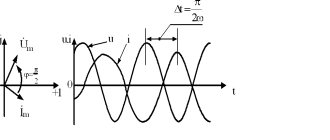
An interesting picture is obtained when connecting a capacitor to a source of alternating electrical voltage. Since the polarity and instantaneous voltage value of an alternating voltage source constantly changes (in a home electrical network according to a law close to sinusoidal). The capacitor will continuously charge and discharge, and alternating current will continuously flow through it. But this current will not be in phase with the voltage of the alternating voltage source, but will advance it by 90°, i.e. for a quarter period.
This will lead to the fact that the capacitor consumes energy from the network for half the period of alternating voltage, and releases half of the period, while the total active electrical power consumed is zero. But, since a significant current flows through the capacitor, which can be measured with an ammeter, it is customary to say that the capacitor is a consumer of reactive electrical power.
Reactive power is calculated as the product of current and voltage, but the unit of measurement is no longer watt, but volt-ampere reactive (VAr). Thus, a current of about 0.3 A flows through an electrical capacitor with a capacity of 4 μF connected to a 220 V network with a frequency of 50 Hz. This means that the capacitor consumes 0.3 x 220 = 66 (VAr) reactive power - comparable to the power of an average incandescent lamp, but the capacitor, unlike a lamp, does not glow or heat up.
Reactive inductive power
If the current in a capacitor leads the voltage, are there consumers where the current lags the voltage? Yes, and such consumers, unlike capacitive consumers, are called inductive, while remaining consumers of reactive energy. A typical inductive electrical load is a coil with a certain number of turns of highly conductive wire wound around a closed core of special magnetic material.
Active load
Devices with active loads include heating devices (irons, electric stoves, incandescent lamps, electric kettles). Such devices produce heat and light. They do not contain inductance or capacitance. A resistive load converts electrical energy into light and heat.
A reactive load contains capacitance and inductance. These parameters have the quality of collecting energy and then sending it to the network. An example would be an electric motor, an electric meat grinder, a household tool (vacuum cleaner, food processor). That is, all devices that contain electric motors.
What is reactive power?
First, let's look at the concept of electrical power. In the broadest sense of the word, this term means work performed per unit of time. In relation to electrical energy, we will slightly correct the concept of power: by electrical power we will understand a physical quantity that actually characterizes the rate of current generation or the amount of transmitted or consumed electricity per unit of time.
It is clear that the work of electricity per unit time is determined by electrical power, measured in watts. The instantaneous power in a section of the circuit is found by the formula: P = U×I , where U and I are the instantaneous values of the voltage and current parameters in this section.
Strictly speaking, the above formula is valid only for direct current. However, in sinusoidal current circuits, the formula only works when the consumer load is purely active. With a resistive load, all electrical energy is spent doing useful work. Examples of resistive loads are resistive devices such as a boiler or an incandescent lamp.
If there are capacitive or inductive loads in the electrical circuit, parasitic currents appear that are not involved in performing useful work. The power of these currents is called reactive.
With inductive and capacitive loads, some of the electricity is dissipated as heat, and some prevents useful work from being done.
Devices with inductive loads include:
- electric motors;
- chokes;
- transformers;
- electromagnetic relays and other devices containing windings.
Capacitors have capacitance.
Capacity Triangle
To understand the reactive load, consider the power triangle.
where P is active power, which is measured in Watts and is used to perform useful work;
Q – reactive, which is measured in Vars and is used to create an electromagnetic field;
S – total power is used to calculate electrical circuits.
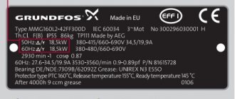
To calculate the total power, we use the Pythagorean theorem: S 2 =P 2 +Q 2. Or using the formula: S=U*I, where U is the voltage reading across the load, I is the reading of the ammeter, which is connected in series with the load. The calculations also use the power factor - cosφ. On devices that relate to reactive loads, active power and cosφ are usually indicated. Using these parameters you can also get full power.
Sometimes devices indicate total power, but cosφ is not indicated. In this case, a coefficient of 0.7 is applied.
Active and reactive electricity
When calculating the electrical power consumed by any electrical or household device, the so-called total power of the electric current performing a certain job in the circuit of a given load is usually taken into account. The term “apparent power” means all the power that is consumed by an electrical appliance and includes both an active component and a reactive component, which in turn is determined by the type of load used in the circuit. Active power is always measured and reported in watts (W), while apparent power is usually reported in volt-amperes (VA). Various devices that consume electrical energy can operate in circuits that have both active and reactive components of electric current.
The active component of the electric current power consumed by any load does useful work and is transformed into the types of energy we need (thermal, light, sound, etc.). Some electrical appliances operate mainly on this component of power. These are incandescent lamps, electric stoves, heaters, electric ovens, irons, etc. With the active power consumption value of 1 kW indicated in the device passport, it will consume a total power of 1 kVA from the network.
The reactive component of the electric current occurs only in circuits containing reactive elements (inductance and capacitance) and is usually spent on useless heating of the conductors that make up this circuit. Examples of such reactive loads are electric motors of various types, portable power tools (electric drills, angle grinders, wall chasers, etc.), as well as various household electronic equipment. The total power of these devices, measured in volt-amperes, and active power (in watts) are related to each other through the power factor cosφ, which can take a value from 0.5 to 0.9. These devices usually indicate the active power in watts and the value of the cosφ coefficient. To determine the total power consumption in VA, it is necessary to divide the active power value (W) by the cosφ coefficient.
Example: if an electric drill indicates a power value of 600 W and cosφ = 0.6, then it follows that the total power consumed by the tool is 600/0.6 = 1000 VA. In the absence of data on cosφ, you can take its approximate value, which for a household power tool is approximately 0.7.
When considering the issue of active and reactive components of electricity (more precisely, its power), we usually mean those phenomena that occur in alternating current circuits. It turned out that different loads in AC circuits behave completely differently. Some loads use the energy transferred to them for its intended purpose (i.e., to perform useful work), while another type of load first stores this energy and then gives it back to the power source.
Based on their behavior in AC circuits, various consumer loads are divided into the following two types:
1. The active type of load absorbs all the energy received from the source and converts it into useful work (light from a lamp, for example), and the shape of the current in the load exactly repeats the shape of the voltage across it (there is no phase shift).
2. The reactive type of load is characterized by the fact that first (over a certain period of time), it accumulates the energy supplied by the power source. Then the stored energy (over a certain period of time) is given back to this source. Such loads include electrical circuit elements such as capacitors and inductors, as well as devices containing them. Moreover, in such a load there is a phase shift of 90 degrees between voltage and current. Since the main purpose of existing power supply systems is to usefully deliver electricity from the producer directly to the consumer (rather than pumping it back and forth) - the reactive component of power is usually considered a harmful characteristic of the circuit.
Losses due to the reactive component in the network are directly related to the value of the power factor discussed above, i.e. The higher the cosφ of the consumer, the lower the power losses in the line will be and the cheaper it will be to transfer electricity to the consumer. Thus, it is the power factor that tells us how efficiently the operating power of the electricity source is used. In order to increase the power factor (cosφ), special methods of reactive power compensation are used in all types of electrical installations. Usually, to increase the power factor (by reducing the phase shift between current and voltage - angle φ), special compensating devices are included in the operating network, which are auxiliary generators of leading (capacitive) current. In addition, very often, to compensate for losses arising from the inductive component of the circuit, it uses banks of capacitors connected in parallel with the work load and used as synchronous compensators.
Nonlinear load
It has the peculiarity that voltage and current are not proportional. Nonlinear loads include televisions, stereos, electronic desktop clocks, computers and its components. The nonlinearity itself is due to the fact that this electronic device uses switching power supplies. To recharge the capacitors in the switching power supply, the top of a sine wave is sufficient.
The rest of the time, the capacitor does not consume energy from the network. In this case, the current has a pulse quality. What does this all lead to? This causes the sine wave to become distorted. But not all electronic devices work with a distorted sine wave. This problem is solved through the use of double conversion stabilizers, where mains power is converted to constant power. Then it is converted from a constant into a variable of the desired shape and amplitude.
2.4. Loads in AC circuits
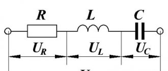
Active resistance (r) is a load similar to that used in DC circuits.
Reactances (X) are loads that were not used in DC circuits. They are used only in AC circuits and do not consume active power.
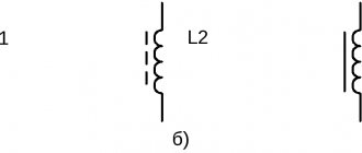
Inductance
Inductance (the first definition) is the property of a physical object (coil) to store the energy of a magnetic field and release it under the following conditions: if the current and voltage of the coil are of the same sign, energy is stored, but if they are of different signs, then energy is released by the coil.
Inductance (the second definition) is the coefficient of proportionality between flux linkage and the current that caused this flux linkage.
Inductance in diagrams is designated by the letter L and is measured in henry (H).
Let a coil be given (Fig. 2.5). If the integration circuit (k) is directed along the power line so that it covers all turns of the coil, then the law of the total current at H = const can be written: H k = wi
Magnetic induction is related to tension: B = m m0Н, where m is a relative value showing how many times the permeability of a given medium is greater than the magnetic permeability of vacuum; m0 is the magnetic permeability of vacuum.
Flux linkage (y) is determined by the flow: , where .
If H = const, then inductance, as a coefficient of proportionality between flux linkage and current, is equal to:
Then it becomes obvious that L is a parameter that depends on the number of turns, the geometric dimensions of the coil and the magnetic permeability of the medium.
Electrical capacity
This element, just like inductance, does not consume active power; its instantaneous power only fluctuates: it is either stored or released.
Similar to inductance, capacitance also has two definitions:
1) electric capacitance is the property of a physical object (in this case a capacitor) to store the energy of an electric field and transfer it to an external circuit at certain ratios of voltage and current. If the instantaneous voltage (u) and instantaneous current (i) of the capacitor are of the same sign, energy is stored by it, if u and i are of different signs, energy is released;
2) electric capacitance is the coefficient of proportionality between the charge (q) and the voltage (u) on the capacitor plates that caused this charge.
This definition follows from the formula: q = Cu.
Current (i) through a capacitor occurs when the charge on its plates changes in time: , and is similar to the appearance of voltage across the inductance:.
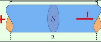
Let's write down the basic quantities and formulas for determining the capacitance of the capacitor (Fig. 2.6):
the dielectric constant:
;
Gauss's theorem:
;
formula for the relationship between electric displacement and electric field strength:
.
If the magnetic field strength is constant throughout the entire volume of the capacitor, then . The voltage on the plates, taking into account the stated conditions, is equal to:
,
then , and the capacitance of the capacitor:
In the terminals under consideration: D – electrical displacement; H - electric field strength; e is the dielectric constant of the medium; S – area of the capacitor plates; d – distance between plates.
Thus, the capacity of a linear capacitor does not depend on the charge or voltage, but is determined by the geometric dimensions and the medium between its plates.
Starting current
When calculating, it is necessary to take into account the starting currents of the device. For example, the resistance of the filament in a light bulb at the moment of switching on is 10 times less than in operating mode. Therefore, the starting current of this light bulb is 10 times greater. After some time, it will begin to consume the power that is recorded in the data of this light bulb. Therefore, when turned on, it burns out due to high inrush currents.
In electronic equipment, until the capacitor in the power supply is charged, an inrush current is also generated.
In electric motors, a starting current is also generated until the engine reaches rated speed.
In heating devices, a starting current is generated until the coil heats up to the standby temperature.
The meaning of reactive load
In an electrical circuit with a reactive load, the current phase and the voltage phase do not coincide in time. Depending on the nature of the connected equipment, the voltage either leads the current (in inductance) or lags behind it (in capacitance). Vector diagrams are used to describe issues. Here, the same direction of the voltage and current vector indicates the coincidence of phases. And if the vectors are depicted at a certain angle, then this is the advance or lag of the phase of the corresponding vector (voltage or current). Let's look at each of them.
In inductance, voltage always leads current. The “distance” between phases is measured in degrees, which is clearly illustrated in vector diagrams. The angle between the vectors is denoted by the Greek letter "Phi".
In an idealized inductance, the phase angle is 90 degrees. But in reality this is determined by the full load in the circuit, and in reality it cannot do without a resistive (active) component and a parasitic (in this case) capacitive component.
In a capacitor, the situation is the opposite - the current leads the voltage, because the inductance, when charging, consumes a large current, which decreases as it charges. Although it is more often said that voltage lags behind current.
To put it briefly and clearly, these shifts can be explained by the laws of commutation, according to which the voltage in a capacitor cannot change instantly, and the current in inductance cannot change.
Active-capacitive load
⇐ PreviousPage 3 of 5Next ⇒
Figure 11 – Circuit with active-capacitive load
Let's consider the influence of active-capacitive load using the example of the operation of a single-phase bridge rectifier.
Figure 12 – Dependence of currents and voltages
The figure shows graphical dependences of currents and voltages, explaining transient processes in the circuit at the moment the rectifier is connected to source U1.
In the interval tzap U1>UC and at the same time the capacitance C of the smoothing filter is charged through the internal resistance of the rectifier section. In this case, a large pulse current appears, the values of which are 20...40 times higher than the steady-state value of the average rectified valve current. This is especially pronounced in power supplies with a transformerless input. To limit this current, resistors, thermistors or resistors shunted by controlled switches, made on triacs, thyristors or dinistors, are introduced. The switches allow, taking into account the establishment time of the transient process, to limit the current only at the moment of starting the power source, therefore, the efficiency and reliability of the rectifier are increased.
In the interval ttimes, when the voltage on the capacitor is equalized with the source voltage, the capacitor is discharged to the load. As the load current increases, the level of rectified voltage ripple increases due to a decrease in the discharge circuit constant traz =RHC. In this case, the smoothing effects of the filter deteriorate.
When calculating a rectifier with a capacitive load, the Terentyev method is used - the nomogram method. It is based on the calculation of auxiliary coefficients depending on the angle of current flow through the valve. Enter the coefficient A=f(q), where q is the angle of current flow through the valve. For various rectifier circuits, nomograms are given that were obtained experimentally for various powers and rectifier circuits. Calculation of parameters Uobr, Iacr, Iad, U2, I2 is performed through auxiliary coefficients: B, C, D=f(A). To obtain the connection between the average current through the valve and parameter A, we perform integration over the interval q. When deriving the relationship, we assume the capacitance of the capacitor is close to infinity (СÞ¥), and the threshold voltage of the diode is equal to zero. To obtain the average value of the current through the valve, we move the coordinate axes to the middle of the current pulse and use the equation for the average current value: (1)
, (2).
The diagrams below explain the derivation of the relations for Ud.
Figure 13 – Relationship diagrams for Ud
At interval 2q, the valve current coincides with the load current. Let's equate (1) and (2) and divide the inner bracket in expression (1) by cosq, we get: .
Voltage doubling circuit
The classic (symmetrical) doubling circuit consists of two single-ended rectifiers, each of which uses its own half-wave voltage.
Figure 14 – Voltage doubling circuit
Figure 15 – Voltage graph
The voltage across the load is the sum of the voltages on capacitors C1 and C2. If the ripples are small, then the constant component on each capacitor is U01 ≈ U2m, and the voltage across the load is U0 ≈ 2U2m. In addition, when adding, the first and all odd ripple harmonics are compensated. Therefore, the circuit behaves like a push-pull circuit, although it consists of two single-cycle circuits. The disadvantage of the symmetrical doubling circuit, from a safety point of view, is the absence of a common point of load and transformer.
An asymmetrical doubling circuit is also used; its difference from the previous one is that the load has a common point with the transformer. Therefore, they can be connected to the housing, while the main ripple frequency is equal to the network frequency.
Figure 16 – Asymmetrical voltage doubling circuit
Figure 17 – Voltage graph of an asymmetrical circuit
In this asymmetrical circuit, capacitor C1 acts as an intermediate storage device and does not participate in smoothing pulsations, therefore its weight and size indicators are worse than those of a symmetrical doubler. However, there are also advantages. The diagram can be depicted like this:
Figure 18 - Alternative single-ended circuit
The result is a regular structure that can be expanded to form a voltage multiplier.
Figure 19 – Voltage multiplier
The load can be connected to any group of capacitors and get an even or odd multiplication. The diagram shows even multiplication - load voltage U0 ≈ 6Um2. Typically, such multipliers are assembled as a single block and filled with compound. The number of capacitors in the circuit is equal to the multiplication factor.
The calculated relationships for the considered schemes can be found in the reference book. The disadvantage of multiplication circuits is their high internal resistance and low efficiency due to the large number of recharges.
Transformerless high-voltage rectifiers with simultaneous charging of n pieces of storage capacitors C1 have higher efficiency.
Figure 20 – Transformerless high-voltage rectifier
Controlled charging and discharging switches Kz and Kr operate synchronously and in antiphase. capacitors C1 are charged in parallel from the network and sequentially discharged to the load through discharge switches Kr. In this case, the voltage at the load is n times greater than the amplitude of the network voltage.
Lecture 4. Controlled rectifiers.
Rectifier operating modes
Depending on the type of rectified current, there are three modes. Let us denote the conduction angle of the valves as λ.
The operating mode in which the valve currents follow each other without pauses, but the rectified current drops to zero, is called boundary (Fig. 5.1 a). In the boundary mode, the conduction angle of the valves is mπ = λ 2 deg. (5.1)
The operating mode in which the valve currents follow each other with a pause is called intermittent (Fig. 5.1 b). In intermittent mode, the conduction angle of the valves mπ < λ 2 ex. (5.2)
The operating mode in which the rectified current does not drop to zero, and the anode currents of neighboring valves overlap or follow without pauses, is called continuous (Fig. 5.1 c). In continuous mode, the conduction angle of the valves mπ ≥ λ 2 n. (5.3)
The operating mode significantly affects all characteristics of the rectifier.
⇐ Previous3Next ⇒
Recommended pages:
Use the site search:
Power triangle and cosine Phi
If you take the entire circuit, analyze its composition, phases of currents and voltages, then construct a vector diagram. After this, draw the active one along the horizontal axis, and the reactive one along the vertical axis and connect the ends of these vectors with the resulting vector - you get a triangle of powers.
It expresses the ratio of active and reactive power, and the vector connecting the ends of the two previous vectors will express the total power. This all sounds too dry and confusing, so look at the picture below:
The letter P denotes active power, Q – reactive power, S – apparent power.
The total power formula is:
The most attentive readers probably noticed the similarity of the formula to the Pythagorean theorem.
- P – W, kW (Watts);
- Q – VAR, kVAr (reactive volt-amperes);
- S – VA (Volt-Amps);
Calculations
To calculate the total power, use the formula in complex form. For example, for a generator the calculation looks like:
And for the consumer:
But let’s put this knowledge into practice and figure out how to calculate power consumption. As you know, we, ordinary consumers, pay only for the consumption of the active component of electricity:
P=S*cosФ
Here we see a new value of cosФ. This is the power factor, where Ф is the angle between the active and full components of the triangle. Then:
cosФ=P/S
In turn, reactive power is calculated using the formula:
Q = U*I*sinФ
To reinforce the information, watch the video lecture:
All of the above is also true for a three-phase circuit; only the formulas will differ.
