The simplest option is Relay
An electromagnetic relay is the simplest option for controlling a 220V load with a microcontroller. In essence, it is an ordinary electromagnet. When direct current is applied to the coil, a magnetic field is generated, the core is retracted and shorts the terminals. To control the relay itself, the same methods described in the article “How to control a DC motor” apply. It is important to pay attention to the relay holding current and the maximum current and switching voltage. Typically, the holding current is quite high, around 100 mA, and the voltage is 5 or 12V. Therefore, it will not be possible to control directly from the microcontroller. You will need a transistor.
Approximate relay connection diagram using a MOSFET transistor. As can be seen in the diagram, the presence of a diode is required. Additionally, you can limit the current consumption of the relay itself by connecting it in series through a resistor. Typically, the holding current is much less than the starting current when the relay is turned on. You can also add a capacitor to provide starting current. The complete diagram might look something like this:
The main disadvantage of a relay circuit is the presence of a mechanical part in the relay. It is this part that limits the switching frequency of the relay and allows the use of relays with a frequency of 0.5 Hz or less. Thus, the load relay can only be controlled in an on-off mode, without the ability to regulate the power supplied to the load.
Composite transistors. Switching schemes.
Transistors, as power elements of many radio-electronic devices, must perform the following functions for normal operation:
1. Provide control of a given load current with high power gain.
2. Have sufficient (taking into account the given output power and ranges of input and output voltages) power dissipation.
To assemble a radio-electronic device, you can pre-make a DIY KIT kit using the link.
3. Have the maximum permissible collector-emitter voltage, which allows, without the risk of breakdown, to ensure the required voltage drop at the collector-emitter junction at possible values of the input and output voltages.
In some cases, the available transistors do not allow one or more of the conditions described above to be met, then they resort to the help of so-called composite transistors. There are a great many circuits of composite transistors, but there are only three basic circuits.
We control the 220V load with power regulation
I would like to be able to regulate the power supplied to the controlled device in the range from 0 to 100%. This is the problem we will solve.
As you know, the household electrical network has an alternating voltage of 220V with a frequency of 50 Hz. On the oscillogram it looks like this:
The voltage changes in a sine wave, changing polarity every 10 ms. There are two methods to limit the total power of a sine wave:
- phase method
- full half cycle method
In the phase method, the load is disconnected from the network for part of the time of each half-cycle; the disconnection is usually made after passing through 0. The voltage supplied to the load in this case looks like this:
In the second method, full cycles or half cycles, the load is switched off for a whole number of periods:
For example, it might look like this in the case of half-cycles. With this type of control, it is important to ensure that the average current is zero.
Let's take a closer look at how to manage the load using the full periods method. It provides less interference to the 220V network, since the current and voltage in the load increase synchronously and produce less emissions into the network.
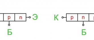
Tandem connection of transistors (Darlington and Sziklai circuits)
Quite often a situation arises when the required gain of one transistor is not enough. In this case, the transistors are connected in tandem (that is, the output current of the first transistor is the input current for the second). There are two schemes for such inclusion: the Darlington scheme and the Szyklai scheme. The only difference is that the Darlington circuit uses transistors of the same conductivity type, and the Szyklai circuit uses different conductivity types.
Darlington Scheme Siklai Scheme
These pairs are simply two emitter follower stages. These stacked transistor circuits are sometimes called "super-β" pairs because they function as a single high-gain transistor.
The overall current transfer coefficient will be equal to:
When using these circuits, a situation is quite possible when the load decreases to zero (or some minimum value close to zero) or when the temperature rises, the base current of transistor VT1 can become zero or even change direction due to the uncontrolled reverse collector current. To avoid blocking transistor VT2, its mode should be stabilized using resistor R1.
The value of resistance R1 can be determined by the formula:
Triac - a powerful key for a 220 V network
The easiest way to control a 220V load is to use a relay. It allows you to control a powerful load using constant voltage. This article will not discuss this method; it is quite simple. It is enough to apply voltage to the relay magnet and it will close the contacts. Unfortunately, the relay does not control the load quickly enough. With a large number of on/off switches, it quickly breaks down. Also, at the moment of switching, large impulse noise occurs. It is better to use a relay with a control frequency of no more than once every 2-3 seconds.
As we already know from the article “How to control a DC motor,” in DC circuits, a transistor is an electronic switch, a device that allows a low voltage or current to control a more powerful load.
For alternating current, there are also such electronic keys - misto.
The triac conducts current in both directions, therefore it is used in alternating current networks. To control the load, the main electrodes of the triac are connected in series with the load. In the closed state, there is no conductivity of the triac, the load is turned off. When an unlocking signal is applied to the control electrode, conduction occurs between the main electrodes of the triac, and the load turns on.
To keep the triac open, there is no need to constantly apply a signal to the control electrode (unlike a transistor). It remains open as long as the current flowing through the main terminals exceeds a certain value called the holding current. It follows that switching off the load in the AC circuit occurs near the moments in time when the current through the main electrodes of the triac changes direction (usually this coincides in time with a change in the polarity of the voltage in the AC network). This point on the sine wave is called the zero crossing.
The triac can be controlled directly from the microcontroller, but this requires a fairly large current - 10-20 mA. There are also logical triacs. Their control current is about 5 mA. It is better to use ordinary triacs in circuits; they are more protected from spontaneous opening. What is it and how can you control ordinary triacs? Read on.
First, let's see how powerful a load a typical triac can control. Let's take the BT139-800 triac as an example .
The datasheet usually contains graphs of the power released by the triac when controlling the load. Here is an example of such a graph.
Knowing the released power, we use the parameters of heat dissipation by the case to obtain the heating temperature of the triac and evaluate its performance.
From all these parameters it follows that without a radiator, this triac can dissipate about 2W of heat. When controlling full half-cycles, you need to take the current graph for a=180 degrees. The graph in this area is almost linear, so we can say that the average current will be about 2A.
That is, without a radiator, this triac will be able to control a load of 2A * 220V = 440 W. In other cases, a radiator will be needed.
Now let's figure out how a microcontroller can control a powerful triac?
Main types of connections:
- Parallel - used when it is necessary to increase the maximum current;
- Mixed - parallel + serial.
Serial - used when it is necessary to increase the maximum blocking voltage;
When connecting thyristors or diodes in parallel, it is necessary to strive for equal distribution of the load current across the devices. It is necessary to ensure the identical operating conditions of the SPP and the equality of current-voltage characteristics, taking into account the technological variation in parameters.
Optosimistor is a convenient method of controlling a powerful triac microcontroller
Since the triac conducts current in both directions, then in relation to its main terminals, the control current can be located in four squares.
You can also present this in table form:
The datasheet shows in which quadrants a particular triac is controlled and what current is needed for this. For example, the selected triac is controlled in all 4 quadrants. But at the same time, the control current and protective properties against false alarms differ.
It can be seen that the 4th quadrant is the most disadvantageous. The control current increases sharply. Also, the protective properties with such control decrease.
This leads to the conclusion that when controlling a microcontroller, it is better to control in quadrants 1-3.
If the control is direct, then the MK must be able to change the polarity of the output, which is difficult, or have a positive power supply in common with terminal A1 (control will be in the second and third quadrants). The second option is not difficult to implement with a capacitor power supply. This appnote AN2986 discusses this case in detail.
The second option is to control via an optosimistor. There are quite a lot of such devices and they are inexpensive. For example - MOC3041. There are optosimistors with a built-in zero-crossing control circuit; they can only turn off near zero. This is what we need for the full period control scheme. And there is one without this scheme. With their help you can control the phase method.
The control circuit using an optosimistor is as follows:
The device itself looks like this inside:
In this case, control is of the same polarity as terminal A2, that is, in the first and third quadrants.
Additionally, the optosimistor isolates the microcontroller operating circuit from the network, which reduces interference and increases the reliability of the device. If there are no requirements for the compactness of the device, then we recommend using optosimistors to control other more powerful triacs.
Triac protection circuit against network interference
If the voltage at the main terminals of the triac or the current changes too quickly, it may spontaneously open and begin to conduct current. This is very unpleasant. This can mainly happen when driving an inductive load (the inductance resists a change in current). But this can also happen when a device with inductance is operating nearby in the network (for example, when a motor and a soldering gun controlled by a microcontroller operate through the same socket). In this case, regardless of the microcontroller, the controlled load will not be disconnected from the network and the current will continue to flow. For example, when operating a soldering gun, this situation can even lead to a fire.
A simple defense against this case is a snubber circuit (resistor plus capacitor):
But it does not guarantee work in all cases. The parameters are calculated for a specific inductance. Appnote AN-3004 discusses snubber calculations in detail.
The second option is to use triacs operating in quadrants 1-3. For example, T405. The manufacturer indicates that they can be used to control even inductive loads without a snubber.
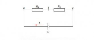
Serial connection of transistors
During operation of the power transistor, a voltage drops at its collector-emitter junction, which is the difference between the input and output voltages. In some cases, this difference may exceed the maximum permissible collector-emitter voltage of the transistor available. In this case, it is necessary to use a series connection of several transistors.
Circuit for sequential connection of transistors
An equivalent transistor would have the following parameters:
To balance the voltages that will drop at the collector-emitter transition of transistors, balancing resistors R1 and R2 resistance are introduced, which can be determined by the formula
where IB is the base current of the composite regulating transistor.
Theory is good, but without practical application it’s just words. Here you can do everything with your own hands.
Phase method
To solve the problem of phase control of the load, the microcontroller needs to know when the zero crossing was made. Then it will be possible to calculate the delay time for turning on the load.
The simplest method for obtaining an AC zero-crossing event is described in detail in appnote AN521 from Microchip. Almost every microcontroller has high-voltage protection diodes on each digital input. This can be used to obtain zero crossing information. It is enough to install a high-resistance resistor at the input, limiting the current at the MK output to the values specified in the datasheet on the MK. In this case, the output in normal digital mode will take the value 0 at the moment of zero crossing. The time delay from real state to real state will be minimal and is about 50 μs.
The disadvantage of this scheme is the lack of galvanic isolation of the control circuit from the 220V network. If necessary, an optocoupler can be used.
Well, then, you can already control a powerful triac as described earlier, only if you do this through an optosimistor, then without a zero-crossing circuit.
This article examines the basic methods of controlling a powerful load of a 220V AC network using triacs. After reading the theoretical part, let's move on to practice. A soldering station is a device in which a microcontroller controls a powerful soldering gun operating from a 220V network.
Reasons for uneven distribution of blocking stresses:
- Differences in leakage in series-connected devices due to natural technological variation and (or) different operating temperatures due, for example, to different cooling conditions (note: on average, a temperature change of 8°C leads to a twofold change in leakage). Overvoltage occurs on devices that have a lower leakage current;
- The dispersion of the turn-on time of individual thyristors connected in series in branches leads to a redistribution of voltage between the thyristors that turned on earlier and those that turned on late. Overvoltage occurs on thyristors that turn on late;
- The spread of reverse recovery charge values in series-connected devices leads to the fact that at the moment of recovery such devices receive reverse voltage at different times. Overvoltage occurs on thyristors that have a lower reverse recovery charge.