What are electrical circuits
An electrical circuit is a set of devices necessary for the passage of electric current through them.
An electrical circuit is a complex of various elements connected to each other. It is designed to allow electrical current to flow where transients occur. The movement of electrons is driven by potential differences and can be described using terms such as voltage and current.
The internal circuit is provided by connecting voltage as a power source. The remaining elements form the external network. For the movement of charges in the field power source, the application of an external force will be required. This can be a winding of a generator, transformer or galvanic source.
For such a system to function correctly, its circuit must be closed, otherwise no current will flow. This is a prerequisite for coordinated operation of all devices. Not every circuit can be an electrical circuit. For example, grounding or protection lines are not grounding or protection lines because no current flows through them in normal operation. They can be called electric based on their operating principle. In an emergency, current passes through them, and the circuit closes, going into the ground.
Depending on the power source, the voltage in the circuit can be constant or variable. The battery of elements provides constant voltage, and the windings of generators or transformers provide alternating voltage.
Example of a real circuit
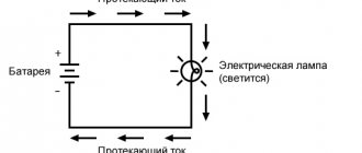
You can make the simplest electrical circuit yourself. It is often collected in physics class. In this case, you should not be afraid of electric shock, since it will use a low-voltage voltage source. But still, before you start assembling, you should be aware of the short circuit. It refers to a condition in which the output is short-circuited.
In other words, all the energy of the current source is applied to it. As a result, the potential difference is reduced to zero, and maximum current strength appears in the circuit. An unintentional short circuit can damage the generator and radio components. It is to protect against this harmful effect that a fuse is installed in the circuit.
The circuit for independent repetition will be a lighting control unit. To assemble it you need to prepare:
- 12 volt power supply. This could be a battery, an adjustable laboratory unit, or batteries. The main thing is that the source can produce the required voltage. For example, the desired value can be obtained by connecting several batteries in series with a standard rating of 1.5 V (1.5 * 4 = 12 V).
- Bulb. Suitable for incandescent. Here it is important to pay attention to its characteristics. It must be designed for the required voltage.
- Key. This is an ordinary switch that has two stable states - open and closed.
- Wires. In the assembly, you can use any copper conductors with a cross section of 0.25 mm2.
The structure is assembled as follows. A wire is connected to the positive side of the battery and the other end is connected to the switch. Then the free end of the key is soldered to any of the lamp terminals. The other electrode of the lighting device is connected to the minus of the source. The scheme is ready. If you now turn the key to the “on” position, a light will appear.
Main components
Electric Current Inverter
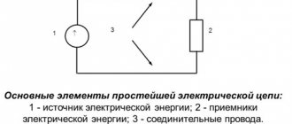
All components in a circuit participate in the same electromagnetic process. They are conventionally divided into three groups.
- Primary sources of electrical energy and signals can convert energy of a non-electromagnetic nature into electrical energy. For example, a galvanic cell, a battery, an electromechanical generator.
- The secondary type has electrical energy at both the input and output. Only its parameters change - voltage and current, their shape, magnitude and frequency. Examples could be rectifiers, inverters, transformers.
- Active energy consumers convert electric current into lighting or heat. These are electrothermal devices, lamps, resistors, electric motors.
- Accessory components include switching devices, measuring instruments, connecting elements and wire.
The basis of an electrical network is a circuit.
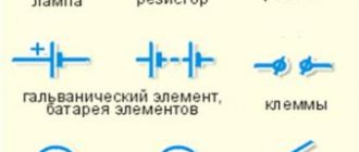
This is a graphic drawing that contains conventional images and symbols of elements and their connection. They are carried out in accordance with GOST 2.721-74 - 2.758-81 The circuit of the simplest line includes a galvanic element. An incandescent lamp is connected to it via a switch using wires. It includes a voltmeter and an ammeter to measure current and voltage.
Circuit classification
Electrical circuits are classified by type of complexity: simple (unbranched) and complex (branched). There is a division into DC and AC circuits, as well as sinusoidal and non-sinusoidal. Based on the nature of the elements, they are linear and nonlinear. AC lines can be single-phase or three-phase.
Branched and unbranched
The same current flows in all elements of an unbranched circuit. The simplest branched line includes three branches and two nodes. Each branch has its own current flowing. A branch is defined as a section of a chain that is formed by sequentially connected elements located between two nodes. A node is a point where three branches meet.
If a dot is placed on the diagram at the intersection of two straight lines, there is an electrical connection of two lines at this place. If the node is not marked, the chain is unbranched.
Linear and nonlinear
An electrical circuit in which consumers do not depend on the voltage and direction of currents, and all components are linear, is called linear. The elements of such a circuit include dependent and independent sources of currents and voltages. In a linear element, the resistance of the element does not depend on the current, for example, an electric furnace.
In nonlinear, passive elements depend on the values of the direction of currents and voltage, and have at least one nonlinear element. For example, the resistance of an incandescent lamp depends on voltage and current surges.
Designations of elements on the diagram
Before proceeding with the installation of equipment, it is necessary to study the regulatory accompanying documents.
The diagram allows you to convey to the user the full characteristics of the product using letter and graphic symbols entered into a unified register of design documentation. Additional documents are attached to the drawing. Their list can be indicated in alphabetical order with digital sorting on the drawing itself, or on a separate sheet. Ten types of circuits are classified; in electrical engineering, three main circuits are usually used.
- Functional has minimal detail. The main functions of the nodes are represented by a rectangle with letter symbols.
- The schematic diagram shows in detail the design of the elements used, as well as their connections and contacts. The required parameters can be displayed directly on the diagram or in a separate document. If only part of the installation is indicated, it is a single-line diagram; when all elements are indicated, it is complete.
- The electrical wiring diagram uses positional designations of elements, their location, installation method and sequence.
To read electrical diagrams, you need to know the graphic symbols. The wires that connect the elements are represented by lines. The solid line is a general designation for wiring. Above it may be information about the installation method, material, voltage, current. For a single-line diagram, a group of conductors is depicted with a dotted line. At the beginning and at the end indicate the marking of the wire and the place of its connection.
Vertical notches on the wiring line indicate the number of conductors. If there are more than three, digital designation is performed. The broken line indicates control circuits, security, evacuation, and emergency lighting networks.
The switch in the diagram looks like a circle with a line tilted to the right. The device parameters are determined by the type and number of dashes.
In addition to the main drawings, there are substitution diagrams.
Graphic image
A real or virtual electrical circuit can be depicted in a figure. It is called a circuit diagram or electrical diagram. The difference between them is that on the first the main blocks and their connections are drawn, and on the second the location and connection are indicated.
Essentially, a diagram is a graphical representation of an electrical circuit. To designate certain elements, special symbols are used. Their design has its own standard, so anyone versed in electronics or electrical engineering can understand what this or that circuit is intended for.
In Russia, drawing of all types of electronic components is carried out in accordance with GOST 2.702−2011.
For example, the simplest designation for conductors is a straight line. They are used to show how elements are connected. They are the basis for any electrical circuit. In addition to the conductors and the elements themselves, there are always two more conditional parameters in the circuit:
- branch - a section through which the same current flows;
- node - a point at which more than two branches join.
Based on this terminology, we can say that the branches connected to one pair of points will be parallel, and the closed path passing through them will form a circuit. The simplest electrical circuit consists of a single-circuit circuit, while complex ones include several circuits.
Often in conventional graphic designation, the common wire, that is, the conductor through which the current returns to the generator, is designated with a special symbol. They call it "minus". Such a connection is drawn using two perpendicular lines connected to the terminal of the block. The direction of the current is not indicated on the diagrams, but a plus sign is placed next to some elements or another designation for the positive terminal is used.
Special mention should be made of substitution schemes. They are used for convenience, replacing the real device with equivalent passive radio elements. This approach is used when it is necessary to calculate the parameters of a complete electrical circuit or some part of it. Individual blocks in the diagrams are outlined with dotted lines. With their help, parts of the chain are combined according to their functional characteristics. For example, they separate the power part from the secondary part, the logical part from the converter part.
Three-phase electrical circuits
Three-phase circuit in operating mode
Both single-phase and multi-phase systems are common among electrical circuits. Each part of a polyphase circuit is characterized by the same current value and is called a phase. Electrical engineering distinguishes two concepts of this term. The first is a direct component of a three-phase system. The second is a quantity that changes sinusoidally.
A three-phase circuit is one of the multiphase alternating current systems where sinusoidal EMF (electromotive force) of the same frequency acts, which are shifted in time relative to each other by a certain phase angle. It is formed by the windings of a three-phase generator, three power receivers and connecting wires.
Such circuits serve to ensure the generation of electrical energy, for its transmission, distribution, and have the following advantages:
- cost-effectiveness of electricity generation and transportation compared to a single-phase system;
- simple generation of a magnetic field, which is necessary for the operation of a three-phase asynchronous electric motor;
- the same generator set produces two operating voltages - linear and phase.
The three-phase system is beneficial when transmitting electricity over long distances. In addition, material consumption is significantly lower than single-phase ones. The main consumers are transformers, asynchronous electric motors, converters, induction furnaces, powerful heating and power units. Among single-phase low-power devices we can mention power tools, incandescent lamps, household appliances, and power supplies.
The three-phase circuit is characterized by a significant balance of the system. The methods for connecting the phases received the “star” and “triangle” structures. Typically, the phases of generating electric machines are connected by a “star”, and the phases of consumers are connected by a “star” and a “triangle”.
Parallel connection of energy receivers
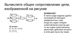
Another way to connect electrical energy receivers is a parallel connection, which is characterized by the fact that several energy successors are connected to the same nodes of the electrical circuit. An example of such a connection is shown in the figure below
An example of parallel connection of energy receivers.
The electrical circuit in the figure consists of three parallel branches with load resistances R1, R2 and R3. The circuit is connected to an energy source with a voltage U, an electric current with a force I flows through the circuit. Thus, a current flows through each branch equal to the ratio of the voltage to the resistance of each branch
Since all branches of the circuit are under the same voltage U, the currents of the energy receivers are inversely proportional to the resistances of these receivers, and therefore parallel connected energy receivers can be seen as one energy receiver with the corresponding equivalent resistance, according to the following expressions
Thus, with a parallel connection, the equivalent resistance is always less than the smallest of the parallel-connected resistances.
Laws applicable in electrical circuits
In the diagrams, the direction of currents is indicated by arrows. To calculate, you need to take the directions for voltages, currents, and EMF. When making calculations in electrical engineering, the following basic laws are used:
- Ohm's law for a straight section of a circuit, which determines the relationship between the electromotive force, the source voltage with the current flowing in the conductor and the resistance of the conductor itself.
- To find all currents and voltages, use Kirchhoff's rules, which operate between currents and voltages in any part of an electrical circuit.
- The Joule–Lenz law provides a quantitative estimate of the thermal effect of electric current.
In DC circuits, the direction of action of the electromotive force is indicated from negative to positive potential. The direction is taken to be the movement of positive charges. In this case, the arrow is directed from higher potential to smaller. Voltage is always directed in the same direction as the current.
In sinusoidal circuits, EMF, voltage and current are indicated using the half-cycle of the current, while it does not change its direction. To emphasize the difference in potentials, they are denoted by the signs “+” and “–”.