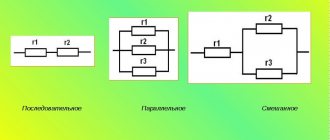
All known types of conductors have certain properties, including electrical resistance. This quality has found its application in resistors, which are circuit elements with a precisely set resistance. They allow you to adjust current and voltage with high precision in circuits. All such resistances have their own individual qualities. For example, the power for parallel and series connection of resistors will be different. Therefore, in practice, various calculation methods are often used, thanks to which it is possible to obtain accurate results.
Sample task
Two conductors with resistance $R_1 = 2 \space Ohm$ and $R_2 = 3 \space Ohm$ are connected in series. The current strength in the circuit is $1 \space A$. Determine the resistance of the circuit, the voltage on each conductor, and the total voltage of the entire circuit section.
Since the conductors are connected in series , we will use the formulas learned in this lesson.
Given: $R_1 = 2 \space Ohm$ $R_2 = 3 \space Ohm$ $I = 1 \space A$
$R — ?$ $U_1 — ?$ $U_2 — ?$ $U — ?$
Solution:
The total resistance of the circuit will be equal to the sum of the resistances of its constituent conductors: $R = R_1 + R_2$.
Let's calculate it: $R = 2 \space Ohm + 3 \space Ohm = 5 \space Ohm$.
The current strength in all sections of the circuit will be the same and equal to $1 \space A$.
Let's write Ohm's law for the section of the circuit with the first conductor and express from it the voltage at the ends of the first conductor: $I = \frac{U_1}{R_1}$, $U_1 = IR_1$.
Let's calculate it: $U_1 = 1 \space A \cdot 2 \space Ohm = 2 \space B$.
We also calculate the voltage at the ends of the second conductor: $I = \frac{U_2}{R_2}$, $U_2 = IR_2$, $U_2 = 1 \space A \cdot 3 \space Ohm = 3 \space B$.
When connecting conductors in series, we can calculate the total voltage in the circuit in two ways.
Method No. 1 The voltage on the entire circuit is equal to the sum of the voltages at the ends of the conductors in this circuit: $U = U_1 + U_2$, $U = 2 \space V + 3 \space V = 5 \space V$.
Method No. 2 We already know the total resistance of the two conductors. It turns out that we can imagine these two conductors as one whole. We use Ohm's law for the circuit section: $I = \frac{U}{R}$, $U = IR$, $U = 1 \space A \cdot 5 \space Ohm = 5 \space B$.
Answer: $R = 5 \space Ohm$, $U_1 = 2 \space V$, $U_2 = 3 \space V$, $U = 5 \space V$.
Mixed compound
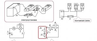
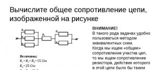
Circuits with a mixed connection of resistors contain a series and parallel connection. This circuit can be easily converted by replacing the parallel connection of resistors with a series one. To do this, first replace the resistances R2 and R6 with their common R2.6, using the formula given below:
R2.6=R2∙R6/R2+R6.
In the same way, two parallel resistors R4, R5 are replaced with one R4.5:
R4.5=R4∙R5/R4+R5.
The result is a new, simpler circuit. Both diagrams are shown below.
The power of resistors in a circuit with a mixed connection is determined by the formula:
P=U∙I.
To calculate using this formula, first find the voltage at each resistance and the amount of current through it. Another method can be used to determine the power of the resistors. The formula used for this is:
P=U∙I=(I∙R)∙I=I2∙R.
If only the voltage across the resistors is known, then another formula is used:
P=U∙I=U∙(U/R)=U2/R.
All three formulas are often used in practice.
Let's look at some calculations for connecting heating elements.
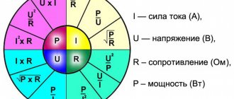
General formulas
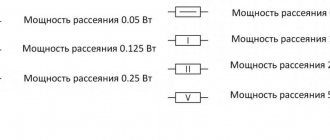
| Power (Watt) |
| Voltage (Volts) |
| Current (Ampere) |
| Resistance (Ohm) |
Let's consider the serial or parallel connection of several identical heating elements with different connection schemes. To carry out the calculations we need the following characteristics:
R = impedance P = total power U and I respectively voltage and current
Resistance in a circuit when conductors are connected in series
How to find the total resistance of a circuit, knowing the resistance of individual conductors, in a series connection?
Let's speculate. There was one conductor in the circuit with a certain resistance. We connect the second one in series. Let's imagine these two conductors as one circuit element. Then it turns out that by connecting the second conductor, we increased the length of the first.
Resistance depends on the length of the conductor. Therefore, the total resistance of the circuit will be exactly greater than the resistance of one conductor.
The total resistance of a circuit in a series connection is equal to the sum of the resistances of individual conductors (or individual sections of the circuit): $R = R_1 + R_2 + … + R_n$.
On electrical circuit diagrams, a series connection of several conductors is depicted as shown in Figure 4.
Figure 4. Series connection of conductors in an electrical circuit diagram
Resistors
Connecting in series
[Resistance of series connected resistors, kOhm
] = [
Resistance of the first resistor, kOhm
] + [
Resistance of the second resistor, kOhm
]
[Power dissipated by the first resistor, W
] = [
Resistance of the first resistor, kOhm
] * [
Current strength, mA
] ^ 2 / 1000
[Power dissipated by the second resistor, W
] = [
Resistance of the second resistor, kOhm
] * [
Current strength, mA
] ^ 2 / 1000
It turns out that from two 500 Ohm 2 W resistors you can make one 1 kOhm 4 W resistor.
Connect in parallel
[Resistance of parallel connected resistors, kOhm
] = 1 / (1 / [
Resistance of the first resistor, kOhm
] + 1 / [
Resistance of the second resistor, kOhm
])
This formula is intuitive and can be formally derived from the following considerations. At a given voltage across the resistors, each of them independently carries a current equal to the voltage divided by the resistance. The total resistance is equal to the voltage divided by the total current. In the formulas, the voltage value is happily reduced, and the given formula is obtained.
[Power dissipated by the first resistor, W
] = [
Voltage across resistors, V
] ^ 2 / [
Resistance of the first resistor, kOhm
] / 1000
[Power dissipated by the second resistor, W
] = [
Voltage across resistors, V
] ^ 2 / [
Resistance of the first resistor, kOhm
] / 1000
It turns out that from two 500 Ohm 2 W resistors you can make one 250 Ohm 4 W resistor.
Unfortunately, errors are periodically found in articles; they are corrected, articles are supplemented, developed, and new ones are prepared. Subscribe to the news to stay informed.
Practice of electronic circuit design. Electronics self-instruction manual. The art of device development. Element base of radio electronics. Typical schemes.
Application of thyristors (dinistors, thyristors, triacs). Scheme. Is. Thyristors in electronic circuits. Subtleties and features of use. Types of thyris.
Bipolar transistor. Principle of operation. Application. Types, species, category. All about the bipolar transistor. Principle of operation. Application in circuits. Properties. Cla.
Smooth adjustment of the brightness of fluorescent fluorescent lamps. Driver circuit for smoothly adjusting the brightness of fluorescent lamps. Dra.
Checking electronic elements and radio components. Check serviceability, p. How to check the serviceability of a part. Test method. What parts can be used?
RC - chain. Resistor-capacitor circuit. Resistor, capacitor. I. Calculation of RC circuits, voltage changes on the capacitor depending on time.
How to connect heaters correctly: in parallel or in series?
So, should heaters be connected in parallel or in series ?
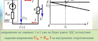
This question arises when more than one heater needs to be connected to the power supply. Any number of heaters can be connected in parallel, but usually only two heaters are connected in series. Reliably daisy chaining more than two heaters is challenging. If the heaters are connected in series, the failure of one heater stops the operation of all heating elements in the chain. When heaters are connected in parallel, the failure of one heating element usually does not affect the other heaters. Most often, two heating elements are used when connecting. In this case, if the heaters are connected in series, the voltage of each heating element should be equal to half the total available voltage. For example, two 240-volt heaters connected in series to a 480-volt power supply. Also, the power of each heater should be the same. (If the power and voltage of each heater are not equal, the heaters will not share the total voltage equally.) If two heaters are connected in parallel, the voltage of each heater must be the same as the supply voltage.
Power with parallel connection
With a parallel connection, all the beginnings of the resistors are connected to one node of the circuit, and the ends to another. In this case, the current branches out and it begins to flow through each element. According to Ohm's law, the current will be inversely proportional to all connected resistances, and the voltage value across all resistors will be the same.
Before calculating the current, it is necessary to calculate the admittance of all resistors using the following formula:
- 1/R = 1/R1+1/R2+1/R3+1/R4 = 1/200+1/100+1/51+1/39 = 0.005+0.01+0.0196+0.0256 = 0.06024 1/Ohm.
- Since resistance is a quantity inversely proportional to conductivity, its value will be: R = 1/0.06024 = 16.6 Ohms.
- Using a voltage value of 100 V, Ohm's law calculates the current: I = U/R = 100 x 0.06024 = 6.024 A.
- Knowing the current strength, the power of resistors connected in parallel is determined as follows: P = I 2 x R = 6.024 2 x 16.6 = 602.3 W.
- The current for each resistor is calculated using the formulas: I1 = U/R1 = 100/200 = 0.5A; I2 = U/R2 = 100/100 = 1A; I3 = U/R3 = 100/51 = 1.96A; I4 = U/R4 = 100/39 = 2.56A. Using these resistances as an example, a pattern can be seen that as the resistance decreases, the current increases.
There is another formula that allows you to calculate the power when resistors are connected in parallel: P1 = U 2 /R1 = 100 2 /200 = 50 W; P2 = U 2 /R2 = 100 2 /100 = 100 W; P3 = U 2 /R3 = 100 2 /51 = 195.9 W; P4 = U 2 /R4 = 100 2 /39 = 256.4 W. By adding up the powers of individual resistors, you get their total power: P = P1+P2+P3+P4 = 50+100+195.9+256.4 = 602.3 W.
Thus, the power for series and parallel connection of resistors is determined in different ways, with the help of which the most accurate results can be obtained.
When designing electrical circuits, it becomes necessary to use series and parallel connections of resistors.
The connections are also used when repairing electrical equipment, since in some situations it is impossible to find an equivalent resistor value. The calculation is simple, and anyone can handle this operation.
Current strength in the circuit when the conductors are connected in series
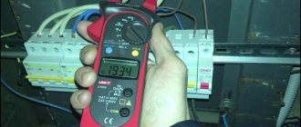
When studying the current strength, we measured it in various parts of the electrical circuit (Figure 3). The current values obtained using an ammeter were the same.
Figure 3. Measuring current in various parts of an electrical circuit when its elements are connected in series
Moreover, all our elements were connected in series. Let's draw a conclusion.
With a series connection, the current strength in any part of the circuit is the same: $I = I_1 = I_2 = ... = I_n$.
Voltage in the circuit when the conductors are connected in series
Using Ohm's law for a section of a circuit, we can find the voltage at the ends of these sections: $U_1 = IR_1$, $U_2 = IR_2$, ... $U_n = IR_n$.
It turns out that the voltage will be greater, the greater the resistance in the sections of the circuit. The current strength will be the same everywhere.
How to find the voltage of a section of a circuit consisting of conductors connected in series, knowing the voltage on each?
The total voltage in the circuit in a series connection, or the voltage at the poles of the current source, is equal to the sum of the voltages in individual sections of the circuit: $U = U_1 + U_2 + … + U_n$.