The concept of a network driver and its purpose
A driver is an electronic component that receives AC voltage, stabilizes it, and outputs DC voltage. It is important to understand here that we are talking about receiving current. To convert voltage, conventional power supplies are used (the value of the output voltage is indicated on the case). Power supplies are operated in diode strips.
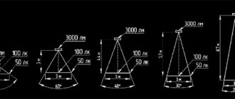
The main characteristic of the converter for LED lighting devices is the output current. Auxiliary LED diodes or other semiconductors are used for the load. Almost always, the driver is powered from a 220 V industrial network, and the output voltage range starts from 2 - 3 and ends in tens of volts. To connect three 3 W LEDs, you need an electronic driver with an output voltage of 9 - 21 V and a current of 780 mA. At light loads, the universal device is characterized by a low coefficient of performance (COP).
To power vehicle headlights, a source with a constant voltage of 10 to 35 V is used. If the power is low, a driver is not necessary, but an appropriate resistor will be required. This component is an indispensable part of a household switch, but when switching an LED diode to a 220 V AC network, you cannot count on reliable and durable operation.
LED driver. Why is it needed and how to choose it?
Recently, consumers are increasingly interested in LED lighting. The popularity of LED lamps is quite justified - the new lighting technology does not emit ultraviolet radiation, is economical, and the service life of such lamps is more than 10 years. In addition, with the help of LED elements in home and office interiors, it is easy to create original light textures outdoors.
If you decide to purchase such devices for your home or office, then you should know that they are very demanding on the parameters of electrical networks. For optimal lighting performance, you will need an LED driver. Since the construction market is overflowing with devices of varying quality and pricing, before purchasing LED devices and a power supply for them, it is a good idea to familiarize yourself with the basic advice given by experts in this matter.
First, let's look at why such a device as a driver is needed.
What is the purpose of the drivers?
A driver (power supply) is a device that performs the functions of stabilizing the current flowing through the LED circuit and is responsible for ensuring that the device you purchased works for the number of hours guaranteed by the manufacturer. When selecting a power supply, you must first thoroughly study its output characteristics, including current, voltage, power, efficiency, as well as the degree of its protection and exposure to external factors.
For example, the brightness of the LED depends on the current flow characteristics. The digital voltage symbol reflects the range in which the driver operates during possible voltage surges. And of course, the higher the efficiency, the more efficiently the device will work, and its service life will be longer.
Where are LED drivers used?
An electronic device - a driver - is usually powered from a 220V electrical network, but is designed to operate with very low voltages of 10, 12 and 24V. The operating output voltage range, in most cases, is from 3V to several tens of volts. For example, you need to connect seven 3V LEDs. In this case, you will need a driver with an output voltage from 9 to 24V, which is rated at 780 mA. Please note that, despite its versatility, such a driver will have a low efficiency if you give it a minimum load.
If you need to install lighting in a car, insert a lamp into a bicycle or motorcycle headlight, into one or two small street lamps or into a hand lamp, a power supply from 9 to 36V will be enough for you.
More powerful LED drivers will need to be selected if you intend to connect an LED system consisting of three or more devices outdoors, have chosen it to decorate your interior, or if you have office table lamps that operate at least 8 hours a day .
How does the driver work?
As we have already said, the LED driver acts as a current source. The voltage source produces a certain voltage at its output, ideally independent of the load.
For example, let's connect a 40 Ohm resistor to a 12 V source. A current of 300mA will flow through it.
Now let's turn on two resistors at once. The total current will be already 600mA.
The power supply maintains the specified current at its output. The voltage may change in this case. Let's also connect a 40 Ohm resistor to the 300 mA driver.
The power supply will create a 12V voltage drop across the resistor.
If you connect two resistors in parallel, the current will also be 300mA, and the voltage will drop by half.
What are the main characteristics of an LED driver?
When selecting a driver, be sure to pay attention to parameters such as output voltage, power consumed by the load (current).
— The output voltage depends on the voltage drop across the LED; number of LEDs; depending on the connection method.
— The current at the output of the power supply is determined by the characteristics of the LEDs and depends on their power and brightness, quantity and color scheme.
Let's dwell on the color characteristics of LED lamps. By the way, the load power depends on this. For example, the average power consumption of a red LED varies within 740 mW. For green, the average power will be about 1.20 W. Based on this data, you can calculate in advance how much driver power you will need.
To make it easier for you to calculate the total power consumption of diodes, we suggest using the formula.
P=Pled x N
where Pled is the LED power, N is the number of connected diodes.
Another important rule. For stable operation of the power supply, the power reserve must be at least 25%. That is, the following relationship must be satisfied:
Pmax ≥ (1.2…1.3)xP
where Pmax is the maximum power of the power supply.
How to properly connect LEDs?
There are several ways to connect LEDs.
The first method is sequential administration. Here you will need a driver with a voltage of 12V and a current of 300mA. With this method, the LEDs in the lamp or on the strip burn equally brightly, but if you decide to connect more LEDs, you will need a driver with a very high voltage.
The second method is parallel connection. A 6V power supply is suitable for us, and the current will be consumed approximately twice as much as with a serial connection. There is also a drawback - one circuit may shine brighter than the other.
Series-parallel connection - found in floodlights and other powerful lamps operating on both direct and alternating voltage.
The fourth method is to connect the driver in series, two at a time. It is the least preferred.
There is also a hybrid option. It combines the advantages of serial and parallel connection of LEDs.
Experts advise choosing a driver before you buy LEDs, and it is also advisable to first determine their connection diagram. This way the power supply will work more efficiently for you.
Linear and pulse drivers. What are their operating principles?
Today, linear and pulse drivers are produced for LED lamps and strips. The linear output is a current generator, which provides voltage stabilization without creating electromagnetic interference. Such drivers are easy to use and not expensive, but their low efficiency limits their scope of application.
Switching drivers, on the contrary, have a high efficiency (about 96%), and are also compact. A driver with such characteristics is preferable to use for portable lighting devices, which allows you to increase the operating time of the power source. But there is also a minus - due to the high level of electromagnetic interference, it is less attractive.
Do you need a 220V LED driver?
Linear and pulse drivers are produced for inclusion in a 220V network. Moreover, if power supplies have galvanic isolation (transfer of energy or signal between electrical circuits without electrical contact between them), they demonstrate high efficiency, reliability and safety in operation.
Without galvanic isolation, the power supply will cost you less, but will not be as reliable and will require caution when connecting due to the danger of electric shock.
When selecting power parameters, experts recommend choosing LED drivers with a power exceeding the required minimum by 25%. Such a power reserve will prevent the electronic device and power supply from quickly failing.
Is it worth buying Chinese drivers?
Made in China – today on the market you can find hundreds of drivers of various characteristics made in China. What are they? These are mainly devices with a pulsed current source of 350-700mA. Low price and the presence of galvanic isolation allow such drivers to be in demand among buyers. But there are also disadvantages to a Chinese-made device. They often do not have a housing, the use of cheap elements reduces the reliability of the driver, and there is also no protection against overheating and fluctuations in the power supply.
Chinese drivers, like many products produced in the Middle Kingdom, are short-lived. Therefore, if you want to install a high-quality lighting system that will serve you for years, it is best to buy an LED converter from a trusted manufacturer.
What is the service life of an LED driver?
Drivers, like any electronics, have their own lifespan. The guaranteed service life of the LED driver is 30,000 hours. But do not forget that the operating time of the device will also depend on the instability of the mains voltage, the level of humidity and temperature changes, and the influence of external factors on it.
Incomplete driver load also reduces the life of the device. For example, if an LED driver is designed for 200W, but operates at a load of 90W, half of its power is returned to the electrical network, causing it to overload. This provokes frequent power failures and the device may burn out after only serving you for a year.
Follow our tips and then you won’t have to change LED devices often.
Principle of operation
The converter acts as a current source. Let's look at the differences between the product and the power supply - the voltage source.
At the output of each voltage converter we have a certain voltage that is not related to the load. For example, if you connect a 40 Ohm resistance to a 12 V power supply, a current of 300 mA will flow through it. If you install two resistors in parallel, the total current will be 600 mA, although the voltage will remain identical.
As for the driver, it gives the same current, despite the voltage changing up or down. Take a 30 ohm resistor and connect it to a 225 mA driver. The voltage will drop to 12 V. If you switch two parallel-connected resistors of 30 ohms each, the current will still remain equal to 225 mA, but the voltage will be halved to 6 V.
Hence the conclusion: a high-quality driver guarantees the load a given output current, regardless of the changing voltage. As a result, the LED diode, when supplied with a voltage of 5 V, will shine equally brightly in comparison with a power source of 10 V, provided that the current remains the same.
Rules for calculating technical parameters
The performance of any device depends on correctly selected components. Therefore, it is necessary to know how to calculate each element of the driver.
The capacity of the quenching capacitor is determined by the formula:
C(uF) = 3200*I load/√(Uinput²-Uoutput²)
For example, for LEDs with a current of 300 mA:
C(μF) = 3200* 300 /√(220²-24²) = 4.367 μF.
The value of the limiting resistance is directly proportional to the amount of current consumed:
- 500 mA – 2.5 Ohm;
- 250 mA – 5 Ohm;
- 125 mA – 10 Ohm.
Knowing these values, you can calculate the resistor for any number of LEDs.
Specifications
The need to purchase a driver arises if an interesting lamp without a current converter was found. Another option is to build a light source from scratch by purchasing each element separately.
Before purchasing a current converter, consider three main characteristics:
- output amperage;
- operating power;
- output voltage.
The output voltage is calculated based on the power connection diagram and the number of LEDs. The current value affects the power and glow level. The output current of the driver for LED diodes should be sufficient for a constant and bright glow.
The power of the product must be higher than the total value of all LEDs. The formula used for calculation is P = P (led) × X, where
- P (led) — diode power;
- X is the number of diodes.
To guarantee long-term operation of the driver, you need to focus on the power reserve - buy converters with a rated power 20 - 30% higher than the required value. Don't forget about the color factor, which is directly related to voltage drop. The latter value varies depending on different colors.
Driver option without current stabilizer
There are a huge number of driver circuits on the network for LEDs from a 220V network that do not have current stabilizers.
The problem with any transformerless driver is the ripple of the output voltage, and therefore the brightness of the LEDs. A capacitor installed after the diode bridge partially copes with this problem, but does not completely solve it.
There will be ripple on the diodes with an amplitude of 2-3V. When we install a 12V stabilizer in the circuit, even taking into account ripple, the amplitude of the incoming voltage will be higher than the cutoff range.
Voltage diagram in a circuit without a stabilizer
Diagram in a circuit with a stabilizer
Therefore, a driver for diode lamps, even one assembled with one’s own hands, will not be inferior in pulsation level to similar units of expensive factory-made lamps.
As you can see, assembling the driver with your own hands is not particularly difficult. By changing the parameters of the circuit elements, we can vary the output signal values within wide limits.
If you want to build a 220-volt LED floodlight circuit based on such a circuit, it is better to convert the output stage to 24V with an appropriate stabilizer, since the output current of the L7812 is 1.2A, this limits the load power to 10W. For more powerful lighting sources, it is necessary to either increase the number of output stages, or use a more powerful stabilizer with an output current of up to 5A and install it on a radiator.
Please rate the article. We tried our best:)
Did you like the article? Tell us about her! You will help us a lot :)
Best before date
The service life of the driver is somewhat shorter compared to the optical component of the LED lamp - about 30,000 hours. This is due to a number of reasons: voltage surges, changes in temperature, humidity and load on the converter.
One of the vulnerable points is the smoothing capacitor, in which the electrolyte evaporates over time. In most cases, this happens when installed in rooms with high humidity or connected to a network that has voltage surges. This approach will lead to increased ripple at the output of the device, which negatively affects the LED diodes.
Often the driver lifespan is reduced due to partial load. If a 200W device is used with half the load (100W), half of the rated value will be returned to the grid, causing overload and more frequent power failures.
Required materials and tools
In order to assemble a homemade driver, you will need:
- Soldering iron with a power of 25-40 W. You can use more power, but this increases the risk of overheating of the elements and their failure. It is best to use a soldering iron with a ceramic heater and a non-burning tip, because... a regular copper tip oxidizes quite quickly and has to be cleaned.
- Flux for soldering (rosin, glycerin, FKET, etc.). It is advisable to use a neutral flux - unlike active fluxes (phosphoric and hydrochloric acids, zinc chloride, etc.), it does not oxidize the contacts over time and is less toxic. Regardless of the flux used, after assembling the device, it is better to wash it with alcohol. For active fluxes this procedure is mandatory, for neutral ones - to a lesser extent.
- Solder. The most common is low-melting tin-lead solder POS-61. Lead-free solders are less harmful when inhaling fumes during soldering, but have a higher melting point with lower fluidity and a tendency to degrade the weld over time.
- Small pliers for bending leads.
- Wire cutters or side cutters for cutting long ends of leads and wires.
- Installation wires are insulated. Stranded copper wires with a cross-section of 0.35 to 1 mm2 are best suited.
- Multimeter for monitoring voltage at nodal points.
- Electrical tape or heat shrink tubing.
- A small prototype board made of fiberglass. A board measuring 60x40 mm will be sufficient.
PCB development board for quick installation
Types of drivers
There are two main categories of current converters for LEDs - linear and pulsed types. On linear equipment, the output is a current generator, which guarantees stabilization during any changes in the mains voltage. The component performs smooth adjustment without generating high frequency electromagnetic waves. Simple and cheap products with an efficiency below 80%, which limits the scope of use to LEDs and low-power strips.
The operating principle of pulse drivers is more complicated - a series of high-frequency current pulses is formed at the output.
The frequency of occurrence of current pulses is always constant, but the duty cycle can vary in the range of 10 - 80%, which leads to a change in the value of the output current. Compact dimensions and high efficiency (90 – 95%) have led to the widespread use of pulse drivers. Their main drawback is the greater number of electromagnetic interferences (compared to linear ones).
The cost of the driver is affected by the presence or absence of galvanic isolation. In the latter case, the devices are usually cheaper, but the reliability is much lower due to the likelihood of electric shock.
Assembling and configuring the driver
The driver components are mounted on a breadboard. First, the LM393 chip is installed, then the smallest components: capacitors, resistors, diodes. Then transistors are installed, and lastly a variable resistor.
It is better to place elements on the board in such a way as to minimize the distance between the connected pins and use as few wires as jumpers as possible.
When connecting, it is important to observe the polarity of the diodes and the pinout of the transistors, which can be found in the technical description for these components. You can also check diodes using a multimeter in resistance measurement mode: in the forward direction, the device will show a value of about 500-600 Ohms.
To power the circuit, you can use an external DC voltage source of 5-24 V or batteries. 6F22 (“crown”) and other batteries have too small a capacity, so their use is impractical when using high-power LEDs.
After assembly, you need to adjust the output current. To do this, LEDs are soldered to the output, and the VR1 engine is set to the lowest position according to the diagram (checked with a multimeter in the “testing” mode). Next, we apply the supply voltage to the input, and by rotating the VR1 knob we achieve the required brightness.
List of elements:
Dimmable Driver
A dimmer is a device that allows you to adjust the brightness of light sources. Most drivers support this feature. With their help, the intensity of lighting during daylight hours is reduced, accents are placed on certain interior items, and the room is zoned. All this provides an opportunity to reduce energy costs and increase the service life of individual components.
Manufacturing of boards
Homemade method
LUT is a laser-iron technology, a method of producing circuit boards using etching on a mask obtained by transferring toner from paper to copper. This method is great for simple single-sided boards, such as this driver. There are quite a lot of articles on this technology on the Internet, so I will not go into details, but will only briefly tell you how I do it.
First you need to prepare a template that will be printed on thermal paper. I export the top_layer layer to PDF and get a vector image.
Since the board is small, it makes sense to take a piece of PCB with dimensions several times larger and do what is called panelization in the industry. CorelDraw is very convenient for these purposes, but you can use any other vector editor. I place copies of the templates on the document, make gaps of 0.5-1 mm between the boards (depending on the method of separation, more on that later), the boards must be located symmetrically - otherwise it will be difficult to separate them.
I select a piece of one-sided PCB slightly larger in size than the assembled panel, clean it and degrease it (I prefer to rub it with an eraser and then with alcohol). I print a template for etching on thermal paper (here it is important not to forget to mirror the template). Using an iron and patience, gently stroking the paper, I transfer it to the textolite. I wait until it cools down and carefully peel off the paper. Free areas of copper (not covered with toner) can be varnished or sealed with tape (the smaller the area of copper, the faster the etching reaction occurs).
This is home panelization - a large number of boards allows you to compensate for manufacturing defects
I etch boards with citric acid in a hydrogen peroxide solution, this is the most accessible method, although rather slow. The proportions are as follows: for 100 ml of 3% peroxide there are 30 g of citric acid and about 5 g of salt, this is all mixed and poured into a container with textolite. Warming the solution will speed up the reaction, but may cause the toner to peel off.
An unknown chemical magic begins: the copper becomes covered with bubbles, and the solution takes on a blue tint.
After some time, I take out the etched board and clean it of toner. I can’t wash it off with any solvents, so I remove it mechanically with fine-grained sandpaper.
Now all that remains is to tin the board - this will help with soldering and will protect the copper from oxidation and make soldering easier. I prefer to tin with Rose alloy - this alloy melts at a temperature of about 95 degrees, which allows it to be tinned in boiling water (yes, it may not be the most reliable composition for tinning, but it is suitable for homemade boards).
After tinning, I drill the board (for contacts I use carbide drills f1.0, for jumpers - f0.7), I drill with a Dremel in the absence of another tool. I don’t like sawing PCB because of the dust, so after drilling I cut the boards with a utility knife - I make several cuts along one line on both sides, then break them along the cut. This is similar to the V-cut method used in industry, but the cut is made with a cutter.
This is what the board looks like ready for soldering
When the board is ready, you can start unsoldering the components. First I solder the small stuff (0603 resistors), then everything else. The resistors are adjacent closely to the MK, so soldering them in reverse order can be problematic. After soldering, I check if there is a short circuit in the driver power supply, after which I can start flashing the MK firmware.
Drivers ready for firmware download
Industrial method
LUT is fast and affordable, but the technology has its drawbacks (like almost all “home” methods for making PP). It is problematic to make a double-sided board; the tracks can be etched, and metallization of the holes can only be a dream.
Fortunately, enterprising Chinese have long been offering industrial printed circuit board manufacturing services. Oddly enough, a single-layer board from the Chinese will cost more than a two-layer one, so I decided to add a second (bottom) layer to the PCB. The power traces and ground are duplicated on this layer. Also, it became possible to make a heat sink from the transistor (copper polygons on the bottom layer), which will allow the driver to operate at higher currents.
Bottom layer of the board in Altium Designer
For this project, I decided to order a printed circuit board from the PcbWay website. The website has a convenient calculator for calculating the cost of boards depending on their parameters, sizes and quantities. After calculating the cost, I uploaded the gerber file created earlier in Altium Designer, the Chinese checked it and the board went to production.
It cost me $5 to make a set of 10 TinyFL boards. When registering as a new user, you get a $5 discount on your first order, so I only paid for shipping, which also costs somewhere around $5. On this site it is possible to put the project in the public domain, so if someone wants to order these boards, they can simply add this project to the cart.
A couple of weeks later I received the same boards, only beautiful ones made in an industrial way. All that remains is to unsolder them and fill them with firmware.
Chinese drivers
Cheap and low-quality Chinese drivers are characterized by the absence of a housing. The output current usually does not exceed 700 mA. Against the background of minimal cost and (possibly) the presence of galvanic isolation, the disadvantages look much more serious:
- short service life;
- unreliability - cheap elements for circuits;
- large radio frequency interference;
- numerous pulsations;
- poor protection against high temperature and increase/decrease in mains voltage.
Distinctive characteristics of the converter
One of the most important indicators is the transmitted power under load. Do not overload the device and try to get the best possible results.
Incorrect use contributes to the rapid failure of not only the viewing mechanism, but also the LED chips.
The main factors influencing work include:
- constituent elements used in the assembly process;
- degree of protection (IP);
- minimum and maximum values at the input and output;
- manufacturer.
Modern models of converters are produced on the basis of microcircuits and use pulse-width conversion (PWM) technology.
During operation of the power supply, a pulse-width modulation method has been introduced to regulate the output voltage, while the same kind of current is maintained at the output as at the input
Such devices are characterized by a high degree of protection against short circuits, network overloads, and also have increased efficiency.
How to choose a driver
If you want to get a high-quality device that will last for several years and perform the required functions, we recommend avoiding purchasing cheap Chinese products. The physical parameters of such do not always coincide with the declared values. Do not buy devices that do not have warranty cards.
The simplest option, average in quality and price, is a current converter without a housing, connected to an industrial network with a voltage of 220 V. By choosing one or another modification of the device, you can use it for one or more LEDs. These are excellent elements used in laboratory research and experiments. For apartments and houses, it is advisable to buy drivers with a housing, since its absence reduces the reliability and safety of operation.
How to make a driver for LEDs
The circuits below use the most common elements that can be purchased at any radio store. No special equipment is required during assembly; all necessary tools are widely available. Despite this, with a careful approach, the devices work for quite a long time and are not much inferior to commercial samples.
Ready-made current converter microcircuits for LED lamps
On the market you can find ready-made microcircuits for current conversion. Below we consider the most popular of all:
- Supertex HV9910 is a pulse converter with current up to 10 mA that does not support decoupling.
- ON Semiconductor UC3845 is a pulse-type device whose output current is 1 A.
- Texas Instruments UCC28810 is a pulse-type driver with decoupling support and an output current of no more than 750 mA.
- The LM3404HV is an excellent option for powering high power LEDs. The work is based on the principle of a resonant type converter. To maintain the rated current, a resonant circuit consisting of a capacitor and a semiconductor Schottky diode is used. When selecting RON resistance, it is possible to set the required switching frequency.
- Maxim MAX16800 is a low voltage (12 V) linear driver. The output current is no more than 350 mA. This driver circuit for an LED lamp is an excellent option for a powerful LED diode or flashlight. Dimming supported.
LED driver - what is it?
The direct translation of the word "driver" means "driver". Thus, the driver of any LED lamp performs the function of controlling the voltage supplied to the device and adjusting the lighting parameters.
Figure 1. LED driver.
LEDs are electrical devices capable of emitting light in a certain spectrum. In order for the device to work correctly, it is necessary to supply it with exclusively constant voltage with minimal ripple. The condition is especially relevant for high-power LEDs. Even minimal voltage drops can damage the device. A slight decrease in input voltage will instantly affect the light output parameters. Exceeding the set value leads to overheating of the crystal and its burnout without the possibility of recovery.
The driver functions as an input voltage stabilizer. It is this component that is responsible for maintaining the required current values and the correct operation of the light source. The use of high-quality drivers guarantees long and safe use of the device.
Self-assembly of a converter for 220 V LEDs
The considered circuit resembles a switching type power supply. For example, let's take a simple switching type power supply that does not have galvanic isolation. The main advantages of such a scheme are simplicity and reliability.
Proceed with caution when choosing a method as there are no restrictions on output current. The LEDs will be powered by the 1.5 - 2 A they are assigned, but if you carelessly touch the bare wires with your hands, the current value will increase to tens of amperes and a strong shock will occur.
The simplest 220 V current converter circuit contains three stages:
- voltage divider with capacitive resistor;
- several diodes (bridge);
- Voltage regulator.
In the first stage, a capacitive resistor is used to independently recharge the capacitor and is not related to the operation of the circuit itself. The rating does not matter and is usually between 100 kOhm and 1 MOhm with a power of no more than 1 W. For these purposes, you cannot choose an electrolytic capacitor.
Current flows through the capacitor until it is fully charged. The lower the capacitor capacity, the faster the process will complete. A 0.3 µF capacitor will pass through itself a smaller portion of the total network voltage.
A diode bridge is used to transform alternating voltage into direct voltage. After the capacitor “cuts off” almost the entire voltage, the diode bridge will produce a direct current with a voltage of 20 - 22 V.
At the third stage, a smoothing filter is installed to stabilize the voltage. The capacitor and diode bridge reduce the voltage. Any changes in the voltage in the network affect the output amplitude of the diode bridge. To reduce ripple, an electrolytic capacitor is connected in parallel to the circuit.
How the device works
The main job of the driver is to create a given current value at the output and maintain it. Any scheme of this type consists of several parts:
- network filter that protects the network from interference;
- capacitor-resistor (RC) or transformer unit to reduce voltage;
- diode bridge for rectification;
- current stabilizer.
A device with an RC filter works like this:
- A capacitor in an alternating current network performs the functions of capacitance. Together with the bridge, it forms a voltage divider and reduces it to the desired limit. The resistor in its circuit serves for self-charging.
- The reduced voltage is supplied to the current stabilizer, and from it to the LEDs.
A transformer unit is a device of a key or other type, controlled by a generator. It can be made on specialized microcircuits, high-voltage key transistors, simple elements or on a PWM controller.
This driver works as follows:
- when power is supplied, the bridge straightens it, and it goes to the switches, on which antiphase voltages are created with the help of windings;
- simultaneously with them, the generator is turned on, which generates pulses and starts the driver;
- the keys, turning on alternately, ensure uninterrupted operation of the device through the feedback circuit;
- an alternating voltage appears on the output winding, rectified by a bridge or 1-2 diodes together with electrolytic capacitors;
- Next in the circuit there is a current stabilizer, to which the LEDs are connected.
Self-assembly of a 10 Watt converter
If you want to build a network driver with your own hands to power a powerful LED, use electronic boards from damaged housekeepers. Often, such lamps stop working precisely because of burnt-out lamps, although the electronic board continues to function. All components can be used to create a power supply, driver and other electrical devices. The process will require capacitors, diodes, transistors and chokes.
Disassemble a failed 20 W mercury lamp (suitable for a 10 W driver). In this case, it is guaranteed that the throttle will withstand the applied load. As the power requirements for the network driver increase, you will have to choose a more powerful economy unit or use an analogue with a huge core instead of a choke.
Make 20 turns on the winding and use a soldering iron to connect it to the rectifier (diode bridge). Apply voltage from an industrial network of 220 V and use a multimeter to measure the resulting value at the output of the diode bridge. If you use the instructions, you will get a value in the region of 9 - 10 V. The LED source consumes 0.8 A at a nominal 900 mA. Since you will supply a reduced current, you can extend the life of the LED diode.
Power theory for LED lamps from 220V
The most budget option can be assembled with your own hands from these LEDs. A dozen of these little ones cost less than a dollar, and the brightness corresponds to a 75W incandescent lamp. Putting everything together is not a problem, but if you don’t connect them directly to the network, they will burn out. The heart of any LED lamp is the power driver. It determines how long and how well the light bulb will shine.
To assemble a 220-volt LED lamp with your own hands, let’s look at the power driver circuit.
The network parameters significantly exceed the needs of the LED. In order for the LED to operate from the network, it is necessary to reduce the voltage amplitude, current strength and convert the alternating voltage of the network into direct voltage.
For these purposes, a voltage divider with a resistor or capacitive load and stabilizers are used.
Program (firmware)
The main difficulty that arose when writing the driver firmware was related to the extremely small size of flash memory - Attiny13 has only 1024 bytes. Also, since the change in brightness is smooth, changing it evenly turned out to be a non-trivial task - for this we had to do a gamma correction.
Driver control algorithm
The driver is turned on by briefly pressing the button, and turned off by the same button. The selected brightness mode is saved during shutdown.
If during operation you make a double short press of the button (double click), the additional LED will be turned on/off. If you press it for a long time during operation, the brightness of the flashlight will gradually change. Repeated long press changes direction (stronger/weaker).
The driver periodically checks the battery voltage, and if it is below the set values, it warns the user about the discharge, and then turns off to avoid deep discharge.
A more detailed description of the driver operation algorithm
- When power is supplied to the MK, the peripherals are configured and the MK goes into sleep (if STARTSLEEP is defined). When power is applied to the driver, both LEDs flash a number of times if STARTBLINKS is defined.
- Dream. Attiny13 falls asleep in power-down mode (this is the most economical mode; according to the datasheet, the consumption of the MK will be ~ 1 µA), from which it can only exit due to some interruption. In this case, this is the INT0 interrupt - pressing a button (setting PC1 to logical 0). On PC1, the internal weak power pull-up must be turned on. The ADC and comparator are the main current consumers of all peripherals, so they also need to be turned off. During sleep, the contents of the registers and RAM are saved, so EEPROM is not needed to remember the brightness.
- After sleep, the peripherals and PWM are turned on and the driver enters an endless loop, in which button presses are monitored and the battery voltage is periodically checked.
- If the button is pressed, the pressing time is recorded. 4.1. If the press is short, a double click is expected (if BTN_DBCLICK is defined). If it was, the additional LED LED2 switches. If not, then go to step 2 (sleep) 4.2. If you press it for a long time (longer than BTN_ONOFF_DELAY), the brightness control mode is turned on. In this mode:
- Inverts the direction of change (more/less) and changes the PWM fill % while the button is pressed.
- If the maximum/minimum value (RATE_MAX / RATE_MIN) is reached, the LED starts flashing;
- If n-blinks have passed (AUXMODES_DELAY) and the button is still pressed, the additional mode is activated. There are two such modes - a strobe (turns on for 25 ms, frequency 8 Hz) and an emergency beacon (turns on at full brightness for 50 ms, frequency 1 Hz). In these modes, there is no battery charge check, and to exit you need to hold the button down for a while.
- If it’s time to check the battery voltage, the readings are read from ADC2 and the result is compared with the preset values.
- If the ADC value is greater than the BAT_WARNING value, everything is fine
- If BAT_WARNING is less, the user is warned about the discharge, the driver blinks the main LED. The number of flashes will be proportional to the degree of discharge. For example, with default values, when fully discharged, the flashlight will blink 5 times.
- If BAT_SHUTDOWN is less, the MK goes to step 2 (sleep).
LED brightness control
As you know, the easiest way to control brightness is to change the PWM duty cycle, in which the LED turns on at full brightness for a while, then turns off. Due to the characteristics of the human eye, the LED appears to shine less brightly than if it were constantly on. Since the LED is connected through a P-channel field-effect transistor, to open it, you need to pull the gate to ground, and to close it, vice versa, to power. The time the transistor is on relative to the time it is off will correlate with the PWM fill. The rate variable is responsible for the duty cycle of the PWM, 255 rate = 100% PWM. With a clock frequency of 1.2 MHz and a timer prescaler of 1, the PWM frequency will be equal to 1200000/256 = 4.7 KHz. Since this is an audio frequency (perceived by the human ear), at a certain duty cycle the PWM driver may begin to squeak (more precisely, it is not the driver that squeaks, but the wires or batteries). If it interferes, you can increase the operating frequency to 9.6 (CKSEL[1:0]=10, CKDIV8=1) or 4.8 MHz (CKSEL[1:0]=01, CKDIV8=1), then the PWM frequency will be 8 or 4 times more, but the energy consumption of the MK will also increase proportionally.
It is believed that the diode must be powered by stabilizing the current through it, and in this mode it will quickly fail. Here I agree and say that in my flashlight (and in many headbands of a similar design) the LED is not connected directly to the driver, but rather long and thin wires go to it, the resistance of which, as well as the internal resistance of the battery and the resistance of the driver, is limited the maximum current is around 1.5 A, which is 2 times less than the maximum current for this LED (the maximum current for Cree XM-L according to the documentation is 3 A). If your driver is connected to the LED with short wires and the battery holder has good contacts, the current at maximum brightness (rate=255) can exceed 3A. In this case, this driver most likely will not suit you, since there is a risk of the LED failing. However, you can adjust the RATE_MAX parameter until acceptable current values are obtained. In addition, although according to the specification of the SI2323DS transistor its maximum current exceeds 4 A, it is better to set the threshold to 2 A, otherwise the driver may require cooling.
Gamma correction
The human eye perceives the brightness of objects nonlinearly. In the case of this driver, the difference between 5-10% PWM will be perceived as a multiple increase in brightness, while the difference between 75-100% will be practically invisible to the eye. If you increase the brightness of an LED evenly, at a rate of n percent per second, the brightness will initially appear to increase very quickly from zero to the average value, then increase very slowly from the middle to maximum.
This is very inconvenient, and to compensate for this effect we had to create a simplified gamma correction algorithm. Its essence is that the brightness change step increases from 1 at minimum PWM values to 12 at maximum values. In graphical representation, this looks like a curve, the points of which are stored in the rate_step_array. Thus, the brightness appears to vary evenly over the entire range.
Battery voltage monitoring
Every n-seconds (the BAT_PERIOD parameter corresponds to the interval in milliseconds), the battery voltage is measured. The positive contact of the battery, which is connected to VIN and goes to the resistor divider R1-R2, to the middle point of which pin PB4 is connected (aka ADC2 for the ADC multiplexer).
Since the supply voltage changes along with the measured voltage, it will not be possible to measure it using Vref as a reference voltage, so I used an internal 1.1 V source as a reference voltage. This is exactly what a divider is for - the MK cannot measure a voltage greater than voltage reference source (so, a voltage of 1.1 V will correspond to an ADC value of 1023 or 255 if you use 8-bit resolution). Passing through the divider, the voltage at its midpoint will be 6 times less than the input, the value of 255 will no longer correspond to 1.1 V, but as much as 4.33 V (divisor by 4.03), which covers the measurement range with a margin.
As a result, a certain value is obtained, which is then compared with the preset values of the minimum voltages. When the BAT_WARNING value is reached, the LED begins to blink a certain number of times (the more discharged, the more it blinks - BAT_INFO_STEP is responsible for this, more details in the code), and when BAT_SHUTDOWN is reached, the driver is turned off. I don’t see any point in converting the ADC value into millivolts, because This wastes extra memory, of which there is already little in Tinka.
By the way, the divider is the main power consumer when the MK is in sleep mode. So, a divider by 4.03 with R1 = 1M and R2 = 330K will have a total R = 1330K and a leakage current at 4 V = 3 µA. While the voltage is being measured, the load (LED) is turned off for approximately 1 ms. This is almost invisible to the eye, but it helps to stabilize the voltage, otherwise the measurements will be incorrect (and it is too difficult to make any corrections for the pulse duty cycle, etc.).
Making changes to the firmware
This is not difficult to do, especially if you have experience with Arduino or just C/C++. Even if you have no such experience, you can customize almost all operating parameters by editing the definitions of the flashlight.h header file. To edit the source code, you will need to install an Arduino IDE with support for Attiny13(a) or Atmel Studio - it is no more complicated than the Arduino IDE, but much more convenient.
Arduino IDE
First you will need to install Attiny13 support in the IDE. Quite detailed instructions are available in this article. Next you need to select Tools>Board Attiny13(a) in the menu and Tools>Frequency 1.2MHz in the menu. The “sketch” is contained in a file with the .ino extension; it contains only one line of code - this is the inclusion of a header file in the project. Essentially, this sketch is just a way to compile the firmware through the Arduino IDE. If you want to make any changes to the project, work with the .cpp file. After opening the project, you need to click on the checkbox, compilation will begin, and if successful, there will be a link to the *.hex file in the log. It needs to be poured into the microcontroller according to the instructions below.
Atmel Studio
The project for this IDE is contained in the file flashlight.atsln, and the sources are contained in the files flashlight.h contains definitions (settings) and flashlight.cpp contains the actual code. I don’t see any point in describing the contents of the source code in more detail - the code is full of comments. After making changes to the code, you need to press F7, the firmware will compile (or not, then the compiler will indicate where the error is). Flashlight.hex appears in the debug folder, which can be loaded into the microcontroller according to the instructions below.
Uploading firmware to the microcontroller
To download the firmware and configure the fuse, I use the USBASP programmer in combination with the AVRDUDEPROG program. The program is like a GUI for the avrdude program, there is a convenient built-in fuse calculator - just check the boxes next to the required bits. In the list of controllers you need to select the appropriate one (in this case Attiny13(a), go to the Fuses tab and press the read button. Only after the fuse values are read from the MK, you can change them. After the change you need to press programm, the new fuses will be written to MK Suitable fuse values are written in the flashlight.h file
To upload the firmware, go to the Program tab, select the compiled firmware file in HEX format (flashlight.hex) in the Flash line and click Program. The firmware status will be displayed in the window below. If the download is unsuccessful, it may be due to poor contact, this happens - it’s worth trying again. By the way, this is precisely why the STARTBLINKS parameter was made - a single blink of LED2 at the moment power is supplied to the driver serves as an indication of contact between the driver and the programmer. Instead of USBASP, you can use Arduino to download the firmware, more details here and here
USBASP programmer connected to the driver via a clip with a cable
To connect USBASP to Tink, I use a clip for an 8-pin SOIC. It’s not a very convenient device; you have to struggle for about 10 minutes before you get the contact (perhaps I just got a defective clip). There are also SOIC-DIP adapters, where a microcircuit is inserted before soldering and the firmware is poured into it - this option is more convenient, but the ability to program the driver in-circuit is lost (that is, update the firmware after soldering the MK to the board). If all this is missing, then you can simply solder the wires to the MK pins, which are then attached to the Arduino.
Calibration
The currents passing through the driver and LED must not exceed the maximum values. For an XM-L LED this is 3 A, for a driver it depends on the transistor used, for example for SI2323 the maximum current is about 4 A, but it is better to drive at lower currents due to excessive heating. To reduce the current at maximum brightness, use the RATE_MAX parameter (#define RATE_MAX xx, where xx is the maximum brightness from 0 to 255). Calibrating the ADC is not a mandatory procedure, but if you want the driver to accurately track the threshold voltage, you will have to tinker with it.
Calculations will not give high measurement accuracy, because firstly, resistor values can vary within tolerance (usually 1-5%), and secondly, the internal ionizer can have a spread from 1.0 to 1.2 V. Therefore, the only acceptable The way is to set the value in ADC units (BAT_WARNING and BAT_SHUTDOWN), experimentally selecting it to suit the needs. This requires patience, a programmer and a regulated power supply. I set the BAT_PERIOD value in the firmware to 1000 (checking the voltage once per second) and gradually reduced the supply voltage. When the driver started to warn about a discharge, I left the current value of BAT_WARNING as desired. This is not the most convenient way; perhaps in the future it is necessary to perform an automatic calibration procedure with saving values in EEPROM.