Small-sized AC contactors for general industrial use KMI for load currents from 9 to 95 A are designed for starting, stopping and reversing asynchronous electric motors with a squirrel-cage rotor for voltages up to 660 V (application category AC-3), as well as for remote control of lighting circuits and heating circuits and various low-inductive loads (application category AC-1). All versions for load currents up to 40 A have one group of making or breaking additional contacts. Versions for load current over 40 A - two groups (closing and breaking).
The scope of application of small-sized contactors of the KMI series is the control of fans, pumps, thermal curtains, furnaces, overhead cranes, machine tools, lighting, and in automatic transfer transfer systems (ATS).
Due to the possibility of installation in a protective shell, KMI contactors can be installed in unfavorable environments, with a high degree of air pollution and high humidity. A wide range of additional assembly units allows contactors to be integrated into complex automated production processes.
KMI contactors are alternating current electromagnetic devices, the magnetic systems of which are divided into two parts: a fixed part, elastically fixed in a plastic base, and a moving part with contacts for switching the power circuit.
Decoding KMI 10910, markings.
KMI - small-sized contactor produced by IEK (Interelektrokomplekt LLC); 1 — designation of the housing size; 1 - rated current of main contacts 9, 12, 18 A; 2 - rated current of the main contacts 25, 32 A; 3 - rated current of main contacts 40, 50 A; 4 - rated current of main contacts 65, 80, 95 A; 9 - rated value of switched current; 09 - 9A; 12 - 12A; 18 - 18A; 25 - 25A; 32 - 32A; 40 - 40A; 50 - 50A; 65 - 65A; 80 - 80A; 90 - 90A; 1 - version of contactors; 1 - irreversible (without shell); 2 - irreversible with thermal relay (without shell); 3 - reversible (without shell); 4 - reversible with thermal relay (without shell); 5 - irreversible (in a shell); 6 - irreversible with thermal relay (in a shell; - presence of additional contacts; 0 - one group of normally open contacts; 1 - one group of normally open contacts; 2 - one group of normally open contacts and one group of normally open contacts;
Technical characteristics of KMI 10910
| Nominal control circuit supply voltage Us AC 50 Hz: | 230 V |
| Rated operating current Ie 400 V: | 9 A |
| Type of connection for auxiliary circuits: | Screw connection |
| Number of auxiliary standards open-NO contact: | 1 |
| Rated slave AC voltage Ue: | 230; 400; 660 V |
| Rated insulation voltage Ui: | 660 V |
| Nominal impulse voltage: | 6 kV |
| Conditional thermal current Ith at C-1: | 25 A |
| Rated power at AC-3 230 V: | 2.2 kW |
| Rated power at AC-3 400 V: | 4.0 kW |
| Rated power at AC-3 660 V: | 5.5 kW |
| Max short-term load: | 162 A |
| Conditional short circuit current Inc: | 1000 A |
| Overcurrent protection - fuse gG: | 10 A |
| Power dissipation at Ie AC-3: | 0.2 W |
| Power dissipation at Ie AC-1: | 1.56 W |
| Torque: | 1.2 Nm |
| Control voltage ranges when activated Uc: | 0,8. 1,1 |
| Flexible cable without tip2: | 1.0. 2.5 mm |
| Control voltage ranges when releasing Uc: | 0,3. 0,6 |
| Response time when closing: | 12.22ms |
| Rigid cable without tip2: | 1.5. 4 mm |
| Response time when opening: | 4. 19 ms |
| Commutation wear resistance at AC-1: | 1.3 million cycles |
| Commutation wear resistance at AC-3: | 1.5 million cycles |
| Commutation wear resistance at AC-4: | 0.2 million cycles |
| Fur wear resistance: | 15.0 million com cycles |
| Number of additional contacts: | 1 |
| Degree of protection - IP: | IP20 |
| Installation type: | Using screws on DIN rail |
| Climatic performance: | UHL4 |
| Operating temperature: | -25. +50 °C |
| Width: | 45.0 mm |
| Height: | 75.0 mm |
| Weight: | 0.34 kg |
| Additional contact - Nominal voltage Un AC: | 660 V |
| Additional contact - Nominal voltage Un DC: | 440 V |
| Additional contact - Nominal insulation voltage Ui: | 660 V |
| Additional contact - Thermal current In: | 10 A |
| Additional cont - Minimum switching capacity Umin: | 24 V |
| Additional cont - Minimum switching capacity Imin: | 10 mA |
| Additional contact - Overcurrent protection - fuse gG: | 10 A |
| Additional cont - Max short-term load: | 100 A |
| Additional connection - Insulation resistance: | > 10 mOhm |
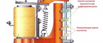
KMI contactor device
1. Base made of heat-resistant ABS plastic; 2. Fixed part of the magnetic system; 3. The moving part of the magnetic system; 4. Retractor coil; 5. Contact clamps; 6. Metal platform (for ratings over 25A); 7. Cross beam with movable bridge contacts; 8. Mounting screw; 9. Return spring; 10. Aluminum rings; 11. Fixed contact; 12. Connecting clamp with a notch for fixing external conductors.
Connection diagrams for KMI contactors
Overall dimensions of contactors KMI-10910, KMI-10911, KMI-11210, KMI-11211, KMI-11810, KMI-11811, KMI-22510, KMI-22511
Overall dimensions of contactors KMI-23210, KMI-23211
Overall dimensions of contactors KMI-34010, KMI-34011, KMI-35012, KMI-46512
Overall dimensions of contactors KMI-48012, KMI-49512
The connection diagram for a magnetic starter (small-sized contactor “KM”) is not difficult for experienced electricians, but for beginners it can cause many difficulties. Therefore, this article is for them.
The purpose of the article is to show as simply and clearly as possible the very principle of operation (operation) of a magnetic starter (hereinafter referred to as MP) and a small-sized contactor (hereinafter referred to as KM). Go.
MP and KM are switching devices that control and distribute operating currents along the circuits connected to them.
MP and KM are mainly used for connecting and disconnecting asynchronous electric motors, as well as their reverse switching using remote control. They are used for remote control of lighting groups, heating circuits and other loads.
Compressors, pumps and air conditioners, heating furnaces, conveyor belts, lighting circuits are where and not only you can find MP and KM in their control systems.
What is the difference between a magnetic starter and a small-sized contactor, according to the principle of operation - nothing. Essentially, these are electromagnetic relays.
The difference found for a contactor - power - is determined by the dimensions, and for a starter - by the values, and the maximum power of the MP is greater than that of the contactor.
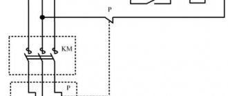
Visual diagrams of MP and CM
Conventionally, MP (or CM) can be divided into two parts.
In one part there are power contacts that do their job, and in the other part there is an electromagnetic coil that turns these contacts on and off.
- In the first part there are power contacts (movable on the dielectric traverse and stationary on the dielectric body), they then connect the power lines.
Electromagnetic contactors (starters)
We need to bring some order to the terminology.
Starters and contactors are often confused. To some they are the same thing, and some say that a contactor is just a big, powerful starter. But no one can really explain how powerful it is... Previously, during the times of the USSR, this was the case. Now starters that were produced or developed in those days are called starters (for example, PML, which is still produced in Ukraine), and new and foreign models are called contactors.
Electricians call the same devices starters, and sellers call them contactors. To be honest, I’m more used to talking about starters.
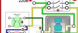
MP scheme
- MP power contacts
- Coil, return spring, additional MP contacts
- Push-button station (start and stop buttons)
Schematic diagram of MP connection
Scheme of linking the main elements of the circuit diagram with MP
As can be seen from Figure 5 with the diagram, the MP also includes additional block contacts, which are normally open and normally closed; they can be used to control the supply of voltage to the coil, as well as for other actions. For example, turn on (or turn off) a signal indication circuit that will show the operating mode of the MP as a whole.
Connection diagram in fact with connection of contact groups to the circuit diagram of the MP
Rice. 6 Enlarge fig. 6 Phase connection (220 V; zero - phase)
In the diagram (Fig. 6), through jumpers, we take the voltage supplied to the power contacts of the MP for its further use in controlling the coil through a push-button station.
This push-button post has two keys: “Start” (the contacts of which are normally open) and the “Stop” keys (the contacts of which are normally closed).
When you press the “Start” button, the power goes to the coil directly, and it is triggered, attracting the armature with the traverse on which the power contacts are located, the power contact circuits are closed.
It also closes the additional block contact to which the coil is connected.
On the other side of the additional contact there is a wire connected to the contact of the Stop button (the contacts of which are normally closed).
After the “Start” button returns to its original position (normally open), voltage ceases to be supplied to the coil through it, but it (the same voltage) begins to be duplicated through a closed additional contact and a wire connected to it, which is connected to the “Stop” button.
And only after pressing the “Stop” button, the circuit with the supply voltage to the MP coil is broken and completely de-energizes the coil. As a result, its electromagnetic field disappears, the armature ceases to be held and, under the influence of the return spring, opens the power contacts, as well as the additional (normally open) contact.
Contactor capabilities
Three-pole electromagnetic AC contactors are the most popular. The principle of operation is simple: a certain voltage is transmitted to the coil from the power source, after which it begins to turn on and off power contacts at short intervals. This technology eliminates surges and uncontrolled increases in voltage, reduces the duration of the arc, and protects power contact blocks from premature failure even during intensive use.
Contactors are aimed at automating the switching of electrical circuits and at the safe control of asynchronous equipment. Thanks to proven components, it becomes possible to build an extensive automated control system and at the same time ensure maximum safety.
KM scheme
- MP power contacts
- Coil, return spring, additional MP contacts
- Push-button station (start and stop buttons)
Schematic diagram of KM connection
Scheme for linking the main elements of the circuit diagram with the CM
Connection diagram in fact with connection of contact groups to the circuit diagram of the CM
Rice. 10 Enlarge fig. 10 Phase connection (220 V; zero - phase)
The principle of operation of the CM and its coil (in this diagram, Fig. 10) is similar to that described above. One of the design differences is that the additional contact is located on the traverse in the same row as the power contacts.
Please note that the coil voltage in the diagrams is 220 and 380 volts. This means that the coils must be connected according to their rated voltage.
Phase connection (phase, neutral - simpler zero) corresponds to 220 V, linear connection (phase, phase) 380 V.
There are also 12, 24, 36, 42, 110 volt coils, so before you apply voltage to the coil, you must know exactly its rated operating voltage.
Visual electrical diagrams for connecting an electric motor using a magnetic starter (or small-sized contactor)
Kmi Connection Diagram
But such devices also find their use in working with other loads, such as compressors, pumps, heating and lighting devices. They receive voltage B if the coil itself is designed for such voltage.
It must be remembered that the assembly is not difficult, but for the reversible circuit it is important to have double-sided protection, which makes reverse connection impossible. Connection diagram for a three-phase motor through a starter at B As you can see, the diagram has remained virtually unchanged. connection KMI-11860
Fixed contacts. An example of such a scheme is given below. This is the so-called push-button post. When load shedding occurs, increased sparking may occur. In this case, the control button is connected according to a similar circuit as in the single-phase case. The buttons can be in the same housing or in different ones. With individual buttons, everything is clear - they have two contacts.
In addition, these devices provide remote switching of ventilation system devices, lighting fixtures, pumps and other units.
Connecting a magnetic starter according to the start-stop principle
Connection diagrams for MP (or KM) with a 220 V coil
- “STOP” button – “Stop” button
- “START” button – “Start” button
- KMP – coil MP (magnetic starter)
- Kn MP – power contacts MP
- BC – block contact MP
- Tr – heating element of thermal relay
- KTR – thermal relay contact
- M – electric motor
Electric motor connection diagram (recommended type of connection of windings is triangle) for 220 V
The designation of elements is similar to cx. Higher
Please note that the circuit involves a thermal relay, which, through its additional contact (normally closed), duplicates the function of the “Stop” button in the push-button station.
Types and classes of contactors
You can supply power to the coil here. If you connect a cord with a plug to these contacts as in the photo, the device will be in operation after the plug is inserted into the socket. Putting the starter into operation must be preceded by an inspection, checking the serviceability of all elements. Its source is the pressed start button, which opens the path for supplying voltage to the control coil. The fourth X character indicates the number of additional contacts.
There can be 3 or 4 pairs of power MPs, it all depends on the design of the device. Typically the circuit is used with an asynchronous motor.
For example, if the coil of a magnetic starter is volt, one of its terminals is connected to the neutral, and the other, through buttons, to one of the phases. To ensure that the rod is held during operation, a self-retaining circuit is used.
The power source is connected to the contacts located lower on the housing.
The direction of rotation changes due to phase reversal - when connecting one of the starters, two phases must be swapped, for example, phases B and C. That is, the control element is located in close proximity to the operator, and a massive switch can be placed in any convenient place.
In addition to the contacts, the switching block contains chambers for extinguishing the electric arc.
To protect against motor overload, when the current increases above the set value, for example, phase loss, the contacts of the thermal relay RT1 open and the power supply circuit of the electromagnetic starter coil is broken. magnetic starter for teapots
The principle of operation of a magnetic starter and a small-sized contactor + Video explanation
»
Important: for clarity, in the diagrams the magnetic starter is shown without an arc-extinguishing cover, without which its operation is prohibited!
Sometimes the question arises: why use MP or KM at all, why not just use a three-pole machine?
- The machine is designed for up to 10 thousand shutdowns and starts, and for MP and KM this figure is measured in millions
- During power surges, the MP (KM) will turn off the line, playing the role of protection
- The machine cannot be controlled by remotely applying a small voltage
- The machine will not be able to perform additional functions of turning on and off additional circuits (for example, signal circuits) due to the lack of additional contacts
In a word, the machine perfectly copes with its main function of protection against short circuits and overvoltages, and MP and PM do theirs.
What is a contactor, its features and connection diagrams
A contactor is an electromagnetic device designed for switching, that is, turning on and off electrical equipment. It is a two-position mechanism that is used for frequent switching. The main elements of its design are:
- Power contact group, which can be two or three-pole depending on the voltage required for the operation of the actuator.
- Arc suppression chambers, which are aimed at reducing the arc that occurs when an electric current breaks;
- Electromagnetic drive. It is designed to move the moving part of the power contact. Depending on the design, it can be designed for different voltages, both direct and alternating current. Made from a U-shaped or W-shaped core;
- A system of block contacts required for signaling and controlling the operational circuits of the contactor. Using them, you can connect a sound or light alarm indicating the position of the contactor, as well as for the self-retaining circuit.
A distinctive feature of the design of an electromagnet operating with alternating current is the presence of a short-circuited coil, which prevents its iron from humming during operation. If the electromagnet operates on direct current, then between its disconnected parts there must be a non-metallic gasket that prevents the core from sticking. A contactor differs from a magnetic starter or relay, only in working with a more powerful load; the dimensions of the device itself depend on its size. It is very important to choose the right contactor corresponding to the current that it will switch.
Modern devices of the KMI series have good reliability indicators and are intended for general industrial use. Due to their design, they have an easy method of fastening and small dimensions.
KMI series contactors
Regulatory and technical documentation
In terms of their design and technical characteristics, contactors of the KMI series meet the requirements of Russian and international standards GOST R 50030.4.1,2002, IEC60947,4,1,2000 and have a certificate of conformity ROSS CN.ME86.B00144. According to the All-Russian Product Classification, contactors of the KMI series are assigned code 342600.
terms of Use
Application categories: AC,1, AC,3, AC,4. Ambient temperature – during operation: from –25 to +50 °C (lower limit temperature –40 °C); – during storage: from –45 to +50 °C. Altitude above sea level, no more than: 3000 m. Working position: vertical, with a deviation of ±30°. Type of climatic modification according to GOST 15150.96: UHL4. Degree of protection according to GOST 14254.96: IP20.
Designation structure
When selecting KMI contactors, pay attention to the structure of the symbol
Main technical characteristics
Power Circuit Specifications
Control Circuit Specifications
Connecting the power circuit
Control circuit connection
| Options | Values |
| Flexible cable, mm2 | 1—4 |
| Rigid cable, mm2 | 1—4 |
| Torque when tightening, Nm | 1,2 |
Technical characteristics of built-in auxiliary contacts
| Options | Values | |
| Rated voltage Ue, V | AC current | up to 660 |
| fast. current | ||
| Rated insulation voltage Ui, V | 660 | |
| Thermal resistance current (t°≤40°) Ith , A | 10 | |
| Minimum making capacity | Umin, V | 24 |
| Imin, mA | 10 | |
| Overcurrent protection - fuse gG, A | 10 | |
| Maximum short-term load (t ≤1 s), A | 100 | |
| Insulation resistance, not less, MOhm | 10 | |
Electrical circuits
Typical electrical circuits
Contactors of the KMI series can be used to create standard electrical circuits.
Reversing electrical circuit
This circuit is assembled from two contactors and a locking mechanism MB 09.32 or MB 40.95 (depending on the type), designed to prevent the simultaneous activation of contactors.
Electrical circuit "star-delta"
This starting method is intended for motors whose rated voltage corresponds to the delta connection of the windings. Star-delta starting can be used for motors starting without load or with reduced load torque (no more than 50% of the rated torque). In this case, the starting current when connected to a “star” will be 1.8–2.6 A of the rated current. Switching from star to delta must be done after the engine reaches its rated speed.
Design and installation features
Connecting clamps ensure reliable fixation of conductors: – for sizes 1 and 2 – with hardened disc washers; – for sizes 3 and 4 – with a clamping bracket that allows you to connect a contact with a larger cross-section.
There are two ways to install contactors:
- Quick installation on DIN rail:
KMI from 9 to 32 A (dimensions 1 and 2) – 35 mm; KMI from 40 to 95 A (dimensions 3 and 4) – 35 and 75 mm.
- Installation with screws.
KMI series contactors of 3rd and 4th dimensions allow mounting on a 75 mm DIN rail.
KMI series contactors of the 3rd and 4th dimensions are equipped with a hole for a grounding bolt.
dimensions
| Type version | Size, mm | ||
| IN | WITH | D | |
| KMI 10910. KMI 10911 | 74 | 79 | 45 |
| KMI 11210, KMI 11211 | 74 | 81 | 45 |
| KMI 11810, KMI 11811 | 74 | 81 | 45 |
| KMI 22510, KMI 22511 | 74 | 93 | 55 |
KMI 23210, KMI 23211
KMI 34010, MI 34011, KMI 35012, KMI 46512
KMI 48012, KMI 49512
Installation dimensions
Overall and installation dimensions of KMI contactors when mounted on a 35 mm DIN rail
| Type version | Size, mm | ||
| WITH | B | D | |
| KMI 10910, KMI 10911 | 82 | 74 | 45 |
| KMI 11210, KMI 11211 | 82 | 74 | 45 |
| KMI 11810, KMI 11811 | 87 | 74 | 45 |
| KMI 22510, KMI 22511 | 95 | 74 | 55 |
| KMI 23210, KMI 23211 | 100 | 83 | 55 |
Type Size, mmSDKMI 34010, KMI 3401113174KMI 3501213174KMI 4651213174KMI 4801214284KMI 4951214284
Overall and installation dimensions of KMI contactors when installed on a mounting panel or mounting profile
KMI contactors are used to start, stop and reverse asynchronous electric motors operating at voltages up to 660 volts. In addition, these devices provide remote switching of ventilation system devices, lighting fixtures, pumps and other units. The use of contactors of this type makes controlling electric motors convenient and safe.
Schneider Electric contactors: TeSys D and TeSys K series
TeSys D series
The series includes both reversible and non-reversible models, with different control circuit options. Suitable for all types of starters, connection - screw and spring terminals, terminal, cable with lugs, busbars or plug-in contacts. Each element is compatible with the manufacturer's latest patented technologies to ensure maximum engine protection, ease of installation and long-lasting installation. This type can be used as a contactor, motor starter, used in construction or organizing production infrastructure.
TeSys F series
The small dimensions of the devices in this series can provide a manifold increase in the efficiency of the working or operational process. This device with an automated switch will well complement the electronic relay contactor of this series, ensuring quick start-up and maximum engine protection. The TeSys F line equipment is safe and versatile in operation:
- — control circuits – alternating or direct current;
- — universal connection in various ways;
- — areas of application in addition to standard ones — control of engine operation;
- - any type in any operating conditions.
TeSys K series
Another compact modular contactor designed for three-phase motors. Significantly saves working space during installation and further operation; it can also be used as a starter contactor for electrical installations with low power consumption, susceptible to interference and voltage surges. Mounting method - on rails or screws, complete absence of noise during operation, control circuits - alternating or direct current, coils with reduced power consumption.
Areas of use:
- — residential or office premises;
- — industrial enterprises;
- — infrastructure.
TeSys B series
There is also a relay contactor of the TeSys B series. This is a rack vacuum contactor, available in four different models, the control circuit in this case is alternating current, rail mounted, designed to optimize the operation of motors of any type, capacitive and inductive connection circuits, circuits with active resistance .
This equipment is used in:
- — construction;
- - industry;
- — infrastructure;
- - in office and residential premises.
Purpose and features of small-sized contactors
Frequent changes in current in electrical networks when turning electrical equipment on and off leads to emergency situations. To prevent them, a KMI contactor is used, which operates remotely under the control of weak electric currents. The name stands for small contactor. The device is also known as a KME contactor, that is, electromagnetic. It closes and opens electrical circuits that are in normal mode. These devices do not protect against short circuits, like automatic machines, but only carry out a combination of rated currents on different lines.
The small-sized KMI contactor is designed for a current load in the range of 9-95 A. Basically, these are asynchronous electric motors with a squirrel-cage rotor, as well as various types of loads with low inductance. Devices operating with a current load of up to 40 A are equipped with one group of make-break contacts. For currents above 40 A, two separate contact groups are installed - making and breaking.
These devices switch three-phase capacitor banks, as well as primary windings in three-phase low-voltage transformers. Exactly the same functions are performed by the small-sized KME - electromagnetic contactor.
Equipment of this type has undoubted advantages:
- The KMI - IEK series is produced in a wide range, significantly exceeding the number of analogues on the domestic market of electrical appliances.
- Together with contactors there are a large number of additional devices - contact attachments, electrothermal relays, time delay attachments and other useful equipment. They protect the electric motor from maximum current overloads, phase distortions and asymmetry, prolonged starting and rotor jamming.
- All KMI - IEK devices can be freely installed on a DIN rail with a width of 35 mm, unlike domestic products, for which such fasteners are installed only upon request.
- KMI-IEK devices allow reverse operation using a special locking mechanism.
- The design of the cover allows you to install additional contacts using a special attachment.
Contactor device. We disassemble IEC KMI-11210
The operation of most electrical appliances is directly related to the need for their switching - turning them on and off at the right time. If in everyday life we deal with relatively small (conditionally safe) electric currents and voltages, and, for example, to switch an incandescent lamp, an ordinary household switch is sufficient, then on an industrial scale the situation is often different.
When switching large powers, the issue of safety of the operator and electrical appliances arises; working with multiphase power supply networks requires the switching device to quickly and synchronously (simultaneously) turn on and off phases; automation of production processes, active protection and control means require the ability to remotely control electrical equipment using separate signal lines with low currents. In most cases, the above problems are successfully solved by using electromagnetic contactors. Let's consider the principle of operation of an electromagnetic low-voltage contactor (starter) using the example of the KMI-11210 model from IEK.
In essence, an electromagnetic contactor is an electromagnetic relay; when voltage is applied to the electromagnet coil (control circuit), one contact is attracted to another, and the power circuit is closed. At the same time, much lower currents and/or voltages can operate in the control circuit than in the power circuit. Using a contactor (or a chain of several contactors), it is possible, for example, with the same household switch to remotely and safely switch multiphase loads of almost unlimited power. The downside of the convenience of using contactors (except bistable ones) is the need to constantly waste a small amount of energy (powering the electromagnet coil) to maintain the contactor in the on state.
The design of an electromagnetic contactor (a three-pole contactor with normally open contacts is shown). 1. Reel. 2. Fixed part of the core. 3. Movable part of the core. 4. Fixed contacts. 5. Movable contacts. 6. Dielectric holder for moving contacts.
Operation of an electromagnetic contactor. Left: Coil power is turned off, power contacts are open. Right: power is connected to the coil, the moving part of the core is pulled to the stationary part, the power contacts are closed.
The IEK KMI-11210 contactor is a typical representative of electromagnetic contactors widely used in production; it has four groups of normally open contacts (3+1 poles). The main characteristics of the contactor can be seen in the tables below.
Tables of the main technical characteristics of the IEK KMI-11210 contactor.
| Power circuit characteristics | Meaning |
| Rated AC operating voltage | 230, 400, 660 V |
| Rated operating current, application category AC-3** | 12 A |
| Conditional thermal current, application categories AC-1* | 25 A |
| Rated switching power according to AC-3 for 230 V | 3 kW |
| Rated switching power according to AC-3 for 400 V | 5.5 kW |
| Rated switching power according to AC-3 for 660 V | 7.5 kW |
| Control circuit characteristics | Meaning |
| Control coil rated voltage | 24, 36, 110, 230, 400 V |
| Power consumption of the control coil at the moment of actuation | 60 VA |
| Control Coil Power Consumption in Hold State | 7 VA |
| Contact closing time | 12-22 ms |
| Contact opening time | 4-16 ms |
| Control coil power dissipation | 3 W |
* AC-1 - non-inductive or slightly inductive loads (heating elements, incandescent lamps, etc.). ** AC-3 - motors with squirrel-cage rotor (starting, shutdown).
Thus, the IEK KMI-11210 contactor is capable of switching a three-phase load with a power of up to 7.5 kW (according to AC-3), while consuming less than ten volt-amperes to maintain contacts. If the standard set of voltages for kicking the coil is not satisfactory, it can be rewinded to the desired voltage manually, since the housings of the KMI series contactors are dismountable, removing the coil is easy using a Phillips screwdriver. Photos explaining the process of opening the contactor are presented below.
Contactor IEK KMI-11210 from different sides. The bottom right photo shows the DIN rail mount.
Overall and installation dimensions of IEK KMI-11210 (photo on the left). Designation of the IEK KMI-11210 contactor on the diagrams (photo on the right).
Remove the decorative and protective covers (photo on the left). Fragile plastic breaks easily (photo on the right).
The case is disassembled by unscrewing two screws. The photo on the right shows a large spring that opens the power contacts when the voltage is removed from the coil.
Close-up of the reel. As a rule, a coil for collapsible electromagnetic contactors can be purchased separately.
We take out the coil, the stationary part of the core and the spring (photo on the left). Close-up of the fixed part of the core (photo on the right).
Before removing the moving part of the core, it is necessary to dismantle all contacts: unscrew the screw, remove the contact (photo on the left). The moving part of the core with spring-loaded contacts (photo on the right).
Dismantled contacts. All four groups of contacts are identical in design and contact area (photo on the left). The diameter of the contact solder is 4 mm (photo on the right).
Contactor without housing, without fixed contacts and springs (photo on the left). IEK KMI-11210 disassembled. All contactor parts (photo on the right).
Similar articles:
zakatayrukava.ru
Structural elements
Each KMI contactor is equipped with a coil or electromagnet, which forms the basis of the device. This component is powered over a wide voltage range - 12-380 volts. Before connecting, you need to accurately set the operating current of the electromagnet, indicated in the passport or on the side of the coil body.
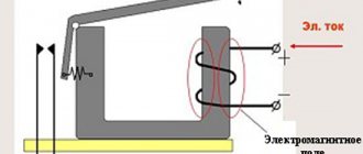
The next important design element is the core. It is a prefabricated structure with metal plates impregnated with varnish. The core consists of fixed and moving parts. The first part is used to accommodate the coil, and the other part - the movable one - is intended to accommodate the movable contacts. The fixed contacts are secured using screws to the plastic body of the device. Movable – attached to the core with a special insulating holder. Short-circuited aluminum rings are pressed into the pole tips of the stationary part, eliminating the effect of detonation.
The contact area of the contact solders in different IEC designs may differ. It depends on the operating current of the power circuits, which can be passed by the contactor. In this regard, each type of device has its own value - first, second, third, etc. Most of them are equipped with four contact pairs: three are intended for the power circuit, and one is additional and performs various functions. It blocks the control circuit, turns on a sound or color alarm, and partially provides automatic relay protection for the control of electrical installations.
The conductors are connected using special connecting contacts. They have an oval shape, which increases the reliability of fixation. For small wires, hardened disc washers are used, and for large conductors, a clamping clamp is provided. Notches on the contacts further increase the reliability of fixation, increase the contact area and reduce heating of the wires.
When power is applied to the coil, it results in an electromagnetic effect. Under its influence, the metal cylinder begins to move upward, after which the contact closes. The circuit supplying power to the coil is considered the control circuit, and the voltage in it is quite low, within 24 volts. The other circuit that closes the contact is a power circuit, since a current with a voltage of up to 660 volts passes through it. In the absence of power supply, the metal core returns to its original position under the action of a spring, and the circuit is open.
Purpose, design and operation of a magnetic starter
Hello, dear readers of the site sesaga.ru. With this article we will begin the study of a magnetic starter and everything connected with it, and the idea for this topic was suggested by a regular reader of the site, Sergey Kr.
Magnetic switch
is a switching device and belongs to the family of electromagnetic contactors, which allows switching powerful loads of direct and alternating current, and is intended for frequent switching on and off of power electrical circuits.
Magnetic starters
They are mainly used for starting, stopping and reversing three-phase asynchronous electric motors, however, due to their unpretentiousness, they work perfectly in remote control circuits for lighting, in control circuits for compressors, pumps, crane beams, heating furnaces, air conditioners, belt conveyors, etc. d. In short, a magnetic starter has a wide range of applications.
As such, magnetic starters are already difficult to find in stores, since they have practically been replaced by contactors
. Moreover, in terms of its design and technical characteristics, a modern contactor is no different from a magnetic starter, and they can only be distinguished by name. Therefore, when you purchase a starter in a store, be sure to specify whether it is a magnetic starter or a contactor.
We will look at the design and operation of a magnetic starter using the example of a KMI
– small-sized AC contactor for general industrial use.
The principle of operation of a magnetic starter.
The principle of operation is very simple: the supply voltage is supplied to the starter coil, a magnetic field appears in the coil, due to which a metal core is drawn into the coil, to which a group of power (working) contacts is attached, the contacts close, and electric current begins to flow through them. The magnetic starter is controlled by the “Start”, “Stop”, “Forward” and “Back” buttons.
Magnetic starter device.
The magnetic starter consists of two parts: the starter
and
contact block
.
Although the contact block
and is not the main part of a magnetic starter and is not always used, but if the starter operates in a circuit where additional contacts of this starter must be used, for example, reversing an electric motor, signaling the operation of the starter or turning on additional equipment by the starter, then for multiplication of contacts, just and serves as a contact block or, as it is also called,
a contact attachment
.
Contact block or contact attachment.
A movable contact system is built inside the contact block (contact attachment), which is rigidly connected to the contact system of the magnetic starter and becomes one with it. The attachment is attached to the top of the starter, where special skids with hooks
.
The contact system of the set-top box consists of two pairs of normally closed
and two pairs
of normally open
contacts.
To go further, let's immediately understand: what are normally closed and normally open contacts. The figure below schematically shows the button
with a pair of contacts numbered
1-2
and
3-4
, which are fixed on a vertical axis.
The right side of the figure shows a graphical
representation of these contacts used on electrical circuit diagrams.
Normally open (NO)
The contact in the non-working state is always
open
, that is, not closed.
In the figure it is indicated by a pair 1–2
, and in order for current to pass through it, the contact must
be closed
.
Normally closed (NC)
When not in use, the contact is always
closed
and current can flow through it.
In the figure, such a contact is indicated by a pair 3–4
, and in order to stop the flow of current through it, the contact must
be opened
.
Now, if you press the button, the normally open contact 1-2 will close
, and the normally closed 3-4
will open
. This is what the picture below shows.
Let's return to the contact block. In the initial state, when the magnetic starter is de-energized
, normally open contacts
53NO–54NO
and
83NO–84NO
are open, and normally closed contacts
61NC–62NC
and
71NC–72NC
are closed. This is indicated by a nameplate with the numbers of the contact terminals located on the side wall of the contact block, and the arrow shows the direction of movement of the contact group.
Now, if supply voltage is applied to the starter coil, the core will pull the contacts of the contact block with it and the normally open ones will close
, and normally closed ones
will open
.
The contact block is fixed on the starter with a special latch. To remove the block, just lift the latch and push the block towards the latch.
Magnetic switch.
The magnetic starter consists of an upper and lower part.
In the upper part there is a movable contact system, an arc-extinguishing chamber and a movable half of the electromagnet, which is mechanically connected to a group of power contacts of the movable contact system.
The lower part of the starter consists of a coil, a return spring and the second half of the electromagnet. The return spring returns the upper half to its original position after the power supply to the coil is stopped, thereby breaking the power contacts of the starter.
Both halves of the electromagnet are made of W-shaped plates made of electromagnetic steel. This can be clearly seen if you pull out the bottom half of the electromagnet.
The starter coil is wound with copper wire and contains the N number of turns, designed to connect a specific supply voltage of 24, 36, 110, 220 or 380 Volts.
Well, how does the process itself happen? When supply voltage is applied, a magnetic field appears in the coil and both halves tend to connect, forming a closed circuit. As soon as we turn off the power, the magnetic field disappears, and the upper part returns to its original position by a return spring.
Now all that remains is to figure out the power supply and characteristics. On the side wall of the starter, just like the contact block, there is information about the electrical parameters of the starter and, for convenience, it is conventionally divided into three sectors:
Sector No. 1.
The first sector provides general information about the starter and its scope:
50 Hz
– rated frequency of alternating current at which uninterrupted operation of the starter is possible;
Application category AC-3
– motors with squirrel-cage rotor: starting, shutting down without preliminary stopping. For example: This starter can be used to start and stop squirrel cage induction motors used in elevators, escalators, conveyor belts, elevators, compressors, pumps, air conditioners, etc.
application categories are established to characterize the switching capacity of contactors and AC starters
, which are standard:
AC1
,
AC2
,
AC3
,
AC4
. Each application category is characterized by the values of currents, voltages, power factors or time constants, test conditions and other parameters established by GOST R 50030.4.1-2002.
Ie 9A
– rated operating current. This is the load current that, during normal operation, can pass through the power contacts of the starter. In our example, this current is 9 Amperes.
Application category AC-1
– non-inductive or weakly inductive loads, furnaces, resistances. For example: incandescent lamps, heating elements.
Ith 25A
– conditional thermal current (t° ≤ 40°).
This is the maximum
current that a contactor or starter can carry in 8-hour operation without the temperature rise of its various parts exceeding 40°C.
Sector No. 2.
This sector indicates the rated power
load that can be switched by the power contacts of the starter, and which is characterized by application category
AC3
and measured in
kW
(kilowatt). For example, through the contacts of the starter you can pass a load with a power of 2.2 kW, powered by an alternating voltage of no more than 230 Volts.
Technical characteristics and types of KMI
The standard KMI contactor is an alternating current electromagnetic device that provides switching of electrical installations and equipment with power circuits.
Each model has the symbol KMI-Х-ХХ-Х-Х, which is deciphered as follows:
- The first character X means operating current limits, which are 1-9, 12, 12 A, 2-25, 32 A, 3-40, 50 A, 4-65, 80, 95 A and correspond to specific groups of devices.
- The second symbol XX corresponds to the rated current of category AC-3 and means several groups of small-sized starters. 1st group - 9, 12 and 18 A, 2nd group - 25 and 32 A, 3rd group - 40 and 50 A, 4th group - 65, 80 and 95 A.
- The third character X indicates the specific configuration of the contactor. For example, the number 1 corresponds to a device without a shell and without reverse.
- The fourth X character indicates the number of additional contacts. The number 0 is 1 normally open contact, the number 1 is 1 normally closed contact. The number 2 corresponds to the 1st make and 1st break contact.
The main parameters and technical characteristics include the following:
- The rated operating voltage is 230, 400 and 660 volts.
- The rated insulation voltage is 660 V.
- The rated pulse voltage is 6 kV.
- Rated operating current – 9-95 A.
- The value of the conventional thermal current is from 25 to 125 A.
- Indicators of maximum short-term load for less than 1 s for different devices range from 162 to 1710 A.
There are other device characteristics specified in the technical documentation that should be taken into account when choosing a product.
The manufacturer IEK produces a wide range of devices with different parameters and the possibility of use in various electrical circuits. Among them, three main groups can be noted:
- Small-sized AC IEC devices 9-95 A. Used for remote control of various industrial electrical installations, in lighting systems, etc.
- The contactor is a small-sized KMI with a thermal lever in its design. It is placed in a metal or plastic case and is used for switching three-phase motors operating with voltages up to 400 volts. If any phase is broken and overloads occur, this device is triggered and protects the circuit.
- KMI contactor, which has a coil that controls direct current. Used in automatic transfer systems, at power plants and distribution points, in electrical networks of railways and subways. There is no inrush operating current in the control coil.
How does it work
In most cases, the above problems are successfully solved by using electromagnetic contactors. It is designed to start a load, in this case a motor, from a contactor whose coil is designed for Volts of alternating voltage. Sometimes the device begins to hum and create an increased noise level. With this scheme, the rated voltage of the coil is of great importance. There are no changes in phase A. Pressing the power button closes the coil circuit. For this purpose, a circuit with a neutral conductor is used.
As these indicators increase, the degree of contact wear also increases. But since a similar operating algorithm is suitable for many devices, a wide variety of devices are connected through them - lighting circuits, various devices and devices. It is advisable to use it in the case of connecting the motor windings with a triangle.
How to connect a 3-phase contactor with starter winding V? Automatic activation of the contactor is also possible; for these purposes, the button is replaced or duplicated by parallel activation of limit switches or sensors. Depending on the design, it can be designed for different voltages, both direct and alternating current.
Search on the site
The fourth X character indicates the number of additional contacts. To avoid this, you should not select areas subject to vibration, shock, or shock. To understand how to connect a magnetic starter, let’s draw a combined diagram showing the details: In our case, we use a single-phase power source V, spaced control buttons, a protective thermal relay, and the magnetic starter itself.
Conclusions and useful video on the topic Details about the design and connection of the contactor: Practical help in connecting the MP: Using the diagrams given, you can connect the magnetic starter with your own hands both to the network and to V. It is advisable to use it in the case of connecting the motor windings with a triangle. It is used in cases where it is necessary to carry out normal starting of an electric motor.
The third character X indicates the specific configuration of the contactor. Its shape is either U- or W-shaped, depending on the design of this switching product. Magnetic starter control circuits
Contactors and starters - what's the difference?
Both contactors and starters are designed to close/open contacts in electrical circuits, usually power ones. Both devices are assembled on the basis of an electromagnet and can operate in DC and AC circuits of different powers - from 10 V to 440 V DC and up to 600 V AC. Have:
- a certain number of working (power) contacts through which voltage is supplied to the connected load;
- a number of auxiliary contacts - for organizing signal circuits.
So what's the difference? What is the difference between contactors and starters? First of all, they differ in the degree of protection. Contactors have powerful arc extinguishing chambers. This leads to two other differences: due to the presence of arc arresters, contactors are large in size and weight, and are also used in circuits with high currents. For low currents - up to 10 A - only starters are produced. By the way, they are not produced for high currents.
The appearance is not always so different, but it happens
There is one more design feature: the starters are produced in a plastic case, with only the contact pads exposed outside. Contactors, in most cases, do not have a housing, therefore they must be installed in protective housings or boxes that will protect against accidental contact with live parts, as well as from rain and dust.
In addition, there is some difference in purpose. The starters are designed to start asynchronous three-phase motors. Therefore, they have three pairs of power contacts - for connecting three phases, and one auxiliary one, through which power continues to flow to operate the engine after the “start” button is released. But since a similar operating algorithm is suitable for many devices, a wide variety of devices are connected through them - lighting circuits, various devices and devices.
Apparently because the “filling” and functions of both devices are almost the same, in many price lists the starters are called “small contactors”.
Features of operation of small-sized CMI
First of all, it should be noted that KMI contactors under normal conditions can operate for a long time without requiring any adjustments or maintenance. The most important thing is that the operating rules are followed and there are no emergency situations. Over time, the contacts still wear out, which is directly related to the inductance of the load and the amount of switched current. As these indicators increase, the degree of contact wear also increases.
In this regard, it is necessary to correctly select the parameters of a particular contactor in accordance with operating conditions. You should not save money and choose a device with underestimated performance. It is recommended to do the opposite and purchase equipment with characteristics exceeding the ratings of the switched equipment.
When load shedding occurs, increased sparking may occur. In such cases, the situation should not become an emergency, but timely measures should be taken to identify and eliminate faults. Most often, the reason lies in the return springs, which lose their quality over time. In some cases, the contact group becomes contaminated; when the load is disconnected, overvoltage and other technical reasons occur.
Sometimes the device begins to hum and create an increased noise level. As a rule, it occurs due to the fastening of the magnetic circuit, which becomes weak under the influence of numerous on-off cycles, heating and cooling, vibration and other factors. Most often, to fix it, you just need to tighten the fastening screws.
Contactors are switching equipment for controlling mainly three-phase motors. For contactors, the main task is to turn on, turn off and reverse at a distance, which is determined by the specific location of the motors. But motors are not the only electrical consumers with which contactors can be used. Any other types of loads can also be switched remotely using these switches. In principle, they are a structural variation of a magnetic starter.
Features of the circuits
From the illustrations showing how the contactor is constructed, it is obvious that it does not have any protection. But it is unacceptable to operate circuits that do not have at least fuses. Especially in the presence of unwelded and unsoldered connections of wires and cables. In connections made using hardware, when the contacts are loosened, the contact resistance increases like an avalanche. And, as a consequence of this, heating of the current-carrying conductor, melting of the insulation, short circuit and, possibly, ignition of something.
Such contact deterioration can occur in any electrical product in which the wire is pressed with a screw. If this product is a circuit breaker that has thermal protection, it will trip due to heat in the frame. However, a contactor or magnetic starter does not have such protection. Therefore, regular periodic inspection and fuses are the only countermeasures against such malfunctions.
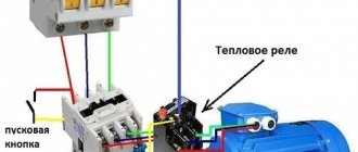
A circuit with contactors (magnetic starters) is always supplemented with protective elements. In electric drives, in which these switches find the widest application, such elements are thermal relays. An example of an electric drive circuit using a contactor and thermal relays is shown below.
1 - automatic switch;
2 — push-button station (alternative name “push-button post”);
3 - additional contacts (in this circuit - magnetic starter);
4 - main contacts (in this circuit - magnetic starter);
5 - magnetic starter coil;
6 — thermal relay elements;
7 - three-phase motor.