A magnetic starter is a device designed for switching power electrical circuits. The first thing you need to do before servicing or repairing a magnetic starter is to study the documentation for this starter, or, as they do in the 21st century, look it up on the Internet. It is also worth knowing the weak points of magnetic starters - contact groups. It is the contact groups that need careful examination. It is worth paying attention to the fastening elements and the body, which will be discussed in the article.
Visual inspection
Repair of a magnetic starter begins with an external inspection. An external inspection involves inspecting the body and fastening elements for cracks and chips. If there are cracks on the fastening elements, this affects the volume of operation, and also, if the starter falls off and its “toad” design, then there is a danger that it will turn on the power circuit. In addition, it is worth paying attention to protective covers.
It is also worth inspecting the starter for contamination. If there is a large amount of dust, oil, traces of liquid (crystalline growths) and other aggressive elements on the housing, then it is worth reconsidering the method of protecting the starter from aggressive environmental influences. Increase the degree of dust and moisture protection. If this is not done, the coil in the starter, which will be described below, will quickly become damp and fail, and the metal parts will become corroded.
Contact groups
Basically, maintenance and repair of magnetic starters comes down to contact groups. To inspect them, you need to open the protective cover; the first thing we pay attention to is the contact groups. If there is slight carbon deposits, you need to clean it off with fine-grain sandpaper. As you can see in the photo, there is no oxidation. This means that the chosen method of protecting the starter from aggressive environmental factors is chosen correctly.
If traces of oxide, darkening, or rust are visible on the metal parts, then in this case it is necessary to definitely reconsider the method of installing the starter. Or rather, install it in a more dust- and moisture-proof shell. Then we inspect the contact groups for the presence of carbon deposits, deposits, and cavities. Depending on the degree of damage to the contact groups, a decision is made on repair or replacement.
Connection diagrams
What is a magnetic starter used for? Mainly for organizing the safe connection (and control) of asynchronous three-phase motors. Therefore, we will consider options for the operation of the circuit under various conditions. In all illustrations there is a protective relay indicated by the letter “P”. Bimetallic plates that activate the emergency switch (installed in the control circuit) are located on the power lines of the contact group. They can be placed on one or more phase conductors. If there is overheating (it occurs when the load is exceeded or a simple short circuit), the control line breaks and power is not supplied to the “KM” coil. Accordingly, the power contact groups “KM” open.
Classic circuit for direct connection of a three-phase electric motor
The control circuit uses power from the voltage between two adjacent phase lines. When you press the “Start” button, the “KM” coil circuit is closed using its main contact. In this case, all contact groups, including additional contacts in the control circuit, are connected under the control of the coil electromagnet. There are two ways to open the circuit: when the emergency relay is activated, or by pressing the “Stop” button. In this case, the magnetic starter returns to its original “all off” position (or in the case of two categories of contacts, the normally closed groups will be connected).
The same connection option, only the control circuit is connected to the phase and neutral. From the point of view of starter operation, there is no difference. The buttons and the protective thermal relay work in the same way.
Reversible connection of a three-phase electric motor
As a rule, two electromagnetic starters are used for this, in which the outputs of the phase contacts are combined with a shift. The devices are combined into one switch, so it can be considered as a single element.
Depending on which contact group is connected to the electric motor, its rotor rotates in one direction or the other. This option is indispensable when used on conveyors, machine tools, and other electrical installations that provide 2 directions of rotation (movement).
How does this scheme work in practice? Let's look at the illustration:
A single control scheme with two groups of start buttons: “Forward” and “Back”. Each of them includes a corresponding electromagnet coil. Why is the scheme common? According to safety conditions, the “Stop” button should be uniform. Otherwise, if an emergency occurs, the operator will lose precious seconds searching for the required button (for “Forward” or for “Back”).
Example of faulty moving contacts that must be replaced
The photo above shows a contact that “survived” after a short circuit. The remaining two have failed and need to be replaced.
Repair of contactors and magnetic starters often comes down to repair of contact groups. This is done by cleaning carbon deposits from the contact pad. If shells and build-ups are found during inspection, then these places need to be leveled with a flat, small file or needle file. This is done in the same plane as the contact pad of the fixed contact. To ensure a better effect, you can grind both contact pads on the moving and fixed elements.
It is highly not recommended to do all these operations with sandpaper or sandpaper, since in this case it is very difficult to maintain a flat surface. An unmaintained plane means a decrease in the contact area, and this in turn causes excessive heating and premature failure of the magnetic starter. It is worth inspecting both the main and auxiliary contact groups.
The operation of most electrical appliances is directly related to the need for their switching - turning them on and off at the right time. If in everyday life we deal with relatively small (conditionally safe) electric currents and voltages, and, for example, to switch an incandescent lamp, an ordinary household switch is sufficient, then on an industrial scale the situation is often different.
When switching large powers, the issue of safety of the operator and electrical appliances arises; working with multiphase power supply networks requires the switching device to quickly and synchronously (simultaneously) turn on and off phases; automation of production processes, active protection and control means require the ability to remotely control electrical equipment using separate signal lines with low currents. In most cases, the above problems are successfully solved by using electromagnetic contactors. Let's consider the principle of operation of an electromagnetic low-voltage contactor (starter) using the example of the KMI-11210 model from IEK.
In essence, an electromagnetic contactor is an electromagnetic relay; when voltage is applied to the electromagnet coil (control circuit), one contact is attracted to another, and the power circuit is closed. At the same time, much lower currents and/or voltages can operate in the control circuit than in the power circuit. Using a contactor (or a chain of several contactors), it is possible, for example, with the same household switch to remotely and safely switch multiphase loads of almost unlimited power. The downside of the convenience of using contactors (except bistable ones) is the need to constantly waste a small amount of energy (powering the electromagnet coil) to maintain the contactor in the on state.
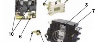
The design of an electromagnetic contactor (a three-pole contactor with normally open contacts is shown). 1. Reel. 2. Fixed part of the core. 3. Movable part of the core. 4. Fixed contacts. 5. Movable contacts. 6. Dielectric holder for moving contacts.
Operation of an electromagnetic contactor. Left: Coil power is turned off, power contacts are open. Right: power is connected to the coil, the moving part of the core is pulled to the stationary part, the power contacts are closed.
The IEK KMI-11210 contactor is a typical representative of electromagnetic contactors widely used in production; it has four groups of normally open contacts (3+1 poles). The main characteristics of the contactor can be seen in the tables below.
Tables of the main technical characteristics of the IEK KMI-11210 contactor.
| Power circuit characteristics | Meaning |
| Rated AC operating voltage | 230, 400, 660 V |
| Rated operating current, application category AC-3** | 12 A |
| Conditional thermal current, application categories AC-1* | 25 A |
| Rated switching power according to AC-3 for 230 V | 3 kW |
| Rated switching power according to AC-3 for 400 V | 5.5 kW |
| Rated switching power according to AC-3 for 660 V | 7.5 kW |
| Control circuit characteristics | Meaning |
| Control coil rated voltage | 24, 36, 110, 230, 400 V |
| Power consumption of the control coil at the moment of actuation | 60 VA |
| Control Coil Power Consumption in Hold State | 7 VA |
| Contact closing time | 12-22 ms |
| Contact opening time | 4-16 ms |
| Control coil power dissipation | 3 W |
* AC-1 - non-inductive or slightly inductive loads (heating elements, incandescent lamps, etc.). ** AC-3 - motors with squirrel-cage rotor (starting, shutdown).
Thus, the IEK KMI-11210 contactor is capable of switching a three-phase load with a power of up to 7.5 kW (according to AC-3), while consuming less than ten volt-amperes to maintain contacts. If the standard set of supply voltages for the coil is not satisfactory, it can be rewinded to the desired voltage manually, since the housings of the KMI series contactors are dismountable; removing the coil is easy using a Phillips screwdriver. Photos explaining the process of opening the contactor are presented below.
Contactor IEK KMI-11210 from different sides. The bottom right photo shows the DIN rail mount.
Overall and installation dimensions of IEK KMI-11210 (photo on the left). Designation of the IEK KMI-11210 contactor on the diagrams (photo on the right).
Remove the decorative and protective covers (photo on the left). Fragile plastic breaks easily (photo on the right).
The case is disassembled by unscrewing two screws. The photo on the right shows a large spring that opens the power contacts when the voltage is removed from the coil.
Close-up of the reel. As a rule, a coil for collapsible electromagnetic contactors can be purchased separately.
We take out the coil, the stationary part of the core and the spring (photo on the left). Close-up of the fixed part of the core (photo on the right).
Before removing the moving part of the core, it is necessary to dismantle all contacts: unscrew the screw, remove the contact (photo on the left). The moving part of the core with spring-loaded contacts (photo on the right).
Dismantled contacts. All four groups of contacts are identical in design and contact area (photo on the left). The diameter of the contact solder is 4 mm (photo on the right).
Contactor without housing, without fixed contacts and springs (photo on the left). IEK KMI-11210 disassembled. All contactor parts (photo on the right).
Similar articles:
- Thermal relay device. We disassemble IEC RTI-1308
Armature and electromagnet
The armature and magnetic circuit of a magnetic starter rarely suffer, but sometimes it happens that the package in which the sheets of cold-rolled anisotropic electrical steel are collected crumbles. This is usually caused by a manufacturing defect. But this happens extremely rarely.
The most common damage that occurs when repairing a magnetic starter on the armature and magnetic circuit is corrosion. Switching is carried out by moving the armature downwards under the action of an electromagnet and upwards under the action of springs. As a result of the vibration created, rust flakes off and can accumulate in moving parts, which can jam over time.
Springs, mounting bolts and screws
Springs and bolts should be inspected for corrosion. Springs lose their properties over time, which means they must be replaced. A bad spring causes the load to be released slowly, which means that the arc created during the release process will act on the contact groups longer, which will accelerate their wear. You should also not install an overly strong spring.
This will lead to incomplete closure of the magnetic flux, which will cause additional heating of the coil, and this in turn will damage it. Bolts and screws with signs of severe corrosion must be replaced. It is also worth inspecting the threaded connections. Threads on bolts that have been lapped, damaged by corrosion or mechanically damaged must not be used; such bolts must also be replaced.
Installation and connection of an electromagnetic starter
To ensure further reliable operation of magnetic starters, it is recommended to install these devices on a flat surface, firmly fixed in a vertical position. Installation of starters with thermal relays should be carried out under conditions of a minimum difference in ambient temperatures.
Incorrect installation may result in false alarms. Therefore, avoid places subject to vibration, strong shocks and shocks. For example, electromagnetic devices with current ratings greater than 150 A produce noticeable shock and shock when turned on.
Thermal relays may be subject to additional heating from other heat sources. This has a negative impact on the entire operation of these devices. Therefore, they should not be placed near thermal equipment or in those parts of the cabinets that are most susceptible to heating.
When one conductor is connected to the contact terminal of the starter, its end is bent into a ring or U-shape. This connection method prevents distortion of the spring washers installed in the clamp. If two conductors with approximately the same cross-section are connected to the clamp at once, their ends should have a straight shape and be located on both sides of the clamping screw.
Magnetic starter coil
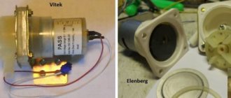
When the magnetic starter coil is pulled out from its place, the first step is to inspect its section (the frame on which the copper wire is wound) for cracks and chips. In our case, the copper wire is filled with plastic. If there is damage, the starter will make a lot of noise during operation. Then you need to pay attention to the coil itself. There should be no traces of heating (blackening) on the paper/plastic, and there should also be no burning smell. Typically, the main data is indicated on the side of the reels.
This is the number of turns, operating voltage, type of current (if alternating, then frequency). The brand and thickness of the wire and the brand of the starter for which it is intended are also indicated. Determining the presence of an interturn short circuit is quite difficult. For example, by abnormally low or high resistance. If the reel looks the same as in the photo above, then it can be rewound. If it is filled with plastic, it must be replaced.