Electromagnetic contactors (starters)
We need to bring some order to the terminology. Starters and contactors are often confused . To some they are the same thing, and some say that a contactor is just a big, powerful starter. But no one can really explain how powerful it is...
Previously, during the Soviet era, this was the case. Now starters that were produced or developed in those days are called starters (for example, PML, which is still produced in Ukraine), and new and foreign models are called contactors.
Electricians call the same devices starters, and sellers call them contactors. To be honest, I’m more used to talking about starters.
Necessary actions when operating contactors and magnetic starters
- Before installing the devices, it is necessary to remove grease from the working surfaces and check the condition of each electrical connection and check that the devices are adjusted correctly.
- It is necessary to regularly check the condition of the contact group, periodically inspecting it after 50,000 operations or after each power outage in emergency mode.
- When cleaning the surface of contacts, the main thing is to maintain their original shape.
- Check the location of the breaking contacts relative to each other. Copy paper will help.
- For contactors with several poles, the simultaneous closure of the contacts of all poles is checked.
- It is necessary to check the serviceability of the mechanical interlock.
- Constantly check the gap between the contacts. They are replaced when the original thickness is reduced by 50%, and for contacts with overlays by 80%.
Newly installed contacts must touch along a line whose total length is equal to 75% or more of the width of the moving contact. Contact displacement is allowed, no more than 1 mm in width.
What is the difference between a contactor and a starter?
In fact, a contactor is a device consisting only of an electromagnetic coil and contacts. When voltage is applied to the coil, the contacts close (or open). The contactor does not contain devices for protection, fixation, switching, indication, etc. A starter is a device that contains a contactor as the main component element. In addition, the starter usually contains a thermal relay for protection against overcurrent, START and STOP buttons, an indication, can be enclosed in a housing, and have a circuit breaker for short-circuit protection. In other words, the starter is used to start (turn on) various electricity consumers.
More details about the purpose and design of the contactor are described in the video:
Details on how a three-phase electric motor is connected to a starter and various circuits for connecting an electric motor are given in my article on connecting asynchronous motors. And another example of using starters is in the article about the hydraulic press circuit. Various schemes for switching on magnetic starters are discussed in detail here.
And if you are at all interested in what I write about, subscribe to receive new articles and join the group on VK!
The starter may contain two or three contactors. This happens in cases where reversible engine control , or during soft start , when a powerful engine is turned on first in a star circuit and then in a delta circuit.
Although such a scheme cannot be called “smooth”, there are special devices for smooth starting. Read my articles about the Soft Starter and about the Real Circuit for Switching on a Soft Starter.
Disassembled starter PML-1220 0*2B. The contactor and thermal relay are visible.
Officially, the differences between a contactor and a starter are specified in GOST R 50030.4.1-2012
(IEC 60947-4-1:2009) Low voltage distribution and control equipment. Part 4. Contactors and starters. Section 1. Electromechanical contactors and starters.
From this GOST we can conclude that the motor protection circuit breaker, star-delta circuit, soft starter and frequency converter are also starters!
More definitions of contactors and starters are given in GOST 17703-72 “Electrical switching devices. Basic concepts” and GOST R 500030.4.4-2012 “Low-voltage distribution and control equipment”.
It will also be interesting what huge debates flared up on my Yandex.Zen channel in an article about the differences between contactors and starters.
Distinctive features of contactors and magnetic starters
Contactors and magnetic starters are electrical devices that are important components of electrical networks. They are intended for communication between power-type circuits and control circuits. Often, equipment adjustment specialists cannot always give a substantiated answer as to how a contactor differs from a magnetic starter. Both perform a list of similar purposes, but still there are differences between them, since each of them has its own unique functions and features.
Differences between a relay and a contactor
Relays differ from contactors only in design and purpose, and the difference between them is sometimes barely distinguishable.
Usually,
- The relay does not have arc chutes.
- The relay is housed in a sealed housing.
- The relay is designed for low current and purely resistive loads.
- The relay has switching contacts, which means normally open and closed.
- The relay is not designed to connect a reactive three-phase load.
- A relay can have from 1 to 6 equivalent contacts, and a contactor must have 3 power and (as an option) 1-2 low-current contacts.
- The relay does not have additional functions or contacts, and the contactor can be supplemented with attachments for various installations and purposes.
- The relay is mounted on the panel and can be easily replaced using just your hands. In order to replace the contactor, you need to de-energize the equipment and use a screwdriver.
Learn more about what a relay is and what it is needed for in the video:
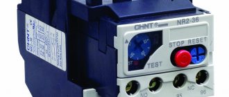
10.2. Electromagnetic current relays RTT5-16 for PM12 starters
The relay is designed to protect three-phase asynchronous electric motors with a squirrel-cage rotor from current overloads of unacceptable duration, including when one of the phases fails. The relay is attached directly to the PM12-016 starter or individually on a standard rail using a KP5 terminal block.
Specifications:
| Rated current, A | 16 |
| Rated current in auxiliary contacts, A | 6,3 |
| Power consumed by one current circuit, W | 2,1 |
| Response time, s: · from a cold state; from a heated state | 4—8 0,8 |
| Climatic performance | U |
| Accommodation category | 3 |
| Dimensions, mm | 44 x 55.5 x 88 |
| Weight, kg | 0,12 |
Characteristics and types of starters by characteristics
Before choosing a contactor, you need to decide on the load, and make the choice based primarily on the load power. The parameters of contactors can be clarified on the manufacturers’ websites or from trading organizations, but here we will present and consider the most important ones. The main parameters (current, load power) are usually indicated on the starter housing.
Size (conditional dimensions) of the starter (contactor)
The most important parameter, the value characterizes the power and dimensions of the starter. There are the following starter sizes:
- zero value – for a maximum current of up to 6 A (through each working contact)
- the first - for a maximum current of up to 9 - 18 A (depending on the design of the contacts)
- starter 2 sizes – up to 25 – 32 A
- starter 3 sizes – up to 40 – 50 A
- starter 4 sizes – up to 65 – 95 A
- 5th size starter – up to 100 – 160 A
- sixth value – from 160 A and above
This means the current for application category AC-3 (for an inductive load), for category AC-1 (resistive or low-inductive load - for example, heating elements) the maximum current for the same starter will be one and a half to two times higher. The size of the starter determines how much power it can switch (three-phase circuit 380 V, inductive load).
- 1 – up to 2.2 – 7.5 kW
- 2 – up to 11 – 15 kW
- 3 – up to 18 – 22 kW
- 4 – up to 30 – 45 kW
It must be said right away that this power is really the maximum; you really need to look at the current value of a particular starter (usually the second and third digits in the name). The size of the starter is indicated in the name by the first digit. When the current is exceeded or the current is close to the maximum, the number of operations (reliability) decreases sharply, so the starter must be selected with a power reserve.
Number of contacts (poles)
Contactors are mainly produced with three working contacts (for switching) and one additional one. An additional, or latching, contact is needed for interlocking, or “self-powering,” to lock the contactor in the on state when using the standard switching circuit. Additional contacts can be normally open (most often used) or normally closed.
To increase the number of additional contacts, contact attachments are used, the use of which significantly expands the range of circuit solutions. In the USSR, such additional consoles were called PKI, now there are other models on sale, but the essence is the same.
Additional contact attachments PKI, etc.
The maximum current of additional contacts, as a rule, is equal (in starters of the first and second values) or less than the maximum current of the main contacts. There are also additional contacts (attachments) of the PVL time delay, in which the contacts are turned on or off after a delay time. Read more in the article about pneumatic time delay relays.
Contactor coil voltage
Electromagnetic coils of contactors are usually available in the following voltages: 24, 36, 110, 230, 380 Volts. Larger starters use higher power coils. The coils are also sold separately, and it can be easily replaced in the contactor if a different voltage value is needed.
Contactor coils
As a rule, in the presence of a neutral conductor, it is advisable to use contactor coils for a voltage of 220 V, and in its absence (purely three-phase consumers) - coils for 380 V.
How to replace the contactor coil?
Sometimes a contactor with a coil of the required voltage is not available, so you don’t have to buy the entire contactor you need. Many manufacturers sell coils for different voltages and contactor sizes.
In particular, this applies to IEK, KEAZ. Foreign manufacturers, as a rule, make contactors non-separable, and do not sell coils for them separately.
It is worth saying that contactor coils for the required voltages should be included in repair kits, since this can be considered a consumable item. The main malfunctions of coils are winding breakage and housing deformation.
To increase the service life of contactor coils or electromagnets that remain on for a long time, it is permissible to operate them at a voltage of 85-90% of the nominal voltage.
Magnetic starters
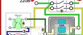
A magnetic starter is a low-voltage device of a combined type and electromagnetic principle, which starts electric motors, ensures their continuous rotation, disconnects them from the power supply, protects, and performs reversing functions.
Principle of operation
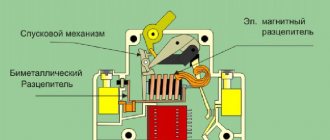
This device consists of a main part for stationary mounting, a coil, an armature that moves along the guides of the mechanism, a spring mechanism, stationary and moving contacts and a housing. The simplest starters appear in the form of a box equipped with a button and terminals for connection to power circuits and stationary contacts.
The principle of operation is that when current enters the starter coil, it is triggered according to the principle of an electromagnet. Under the influence of a magnetic field, the armature is attracted to the core, as a result of which the contact bridge closes and the electrical equipment starts up. The lower position of the armature affects the operation of the entire device. In this position, there must be reliable contact between the contacts, since this component plays the role of a strong connection of the input and output electrical wires at the moment the circuit operates.
The absence of current entails the disappearance of the magnetic field around the coil. This leads to the armature being thrown upward due to the energy of the springs; the contact bridge located on the moving part ensures a break in the power circuit, which leads to a shutdown of power and equipment. This system also has auxiliary block contacts.
The serviceability of magnetic starters can be checked manually. If the device is working properly, then when you press the anchor, you should feel resistance from the compression of the springs. This manual control is only valid for checks and is not used during the work process.
Application area
The main area of use of magnetic starters is starting, stopping and reversing asynchronous electric motors. And, since these devices are quite unpretentious and protected from environmental influences, they are installed for remote control of lighting equipment, compressor units, pumps, cranes, electric furnaces, conveyors, and air conditioners.
Types of starters by purpose
Now I will give a couple of examples of starters - real circuits.
Star-delta starter
This starter circuit is assembled on three second-value contactors and is used to connect an electric motor according to a star-delta circuit. At the top left three phases are supplied, at the bottom three phases go to power the motor. Red wires – powering the contactor coils and checking operation. Protection (automatic motor) is not shown.
reversing starter with automatic motor
Here is a reversing starter, with two mutually interlocked contactors. Automatic engine protection motor - on the right.
Main breakdowns of contactors and magnetic starters, and their causes
Control coil failure
- voltage was supplied from the electrical network that did not meet the recommendations. That is, a coil with a voltage of 220 volts was installed, and the voltage of the connected network was 380 volts;
- supplying current to the coil, at the contacts of which a jumper has formed. The result is a short circuit and burnt out coil contacts;
- interturn short circuit due to natural aging of insulation on the copper winding of the coil;
- exceeded operating temperatures.
Burnout of main contacts
- incorrect calculation of load parameters on the starter.
- connecting a device with two power and one additional contact to a three-phase load. The additional contact is not designed for a rated current higher than 10 A, as a result of which the weaker link burns out;
- low voltage on the coil, as a result of which there is a lack of power generated force necessary to engage the main contacts. The reason for this shortcoming lies in the different stiffness of the return springs, when chattering occurs and the constancy and contact area of the contacts decreases.
- During a long period of operation, due to the impact created by vibration, the fastening of the conductors with the contact terminals weakens. Reducing the area of contact closure entails local overheating, which disables the contacts.
Bonus
In conclusion, here are a few photographs of contactors that have served their time faithfully.
Starter 2 magnitude. Economic Council of the Latvian SSR, 1964
starter PME 211
PML starter, on the right is its Telemecanique prototype
It’s scary to watch, but these are exactly the kind of starters that were used in the USSR...
...and such. Doesn't it look a lot like a museum exhibit?
Where can you buy contactors now? Of course, in the nearby electrical store. And most importantly. Don't forget to tell the seller the coil voltage!
STRUCTURE OF THE CONVENTIONAL DESIGNATION OF PML STARTERS - X1 X2 X3 X4 X5 X6 X7 X8 X9 X1 - A number indicating the design of the starters according to their purpose and the presence of a thermal relay:
- 1- 10A, 16A
- 2 - 25A
- 3 - 40A
- 4 - 63A, 80A
- 5 - 100A, 125A
- 6 - 160A
- 7 - 250A
- 8 - 400A
- 9 - 500A
X2 - A number indicating the design of the starters according to their purpose and the presence of a thermal relay:
- 1 - irreversible starter without thermal relay
- 2 - irreversible starter with thermal relay
- 5 - reversing starter without thermal relay with mechanical interlocking for degree of protection IP00, IP20 and with electrical and mechanical interlocking for degree of protection IP40, IP54
- 6 - reversing starter with thermal relay with electrical and mechanical interlocks
- 7 - star-delta starter
X3 - A number indicating the design of the starters according to the degree of protection and the presence of buttons:
- 0 — degree of protection IP00
- 1 - degree of protection IP54 without buttons (for starters without a thermal relay) or with a “Relay” button (for starters with a thermal relay)
- 2 – degree of protection IP54 with “Start” and “Stop” buttons
- 3 — degree of protection IP54 with “Start” and “Stop” buttons and a signal lamp (manufactured only for voltage 127, 220, 380V, 50Hz)
- 4 - degree of protection IP40 without buttons
- 6 — degree of protection IP20
X4 - A number indicating the type of starter based on the number and type of auxiliary circuit contacts
Number Type of control circuit current Number and design of contacts of the auxiliary circuit of starters at 10-16-25A, 40A (with reduced ratings) Starters for 40-63-80A Starters for 100, 125, 160, 250, 400A 0 variable 1z 1z+1r 1z+1r 1 variable 1r — 2z+2r 2 variable — — 3z+3r 3 variable — — 3z+1r 4 variable — — 5z+1r 5 constant 1z — — 6 constant 1r — —
X5 —
- D - Letter designating starters with a rated current of 16A - for 1 - value;
- 80A - for 4th value;
- with reduced weight and dimensions - for size 3;
- 100A - for the 5th value.
X6 - M - Letter designating the design of starters with the possibility of mounting both on a standard rail and with screws on a plane. X7 - Letter characterizing the climatic version according to GOST 15150-69 (0.0*; Ohm). X8 - A figure characterizing the placement category according to GOST 15150-69 (2.4). X9 - Letter indicating wear resistance design (A, B, C), million cycles. Note:
- The following contact designation is accepted: z - normally open (NO), p - normally closed (NC).
- When using PKL and PKB attachments, you can get a different number of auxiliary circuit contacts.
- The specified number of auxiliary circuit contacts is installed on each contactor of the reversing starter.
- The presence of adapter panels allows you to install starters of the PML series instead of the PMA, PME, PM series, etc. (See “ Replacement table ”)
Switching wear resistance of contacts of the auxiliary circuit for wear resistance versions of starters A, B, C with an inductive load with a power factor of (0.7 ± 0.5) when turned on, and (0.5 ± 0.05) when turning off alternating current and constant power no more than 0.05 s at constant current must correspond to the data specified in the table. Note: IP00 - version without shell. IP20 - version without shell. IP40 - enclosed version. IP54 - enclosed version.
| Switched current, A | Switched current, A | Electrical wear resistance, total. resource, million cycles | ||||
| variable | constant | variable | constant | |||
| at voltage, V | ||||||
| 380 | 220 | 380 | 220 | A | B | IN |
| 7,80 | 0,15 | 0,78 | 0,15 | 3,00 | 1,50 | 0,20 |
| 13,80 | 0,30 | 1,36 | 0,30 | 1,00 | 0,50 | 0,10 |
Selection table for electromagnetic starters of the PML series
| Type | Degree of protection | Characteristics | Rec. contact | Weight, kg | Engine power for category AC-3; kW | Switching wear resistance, million cycles | ||||
| 220V | 380V | 500V | A | B | IN | |||||
| Electromagnetic starters PML for current 10A | ||||||||||
| PML 1100 | IP00 | open | +1z | 0,32 | 2,2 | 4,0 | 5,5 | 3,0 | 1,50 | 0,30 |
| PML 1101 | IP00 | open | +1r | |||||||
| PML 1160M | IP20 | DIN rail | +1z | |||||||
| PML 1161M | IP20 | DIN rail | +1r | |||||||
| PML 1140 | IP40 | shell | — | 0,75 | 3,0 | 5,5 | 7,5 | — | ||
| PML 1110 | IP54 | shell | — | |||||||
| PML 1210 | IP54 | relay, shell, button, “Stop” | +1z | 1,04 | ||||||
| PML 1220 | IP54 | relay, shell, button, “Stop”, “Start” | +1z | |||||||
| PML 1230 | IP54 | relay, shell, button, “Stop”, “Start”, signal. Lamp | +1z | 1,13 | ||||||
| PML 1501 | IP00 | reverse, open | +2р | 0,68 | 3,0 | |||||
| PML 1561M | IP20 | reverse, DIN rail | +2р | |||||||
| PML 1541 | IP40 | reverse, shell | +2р | 2,00 | — | |||||
| PML 1511 | IP54 | reverse, shell | +2р | |||||||
| PML 1611 | IP54 | reverse, relay, shell, button, “Stop” | +2z+1z | 2,15 | ||||||
| PML 1621 | IP54 | reverse, relay, shell, button, “Stop”, “Start” | +2z+1z | 2,23 | ||||||
| PML 1631 | IP54 | reverse, relay, shell, button, “Stop”, “Start”, signal. Lamp | +2z+1z | 2,27 | ||||||
| PML 1720 | IP54 | star-delta, relay, shell, button, “Stop”, “Start” | +1р+2з | 3,30 | 5,5 | 11,0 | — | |||
| Electromagnetic starters PML for current 16A | ||||||||||
| PML 1160DM | IP20 | DIN rail | +1z | 0,34 | 4,0 | 7,5 | 10,0 | 2,0 | 1,00 | 0,30 |
| PML 1161DM | IP20 | DIN rail | +1r | |||||||
| PML 1210D | IP54 | relay, shell, button, “Stop” | +1z | 1,20 | — | |||||
| PML 1220D | IP54 | relay, shell, button, “Stop”, “Start” | +1z | |||||||
| PML 1230D | IP54 | relay, shell, button, “Stop”, “Start”, signal. Lamp | +1z | 1,29 | ||||||
| PML 1561DM | IP20 | reverse, DIN rail | +2р | 0,72 | 3,0 | |||||
| PML 1611D | IP54 | reverse, relay, shell, button, “Stop” | +2z+1z | 2,77 | ||||||
| PML 1621D | IP54 | reverse, relay, shell, button, “Stop”, “Start” | +2z+1z | 2,86 | — | |||||
| PML 1631D | IP54 | reverse, relay, shell, button, “Stop”, “Start”, signal. Lamp | +2z+1z | |||||||
| Electromagnetic starters PML for current 25A | ||||||||||
| PML 2100 | IP00 | open | +1z | 0,53 | 5,5 | 11,0 | 15,0 | 2,0 | 1,00 | 0,30 |
| PML 2101 | IP00 | open | +1r | |||||||
| PML 2160M | IP20 | DIN rail | +1z | |||||||
| PML 2161M | IP20 | DIN rail | +1r | |||||||
| PML 2140 | IP40 | shell | — | 1,06 | — | |||||
| PML 2110 | IP54 | shell | — | 1,07 | ||||||
| PML 2210 | IP54 | relay, shell, button, “Stop” | +1z | 1,20 | ||||||
| PML 2220 | IP54 | relay, shell, button, “Stop”, “Start” | +1z | |||||||
| PML 2230 | IP54 | relay, shell, button, “Stop”, “Start”, signal. lamp | +1z | 1,29 | ||||||
| PML 2501 | IP00 | reverse, open | +2р | 1,14 | 2,0 | |||||
| PML 2561M | IP20 | reverse, DIN rail | +2р | 1,21 | ||||||
| PML 2541 | IP40 | reverse, shell | +2р | 2,47 | — | |||||
| PML 2511 | IP54 | reverse, shell | +2р | 2,70 | ||||||
| PML 2611 | IP54 | reverse, relay, shell, button, “Stop” | +2z+1z | 2,77 | ||||||
| PML 2621 | IP54 | reverse, relay, shell, button, “Stop”, “Start” | +2z+1z | 2,77 | ||||||
| PML 2631 | IP54 | reverse, relay, shell, button, “Stop”, “Start”, signal. lamp | +2z+1z | 2,86 | ||||||
| PML 2720 | IP54 | star-delta, relay, shell, button, “Stop”, “Start” | +1р+2з | 5,0 | 11,0 | 22,0 | — | |||
| Electromagnetic starters PML for current 40A | ||||||||||
| PML 3100 | IP00 | open | +1р+1з | 1,22 | 11,0 | 18,5 | 25,0 | 2,0 | 1,00 | 0,30 |
| PML 3160M | IP20 | DIN rail | +1р+1з | 1,34 | ||||||
| PML 3140 | IP54 | shell | +1r | 2,74 | 22,0 | — | ||||
| PML 3110 | IP54 | shell | +1r | 2,80 | ||||||
| PML 3210 | IP54 | relay, shell, button, “Stop” | +1р+1з | 3,10 | ||||||
| PML 3220 | IP54 | relay, shell, button, “Stop”, “Start” | +1р+1з | 3,13 | ||||||
| PML 3230 | IP54 | relay, shell, button, “Stop”, “Start”, signal. lamp | +1р+1з | 3,16 | ||||||
| PML 3500 | IP00 | reverse, open | +2р+2з | 2,85 | 25,0 | 2,0 | ||||
| PML 3560M | IP20 | reverse, DIN rail | +2р+2з | 2,88 | ||||||
| PML 3540 | IP54 | reverse, shell | — | 5,69 | 22,0 | — | ||||
| PML 3510 | IP54 | reverse, shell | — | 5,70 | ||||||
| PML 3610 | IP54 | reverse, relay, shell, button, “Stop” | +1z | 6,00 | ||||||
| PML 3620 | IP54 | reverse, relay, shell, button, “Stop”, “Start” | +1z | 6,08 | ||||||
| PML 3630 | IP54 | reverse, relay, shell, button, “Stop”, “Start”, signal. lamp | +1z | 6,12 | ||||||
| PML 3720 | IP54 | star-delta, relay, shell, button, “Stop”, “Start” | +1р+3з | 8,70 | 18,5 | 37,0 | — | |||
| Electromagnetic starters PML for current 40A small-sized | ||||||||||
| PML 3160DM | IP20 | DIN rail | +1z | 0,60 | 11,0 | 18,5 | 25,0 | 2,0 | 1,00 | 0,30 |
| PML 3161DM | IP20 | DIN rail | +1r | |||||||
| PML 3210D | IP54 | relay, shell, button, “Stop” | +1z | 2,40 | 22,0 | — | ||||
| PML 3220D | IP54 | relay, shell, button, “Stop”, “Start” | +1z | |||||||
| PML 3230D | IP54 | relay, shell, button, “Stop”, “Start”, signal. lamp | +1z | 2,42 | ||||||
| PML 3561DM | IP20 | reverse, DIN rail | +2р | 2,44 | 25,0 | 2,0 | ||||
| PML 3611D | IP54 | reverse, relay, shell, button, “Stop” | +2р+1з | 1,33 | 22,0 | — | ||||
| PML 3621D | IP54 | reverse, relay, shell, button, “Stop”, “Start” | +2р+1з | 3,24 | ||||||
| PML 3631D | IP54 | reverse, relay, shell, button, “Stop”, “Start”, signal. lamp | +2р+1з | 3,30 | ||||||
| Electromagnetic starters PML for current 63A | ||||||||||
| PML 4100 | IP00 | open | +1р+1з | 1,28 | 18,5 | 30,0 | 40,0 | 2,0 | 1,00 | 0,30 |
| PML 4160M | IP20 | DIN rail | +1р+1з | 1,34 | ||||||
| PML 4140 | IP40 | shell | +1r | 2,80 | 37,0 | — | ||||
| PML 4110 | IP54 | shell | +1r | 2,81 | ||||||
| PML 4210 | IP54 | relay, shell, button, “Stop” | +1р+1з | 3,11 | ||||||
| PML 4220 | IP54 | relay, shell, button, “Stop”, “Start” | +1р+1з | 3,14 | ||||||
| PML 4230 | IP54 | relay, shell, button, “Stop”, “Start”, signal. lamp | +1р+1з | 3,16 | ||||||
| PML 4500 | IP00 | reverse, open | +2р+2з | 2,85 | 40,0 | 2,0 | ||||
| PML 4560M | IP20 | reverse, DIN rail | +2р+2з | 2,88 | ||||||
| PML 4540 | IP40 | reverse, shell | — | 5,69 | 37,0 | — | ||||
| PML 4510 | IP54 | reverse, shell | — | 5,70 | ||||||
| PML 4610 | IP54 | reverse, relay, shell, button, “Stop” | +1z | 6,00 | ||||||
| PML 4620 | IP54 | reverse, relay, shell, button, “Stop”, “Start” | +1z | 6,08 | ||||||
| PML 4630 | IP54 | reverse, relay, shell, button, “Stop”, “Start”, signal. lamp | +1z | 6,12 | ||||||
| PML 4720 | IP54 | star-delta, relay, shell, button, “Stop”, “Start” | +1р+3з | 8,70 | 33,0 | 59,0 | — | |||
| Electromagnetic starters PML for current 80A | ||||||||||
| PML 4160DM | IP20 | DIN rail | +1р+1з | 1,44 | 22,0 | 40,0 | 55,0 | 1,5 | 0,75 | 0,30 |
| PML 4560DM | IP20 | reverse, DIN rail | +2р+2з | 3,00 | ||||||
| Electromagnetic starters PML for current 125A | ||||||||||
| PML 5100 | IP00 | open | +1р+1з | 4,60 | — | 55,0 | — | — | 0,75 | — |
| PML 5101 | IP00 | +2р+2з | ||||||||
| PML 5103 | IP00 | +1р+3з | ||||||||
| PML 5102 | IP00 | +3р+3з | ||||||||
| PML 5104 | IP00 | +1р+5з | ||||||||
| PML 5110 | IP54 | shell | +1р+1з | 14,90 | ||||||
| PML 5111 | IP54 | +2р+2з | ||||||||
| PML 5113 | IP54 | +1р+3з | ||||||||
| PML 5112 | IP54 | +3р+3з | ||||||||
| PML 5114 | IP54 | +1р+5з | ||||||||
| PML 5210 | IP54 | relay, shell, button, “Stop” | +1р+1з | 16,70 | ||||||
| PML 5211 | IP54 | +2р+2з | ||||||||
| PML 5213 | IP54 | +1р+3з | ||||||||
| PML 5212 | IP54 | +3р+3з | ||||||||
| PML 5214 | IP54 | +1р+5з | ||||||||
| PML 5500 | IP00 | reverse | +2р+2з | 9,80 | ||||||
| PML 5501 | IP00 | +4р+4з | ||||||||
| PML 5503 | IP00 | +2р+6з | ||||||||
| PML 5502 | IP00 | +6р+6з | ||||||||
| PML 5504 | IP00 | +2р+10з | ||||||||
| PML 5510 | IP54 | reverse, shell | +2р+2з | 23,10 | ||||||
| PML 5511 | IP54 | +4р+4з | ||||||||
| PML 5513 | IP54 | +2р+6з | ||||||||
| PML 5512 | IP54 | +6р+6з | ||||||||
| PML 5514 | IP54 | +2р+10з | ||||||||
| PML 5610 | IP54 | reverse, relay, shell, button, “Stop” | +2р+2з | 24,90 | ||||||
| PML 5611 | IP54 | +4р+4з | ||||||||
| PML 5613 | IP54 | +2р+6з | ||||||||
| PML 5612 | IP54 | +6р+6з | ||||||||
| PML 5614 | IP54 | +2р+10з | ||||||||
| Electromagnetic starters PML for current 160A | ||||||||||
| PML 6110 | IP00 | open | +1р+1з | 4,70 | — | 75,0 | — | — | 0,75 | — |
| PML 6101 | IP00 | +2р+2з | ||||||||
| PML 6103 | IP00 | +1р+3з | ||||||||
| PML 6102 | IP00 | +3р+3з | ||||||||
| PML 6104 | IP00 | +1р+5з | ||||||||
| PML 6110 | IP54 | shell | +1р+1з | 15,00 | ||||||
| PML 6111 | IP54 | +2р+2з | ||||||||
| PML 6113 | IP54 | +1р+3з | ||||||||
| PML 6112 | IP54 | +3р+3з | ||||||||
| PML 6114 | IP54 | +1р+5з | ||||||||
| PML 6210 | IP54 | relay, shell, button, “Stop” | +1р+1з | 16,80 | ||||||
| PML 6211 | IP54 | +2р+2з | ||||||||
| PML 6213 | IP54 | +1р+3з | ||||||||
| PML 6212 | IP54 | +3р+3з | ||||||||
| PML 6214 | IP54 | +1р+5з | ||||||||
| PML 6500 | IP00 | reverse | +2р+2з | 10,00 | ||||||
| PML 6501 | IP00 | +4р+4з | ||||||||
| PML 6503 | IP00 | +2р+6з | ||||||||
| PML 6502 | IP00 | +6р+6з | ||||||||
| PML 6504 | IP00 | +2р+10з | ||||||||
| PML 6510 | IP54 | reverse, shell | +2р+2з | 23,30 | ||||||
| PML 6511 | IP54 | +4р+4з | ||||||||
| PML 6513 | IP54 | +2р+6з | ||||||||
| PML 6512 | IP54 | +6р+6з | ||||||||
| PML 6514 | IP54 | +2р+10з | ||||||||
| PML 6610 | IP54 | reverse, relay, shell, button, “Stop” | +2р+2з | 25,10 | ||||||
| PML 6611 | IP54 | +4р+4з | ||||||||
| PML 6613 | IP54 | +2р+6з | ||||||||
| PML 6612 | IP54 | +6р+6з | ||||||||
| PML 6614 | IP54 | +2р+10з | ||||||||
| Electromagnetic starters PML for current 250A | ||||||||||
| PML 7100 | IP00 | open | +1р+1з | 6,60 | — | 132,0 | — | — | 0,50 | — |
| PML 7101 | IP00 | +2р+2з | ||||||||
| PML 7103 | IP00 | +1р+3з | ||||||||
| PML 7102 | IP00 | +3р+3з | ||||||||
| PML 7104 | IP00 | +1р+5з | ||||||||
| PML 7110 | IP54 | shell | +1р+1з | 17,85 | ||||||
| PML 7111 | IP54 | +2р+2з | ||||||||
| PML 7113 | IP54 | +1р+3з | ||||||||
| PML 7112 | IP54 | +3р+3з | ||||||||
| PML 7114 | IP54 | +1р+5з | ||||||||
| PML 7210 | IP54 | relay, shell, button, “Stop” | +1р+1з | 19,80 | ||||||
| PML 7211 | IP54 | +2р+2з | ||||||||
| PML 7213 | IP54 | +1р+3з | ||||||||
| PML 7212 | IP54 | +3р+3з | ||||||||
| PML 7214 | IP54 | +1р+5з | ||||||||
| PML 7500 | IP00 | reverse | +2р+2з | 14,30 | ||||||
| PML 7501 | IP00 | +4р+4з | ||||||||
| PML 7503 | IP00 | +2р+6з | ||||||||
| PML 7502 | IP00 | +6р+6з | ||||||||
| PML 7504 | IP00 | +2р+10з | ||||||||
| PML 7510 | IP54 | reverse, shell | +2р+2з | 32,20 | ||||||
| PML 7511 | IP54 | +4р+4з | ||||||||
| PML 7513 | IP54 | +2р+6з | ||||||||
| PML 7512 | IP54 | +6р+6з | ||||||||
| PML 7514 | IP54 | +2р+10з | ||||||||
| PML 7610 | IP54 | reverse, relay, shell, button, “Stop” | +2р+2з | 34,20 | ||||||
| PML 7611 | IP54 | +4р+4з | ||||||||
| PML 7613 | IP54 | +2р+6з | ||||||||
| PML 7612 | IP54 | +6р+6з | ||||||||
| PML 7614 | IP54 | +2р+10з | ||||||||
| Electromagnetic starters PML for current 400A | ||||||||||
| PML 8100 | IP00 | open | +1р+1з | 8,00 | — | 200,0 | — | — | — | 0,25 |
| PML 8101 | IP00 | +2р+2з | ||||||||
| PML 8103 | IP00 | +1р+3з | ||||||||
| PML 8102 | IP00 | +3р+3з | ||||||||
| PML 8104 | IP00 | +1р+5з | ||||||||
| PML 8500 | IP00 | reverse, open | +2р+2з | 19,00 | ||||||
| PML 8501 | IP00 | +4р+4з | ||||||||
| PML 8503 | IP00 | +2р+6з | ||||||||
| PML 8502 | IP00 | +6р+6з | ||||||||
| PML 8504 | IP00 | +2р+10з | ||||||||
| Electromagnetic starters PML for current 500A | ||||||||||
| PML 9100 | IP00 | open | +1р+1з | 8,00 | — | 250,0 | — | — | — | 0,25 |
| PML 9101 | IP00 | +2р+2з | ||||||||
| PML 9103 | IP00 | +1р+3з | ||||||||
| PML 9102 | IP00 | +3р+3з | ||||||||
| PML 9104 | IP00 | +1р+5з | ||||||||
| PML 9500 | IP00 | reverse, open | +2р+2з | 19,00 | ||||||
| PML 9501 | IP00 | +4р+4з | ||||||||
| PML 9503 | IP00 | +2р+6з | ||||||||
| PML 9502 | IP00 | +6р+6з | ||||||||
| PML 9504 | IP00 | +2р+10з | ||||||||
| Electromagnetic starters PML with direct current control | ||||||||||
| PML 1165M | IP20 | open, 10A | +1z | |||||||
| PML 1166M | IP20 | open, 10A | +1r | |||||||
| PML 1566M | IP20 | open, reversible, 10A | +1z+1r | |||||||
| PML 2165M | IP20 | open, 25A | +1z | |||||||
| PML 2166M | IP20 | open, 25A | +1r | |||||||
| PML 2565m | IP20 | open, reversible, 25A | +1z | |||||||
| PML 2566M | IP20 | open, reversible, 25A | +1r | |||||||