What color are plus and minus?
Author Mashka asked a question in the Technology
, what color is the plus and minus wire? The charger has 2 wires, black and white. where is the plus where is the minus? and got the best answer
Answer from Yes, it's me! [guru] Minus - black, as a rule.
The most important responsibility during the flight is to provide more details.
Correct identification of conductors is needed to solve various practical problems. If you correctly determine the “red black plus minus” correspondence, the normal functioning of the audio speakers will be ensured. Errors in power networks when determining “phase” and “zero” are accompanied by significant damage and emergency situations. The information presented below will help eliminate incorrect actions during installation work.
Black, white, red - all of them are dangerous
Black and white, as well as the red wire, in electrical engineering indicate a phase conductor. This variety is stipulated by GOST and implies that in different circuits preference will be given to one of these colors.
- Black color is used in AC and DC power circuits.
- Red color is used in AC control circuits.
- Orange is found in interlock control circuits powered by an external power source.
Working with electricity requires care
For example, in an AC circuit, the black color of the wire indicates “minus”, and the red insulation indicates “plus”. Three-phase transformer networks with five cores require three different colors for each phase:
- yellow tint for phase A;
- green wire for phase B;
- The C-phase is indicated by a red wire.
For 380 V cables, the three phases correspond to other wire colors: white - A, black - B, red - C.
We must not forget that standards change from time to time, and white is one of the most common colors for electrical cable insulation. It is possible that an unscrupulous electrician could install the wiring from two white wires, forgetting to indicate the markings.
To find out the location of the phase, you will have to use an indicator screwdriver. The following information may be helpful.
Until 2000, the following color markings were found:
- white color – N-conductor;
- black – PE;
- another bright shade is phase.
Wire Classification Options
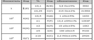
The typical cable name contains letters and numbers. By decoding these symbols you can find out the main characteristics of products in this category:
- conductor (shell) materials;
- number of cores;
- cross-sectional area;
- Extra options.
Example of decoding (AVBbv-ng):
- A – the core is made of aluminum (copper is not marked);
- B – insulating shells are made of PVC;
- BB – protection against mechanical damage, made of steel tape without a damping gasket;
- ng – components that prevent combustion have been added to the polymer shell.
Pink wire
A set of wires for a car radio may contain a cable covered with a pink protective layer. The element is used on head units capable of playing video. Used to switch an external rear view camera, providing signal broadcast. When using this type of equipment, signal compatibility must be ensured, otherwise the display image will be upside down.
To provide power to the camera, a Reverse wire is used, which allows you to enable signal transmission when using reverse gear. The cord is connected to the power supply circuits for the reversing lamps. When using standard parking sensors, it is possible to connect the cable to the controller connector.
An additional harness can be used in the design of the head unit to reduce the sound volume when reverse gear is engaged. The same cable, covered with a yellow-black insulator, is responsible for turning off the broadcast when a phone call arrives. If the car is not equipped with a cell phone connection unit, the cord is not used.
The harness also includes 8 cables intended for connecting rear and front speakers. When using component acoustics, it is necessary to connect the elements to a common channel, while controlling the resistance and power. All negative outputs from the speaker coils must be fed to the appropriate connectors on the amplifier.
It is not allowed to combine the poles into a single line and short circuit the nodes to the car body.
To install the low-frequency speakers, a separate wire is used, laid independently. On some cars, the subwoofer is a standard device, located in the niche for the spare wheel or the internal cavity of its disk. Separate cables are used for switching; the color of the insulation depends on the vehicle model.
On standard radios there is a flat cable designed to transmit information to the display, located in a separate pocket on the instrument panel. The harness consists of a large number of wires covered with white and gray insulation. The protective layer ensures the solidity of the product. The cable is secured with special clamps that ensure reliable contact and protection from moisture.
Some Pioneer head units have an additional cable designed to connect a security system. The cord is connected to the plug, the commutation point is designated Alarm. Using a digital CAN or K-Line bus on a car requires connecting the radio to the circuit. For this purpose, separate cords are used, connected to a common connection connector.
Marking of wires for alternating three-phase current
The special color designation of the shell helps to determine the purpose of individual lines even without studying the accompanying design documentation:
- gray, purple, orange or red wire – phase;
- yellow and green stripes – grounding;
- blue or a combination of white and blue stripes is neutral.
Such designations simplify installation operations when laying power lines during the assembly of electrical panels. It is especially important to eliminate errors when hidden installation of communications inside building structures is used. In this case, correcting incorrect actions will be accompanied by increased costs.
Marking and color coding of wires
Let's look at the color code for car radio wires:
- Black (indicated by GROUND or GND) is the negative of the battery;
- Red (ACC or A+ marking) is the plus of the ignition switch;
- Yellow (indicated by BAT or B+) is the positive from the battery;
- White with a stripe (marked FL-) is the minus of the front left speaker;
- White without a stripe (indicated by FL+) is a plus of the front left speaker;
- Gray with a stripe (marked FR-) is the minus of the right front speaker;
- Gray without a stripe (indicated by FR+) is a plus for the right front speaker;
- Green with a stripe (marked RL-) is the minus of the left rear speaker;
- Green without a stripe (designation RL+) is a plus for the left rear speaker;
- Purple with a stripe (marked RR-) is the minus of the right rear speaker;
- Purple without a stripe (designation RR+) is a plus for the right rear speaker.
Color of wires plus (+) and minus (-) in DC networks
Is the red wire positive or negative? Such questions arise when working with DC electrical circuits.
Red
To remember which plus is red or black, they use the name of a well-known international organization - the Red Cross. This phrase suggests that red means plus.
Black
Black color indicates the negative conductor. These markings can be seen on typical household equipment:
- power supplies;
- audio, video equipment;
- other devices with electronic software control units.
Plus
The polarity of conductors must be observed when repairing standard electrical equipment of cars. In some situations, confusion with plus and minus is accompanied by a violation of the functional state.
Minus
The high power of connected consumers increases the responsibility for performing repair and adjustment work. In such situations, it is necessary to eliminate errors in determining polarity. Strong direct current is used to supply electricity:
- warehouse and municipal transport;
- lifting mechanisms;
- sensors and automation.
Blue wire
The blue wire provides a control signal to the antenna amplifier or electric drive, which extends the signal receiver pin out of the wing cavity. If the car is not equipped with such equipment, the cable is carefully twisted and insulated. The colors of the wires located on the antenna electric drive unit depend on the vehicle modification.
Blue insulation is also used to protect the cord, which is needed to control an external amplifier. A similar color scheme is used on Sony head units. When the player is activated, a control pulse is sent through the “remote” cable, which ensures the start of operation of the external amplifier and acoustics. After the engine is turned off and the radio stops working, the amplifier is automatically de-energized, ensuring that the vehicle’s battery remains charged.
Blue-white wire
Blue and white insulation colors are used to mark cables used to control low-current external equipment. A positive signal appears on the cable only after the head speaker is turned on. The permissible current transmitted through the cord does not exceed 200 mA. Under increased load, overheating and irreversible destruction of the electronic controllers located inside the player occurs. If the user intends to switch powerful equipment, then it is necessary to introduce a unloading relay into the circuit.
Wire colors in electrical wiring
The color identification scheme is convenient not only for installation. As a rule, different contractors install and operate electrical wiring. Compliance with standards prevents errors during repair work and in the modernization process.
Something to remember! Domestic standards have changed several times over the past decades. Currently, the markings discussed above are used.
Color of zero working and zero protective wires
The color options for the shells will help you recognize the intended purpose of the conductors:
- blue – working zero;
- transverse or longitudinal combinations of yellow and green stripes - protective zero;
- main blue with a change to a combination of yellow and green stripes at the junctions - combined working and protective zero.
For your information. The last universal option can be done in the reverse way. The main part of the line is created from a combination of yellow and green stripes, with blue color applied at the junctions.
How to read car electrical diagrams?
In order to understand the contents of the circuit, you need to know the correspondence between the circuit symbols and the real elements of the device. What functions do these devices perform and how do they interact with each other?
Let's define the terms:
- A circuit element is a component of a circuit that performs a specific function in a product and cannot be divided into parts that have an independent purpose.
- A device is a collection of elements representing a single structure (block, board, etc.).
- Schematic diagram (complete) - a diagram that defines the complete composition of elements and connections between them, and, as a rule, gives a detailed understanding of the principles of operation of the product. Schematic diagrams are used to study the principles of operation of products, as well as for their adjustment, control and repair. They serve as the basis for the development of other design documents, for example, connection diagrams (installation diagrams) and drawings.
- Connection diagram (installation) - a diagram showing the connections of the component parts of the product and defining the wires, harnesses, cables that make these connections, as well as the places of their connections and input (connectors, boards, etc.).
- Layout diagram - a diagram that determines the relative location of the component parts of the product, and, if necessary, also harnesses, wires, cables, etc.
- A harness is a set of wires packaged in a certain way into a single whole.
In the electrical equipment diagrams of cars, the schematic, installation, and layout diagrams are combined into one in a simplified form; the simplification concerns the wiring and layout diagrams. In the diagrams, the devices have a design that to some extent corresponds to their appearance, and they are located according to the diagram in the same way (top view) as in reality physically, with a certain simplification. This combination applies mainly to the circuits of cars of early releases. The circuits of modern cars are designed differently, due to the significant complexity of electrical equipment, the layout is carried out separately.
When reading diagrams, you need to know the fundamental principles:
- All connection wires are color coded, which can consist of one color or two (main and additional). Transverse or longitudinal strokes are applied with additional color.
- Within one harness, wires of the same marking have a galvanic connection (physically connected to each other).
- In the diagrams, the wire at the entrance to the harness is inclined in the direction where it is laid.
- Black color, as a rule, indicates a wire that is connected to the car body (ground).
- The positions of the relay contacts are indicated in the state when no current flows through their winding. According to the initial state, the relay contacts differ - normally closed and normally open.
- Some wires have a digital designation at the point of connection to the device, which allows you to determine where it comes from without tracing the circuit. See table.
According to DIN 72552 (commonly used values):
| Contact | Meaning |
| 15 | Battery positive after the ignition key contacts. |
| 30 | Plus the battery directly. |
| 31 | Minus the battery directly or the housing. |
| 50 | Starter control. |
| 53 | Wiper. |
| 56 | Headlight. |
| 56a | High beam. |
| 56b | Low beam. |
| 58 | Parking lights. |
| 85 | Relay winding (-). |
| 86 | Relay coil (+). |
| 87 | Common relay contact). |
| 87a | Normally closed relay contact. |
| 87b | Normally open relay contact. |
| 88 | Common contact 2 relays. |
| 88a | Normally closed relay contact 2. |
| 88b | Normally open relay contact 2. |
List of the most used symbolic drawings:
Also often with a circuit element there is a symbolic drawing explaining which device this element belongs to.
- Alarm.
- Battery.
- Fan.
- Air damper.
- Oil pressure.
- High beam
- Pad wear sensor.
- Egnition lock.
- Sound signal.
- Turn indicator.
- Outdoor Lighting.
- Heated rear window.
- Windshield washer.
- Rear window washer.
- Headlight washer.
- Interior lighting.
- Windshield cleaner.
- Rear window cleaner.
- Headlight cleaner.
- Cigarette lighter.
- Anti-fog equipment.
- Instrument lighting brightness control.
- Reversing light.
- Glass door lifts
- Coolant temperature.
- Brakes.
- Fuel level and reserve indicator.
- Washer fluid level.
- Coolant level.
Designations of circuit elements.
- Switch.
- Diode.
- Lamp with two filaments.
- Lamp.
- Variable resistor.
- Fuse.
- Resistor.
- Relay.
- Zener diode.
- 1.Off (contacts 1 and 6 are closed);
- 2. Switched on “slowly” (contacts 2 and 4, as well as 5 and 6 are closed);
- 3. “Fast” switched on (contacts 3 and 4 are closed).
» /> Three lever switch. This switch consists of several types of contacts. Non-fixed ones are contacts for turning on the washer, a sound signal and a short-term high beam signal (contacts 2 and 6 are closed), fixed ones are low beam (contacts 4 and 5 are closed), high beam (contacts 2 and 5 are closed), turning on the turn signal and turning on the windshield wiper which has 3 modes:
- 1.Off (contacts 1 and 6 are closed);
- 2. Switched on “slowly” (contacts 2 and 4, as well as 5 and 6 are closed);
- 3. “Fast” switched on (contacts 3 and 4 are closed).
How to read electrical circuit diagrams of foreign cars?
Let's look at an example of reading Nissan car diagrams. To do this, we need to familiarize ourselves with the designation system for elements of electrical equipment on the diagrams. Let's start with the designation of connector contacts. As shown in Fig.1.
Next to the connector picture there is a designation on which side of the connector it is viewed from, the contact side (Terminal Side) (TS) or the harness side (Harness Side) (HS). Please note that the connector outline, where the contacts are viewed from the wire side, is outlined with a line.
Figure 2 and Figure 3 show the designations of the circuit elements, the meaning of which is explained in Table 1.
| Number | Name | Description |
| 1 | Battery | Battery |
| 2 | Fusible link | Fuse installed in the wire |
| 3 | Number fusible link or fuse | Serial number of fused line or fuse |
| 4 | Fuse | Fuse |
| 5 | Current rating | Fuse rating in amperes |
| 6 | Optional splice | The circle indicates that the connection depends on the vehicle version |
| 7 | Connector number | Connector number |
| 8 | Splice | The black circle indicates the connection of conductors |
| 9 | Page crossing | This chain continues on the next page |
| 10 | Option abbreviation | The chain between these marks is present only for all-wheel drive |
| 11 | Relay | Shows internal relay connections |
| 12 | Option description | Shows a variant of the circuit depending on the vehicle |
| 13 | Switch | State of contacts depending on switch position (closed or open) |
| 14 | Circuit | Chain |
| 15 | System branch | Indicates that the connection is going to another system (head lighting) |
| 16 | Shielded line | The line is shielded |
| 17 | Component name | Schematic element name |
| 18 | Ground(GND) | Grounding |
| 19 | Connector | The numbering order of the contacts when viewed from the harness side is indicated. |
| 20 | Connectors | Indicates that the wire has 2 connectors |
| 21 | Wire color | Abbreviation for wire color |
| 22 | Terminal number | Describes the pin number, wire color and signal name |
Table 1.
Color abbreviations
| B=Black | LA = Lavender |
| W=White | OR or O = Orange |
| R = Red | P=Pink |
| G = Green | PU or V (Violet) = Purple |
| L = Blue | GY or GR = Gray |
| Y=Yellow | SB = Sky Blue |
| LG = Light Green | CH = Dark Brown |
| BG = Beige | DG = Dark Green |
| BR = Brown |
In Fig. Figure 4 shows a diagram of normally open and normally closed contacts, this is the state when no current flows through the relay coil.
In Fig.5. The windshield wiper switch is shown in the form of a graphical drawing and two tables. The figure shows a schematic diagram of the internal connections of the switch. The tables describe to us the operation of the switch as a “black box”; it is unknown how the circuit is implemented inside, but at the output the state of the contacts corresponds to those indicated in the table, for the modes:
- OFF - disabled;
- INT - interval;
- LO - low speed;
- HI - high speed;
- WASH - plus turning on the washer.
Video
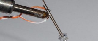
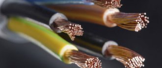
In a charger cable, most often the red wire is positive and the black wire is negative. The white and green wires are used to transmit data.
If the wires do not have color or markings, power is transmitted through the outermost wires on the left and right.
To ensure that the consumer does not get confused which sign (“+” or “-“) and in what place is located on the charger, manufacturers try to mark the wires with different colors.
Basically, “+” corresponds to red, “-“ to black, and less often blue.
On the charger of almost any electrical device, the minus is usually indicated in blue or black, but the plus can be almost any color, but most often it is red and immediately attracts attention.
Yes, it's very simple. All wires on the charger are either positive or negative by color. For example, the red color of the wire always means a plus, and the black and blue wires always mean a minus.
Connection diagram by wire colors on the radio
High-quality sound makes car trips much more enjoyable, but before you can enjoy your favorite music, you need to connect the radio correctly. This procedure is not very complicated, but due to the fact that each car and radio manufacturer uses its own connectors, some installation difficulties may arise. Connecting the radio according to the color of the wires will come to the rescue.
ISO connector
Wire Classification Options
The typical cable name contains letters and numbers. By decoding these symbols you can find out the main characteristics of products in this category:
- conductor (shell) materials;
- number of cores;
- cross-sectional area;
- Extra options.
Example of decoding (AVBbv-ng):
- A – the core is made of aluminum (copper is not marked);
- B – insulating shells are made of PVC;
- BB – protection against mechanical damage, made of steel tape without a damping gasket;
- ng – components that prevent combustion have been added to the polymer shell.
Marking of wires for alternating three-phase current
The special color designation of the shell helps to determine the purpose of individual lines even without studying the accompanying design documentation:
- gray, purple, orange or red wire – phase;
- yellow and green stripes – grounding;
- blue or a combination of white and blue stripes is neutral.
Such designations simplify installation operations when laying power lines during the assembly of electrical panels. It is especially important to eliminate errors when hidden installation of communications inside building structures is used. In this case, correcting incorrect actions will be accompanied by increased costs.
Micro USB connector pinout
To begin with, we present the wiring for this specification.
Micro USB v 2.0 connector wiring
As can be seen from the figure, this is a 5 pin connection; both the plug (A) and socket (B) have four contacts. Their purpose and digital and color designation correspond to the accepted standard, which was given above.
Description of the micro USB connector for version 3.0.
For this connection, a characteristically shaped 10 pin connector is used. In fact, it consists of two parts of 5 pin each, and one of them fully corresponds to the previous version of the interface. This implementation is somewhat confusing, especially considering the incompatibility of these types. Probably, the developers planned to make it possible to work with connectors of earlier modifications, but subsequently abandoned this idea or have not yet implemented it.
MicroUSB connector layout for version 3.0
The figure shows the pinout of the plug (A) and the appearance of the micro USB socket (B).
Contacts 1 to 5 fully correspond to the second generation micro connector, the purpose of the other contacts is as follows:
- 6 and 7 – data transmission via high-speed protocol (SS_TX- and SS_TX+, respectively).
- 8 – mass for high-speed information channels.
- 9 and 10 – data reception via high-speed protocol (SS_RX- and SS_RX+, respectively).
Color of wires plus (+) and minus (-) in DC networks
Is the red wire positive or negative? Such questions arise when working with DC electrical circuits.
Red
To remember which plus is red or black, they use the name of a well-known international organization - the Red Cross. This phrase suggests that red means plus.
Black
Black color indicates the negative conductor. These markings can be seen on typical household equipment:
- power supplies;
- audio, video equipment;
- other devices with electronic software control units.
Plus
The polarity of conductors must be observed when repairing standard electrical equipment of cars. In some situations, confusion with plus and minus is accompanied by a violation of the functional state.
Minus
The high power of connected consumers increases the responsibility for performing repair and adjustment work. In such situations, it is necessary to eliminate errors in determining polarity. Strong direct current is used to supply electricity:
- warehouse and municipal transport;
- lifting mechanisms;
- sensors and automation.
Which wire is plus, blue or brown?
phase wire color brown, black, green, yellow, orange, gray, white, pink, turquoise, red; the neutral working wire should be blue (N); the combined neutral working and protective conductor (PEN) should be blue and have yellow-green stripes at the ends.
Interesting materials:
How is identity verification done? How does a purchase on Wildberries work? How does the eyebrow correction procedure take place? How does the process of photosynthesis occur in brief? How does the process of glycolysis occur? How does reproduction occur in higher plants? How does rigor mortis occur? How do you conceive twins? How to get to Sokolniki Park? How to get training at Tinkoff Investments?
Wire colors in electrical wiring
The color identification scheme is convenient not only for installation. As a rule, different contractors install and operate electrical wiring. Compliance with standards prevents errors during repair work and in the modernization process.
Something to remember! Domestic standards have changed several times over the past decades. Currently, the markings discussed above are used.
Color of zero working and zero protective wires
The color options for the shells will help you recognize the intended purpose of the conductors:
- blue – working zero;
- transverse or longitudinal combinations of yellow and green stripes - protective zero;
- main blue with a change to a combination of yellow and green stripes at the junctions - combined working and protective zero.
Independent work
It is often necessary to find zero, grounding, and phase. As mentioned above, negligence is not always the cause of color confusion in wires. Not every homeowner wants to spend time and money on completely replacing existing wiring. But even in this case, you can use cores with different insulation colors to mark them upon completion of work.
If the previous owner of the apartment or an electrician did not bother with marking, then any white conductor, after independent research, can be marked yourself.
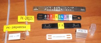
Method 1 – colored electrical tape
There will be no problems with purchasing multi-colored material. Another positive aspect of its use is that forgetful home craftsmen have an excellent opportunity to make written marks on it.
You can mark the wires using colored electrical tape.
Method 2 - cambrics
Heat shrink tubing of various colors can be placed on the white conductor after repair work. According to the requirements of GOST and PUE, marking must be carried out in a certain way: the wire is marked at the point of connection with the bus.
Such forethought will facilitate further work and will not go unnoticed by those who will repair the electrical network in the future.
It is important to create new wire color markings only in accordance with modern standards. It is imperative to observe safety precautions when working, and if possible, involve a specialist for advice and assistance - electricity is not the case when it is better to learn from your own mistakes.
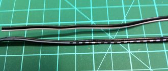
How to determine ground, zero and phase on wires if there are no markings
It is more difficult to determine in practice than in theory. Not all manufacturers comply with the standards. Therefore, when laying a two-phase 220 V network with grounding, you have to use a VVG cable with blue, brown and red colors. Combinations may be different, but without complying with regulatory requirements.
For your information. In old wiring from “Soviet times” there is no color marking. Identical white (gray) shells do not allow the purpose and correspondence of the lines to be known by simple visual inspection.
To avoid problems, it is recommended to carry out installation work using the same type of cable products. When color coding is not available, it should be created at the joints using insulating tape or heat shrink tubing. The latter option is preferable, as it is designed to maintain integrity for a long time.
Below are methods for determining phase and neutral wires with the advantages and disadvantages of each option. In any case, first clarify the network parameters. In old houses, for example, a two-wire connection scheme with a single working and grounding conductor is often used.
The figure shows a modern network with separate grounding and working zero connections. It is possible to connect three- and single-phase loads.
Determining the phase using an indicator screwdriver
Touching the tip of such a device to the phase wire closes the current circuit. This is accompanied by the warning lamp or LED lighting up. A built-in resistor limits the current to a safe level.
Advantages of the indicator:
- minimum cost;
- compactness;
- reliability;
- durability;
- autonomy;
- good protection from adverse external influences.
The disadvantage is the limited measurement accuracy. Under certain conditions, false positives cannot be ruled out.
Determination of ground, zero and phase using a test lamp
To reproduce this technology, you need to prepare a simple design. An incandescent lamp designed for the appropriate mains voltage is screwed into a standard socket. Connect wires of sufficient length to perform work operations in a specific location.
Next, connect one of the wires to the known zero line. Others sequentially check other cable cores. Lighting of the lamp indicates the presence of a phase.
Using a measuring device
When checking a 220 V household network, you do not need to know how to determine the polarity. The power supply is organized using alternating current, so set the multimeter switch to the appropriate position. Touching the phase-zero (phase-ground) wires with the probes is accompanied by an indication of the corresponding voltage (≈220 V). The potential difference between the neutral conductor and ground is minimal.
For your information. When checking an old two-wire circuit, one of the probes touches the reinforcement in a concrete slab, a radiator of a heating system, or another grounded element of a building structure.
When switching to constant voltage, the multimeter will show where the plus and minus are. In the absence of reliable information about the electrical parameters in the circuit, they begin with the maximum measurement range with a sequential transition to smaller values with insufficient accuracy.
Such a “device” is useful for testing DC circuits in the absence of specialized measuring instruments. Bubbles near the negative wire are the release of hydrogen during the electrolysis reaction. The area near the plus will take on a greenish tint after a few minutes.
Using LED
You can create a control device with your own hands by analogy with an indicator screwdriver. Instead of a light bulb, install AL 307 or another LED with similar characteristics. A 100-120 kOhm resistor with a power of 1-2 W is added in series to the circuit.
How to correctly determine the polarity on wires in a car
If the voltage on the car is checked, the course is set to search for a constant one. 20W is the correct setting if you are testing the battery. Therefore, you need to adjust the dial to the desired range/setting and connect the probes to whatever component you want to get a reading for.
You may be interested in: Features of capacitor calculation
How to check a headlight with a multimeter
Multimeter
To check the headlight wiring, you need to find the ground wire. There are 2-4 wires coming from the connector that connects to the light bulb. Where there are two or three wires, only one of them is ground, while four-wire connectors will have two grounds.
To test the wires on the headlight, you need to set the multimeter to resistance. You can place one of the probes on the ground and the other on the negative pole of the car battery.
Note! If continuity is not read, then there is a problem with the ground wire, meaning it needs to be replaced.
How to Test a Car's Ground Wire Using a Multimeter
To test ground wires, start by measuring resistance. Test along the wiring to check the reading is 5 ohms or less. If it exceeds, you will need to check the wire further. You need to switch the multimeter to constant voltage and turn on any electrical part that is having problems. It's worth double-checking the wire to make sure the reading doesn't exceed 0.05V. If it does, you'll need to use a different ground location or use a tie strap.
How to Check if a Fuse Has Blown Using a Multimeter
Troubleshooting a fuse using a multimeter is extremely easy. You need to set the multimeter to the lowest ohm setting and place the probes on both sides of the fuse covers. Fuses do not have polarity, so the contacts used will not show values.
Circuit breakers
Note! If the resistance value is very low, then the fuse is working perfectly. If the resistance value does not change after connecting the contacts, the fuse has blown.
You can also test the fuse using a test light. You need to turn on the key and touch both sides of the fuse with the tip of the test light. If it lights up, the fuse is good. If it does not light up, the fuse needs to be replaced.
How to use a multimeter from a car battery
If you're having trouble starting your car, one of the most common reasons is a weak battery. This is something that can be easily checked using a multimeter, which will also give an accurate idea of how much charge the battery actually has left. Testing your car battery first is a great way to rule out a likely cult for many electrical problems.
When testing a car battery, you need to check the voltage by setting the multimeter to 20 V DC. It is necessary to connect contacts to both terminals of the battery that match the color. It is better to turn on the headlights to get accurate information regarding the charge.
Important! The headlights must be turned on when the engine is stalled.
In most cases the reading will be somewhere between 11.8 V and 12.6 V. The higher the voltage reading, the more charge there is in the battery. A reading of 12.5V means the battery is almost fully charged, while a reading of 11.9V means the battery should be replaced soon.
You might be interested in: Features of using rosin
Checking the charger
Electronic devices use adapters to convert alternating current supplied from wall outlets to direct current. Once converted to direct current, current flows in one direction, hence the term direct current.
What color is the positive wire on the charger?
Note! One wire is positive, which conducts current to the device, and the other is negative, which completes the circuit. The direction of flow is called polarity and is marked on chargers using a diagram. If there is no diagram on the charger, it is worth checking the polarity.
The color polarity of the charger wires does not matter.
To determine if the charger is fit for use, do the following:
- Connect the charger to a power outlet.
- Turn on the multimeter and set the settings to DC voltage. Most multimeters indicate this setting as VDC.
- Insert the red positive contact into the hole in the charger tip.
- Touch the black negative terminal and the outer metal part of the charger tip.
- Monitor the multimeter readings. You may see a positive or negative number indicating the DC output voltage of the charger. If the number is positive, then the polarity on the inside of the charger tip is positive. If the number is negative, then the polarity inside is negative.