Traction force of a DC electromagnet.
The dependence of the traction force of an electromagnet on the working gap at a constant current in the winding is called the static traction characteristic of the electromagnet
P=f (δ) at I=const. If the electromagnet, instead of linear movement of the armature, provides for its rotation, then the static characteristic is understood as the dependence of the moment M on the armature on the angle of its rotation a, taken at a constant current in the winding.
The traction force developed by an electromagnet can be calculated using Maxwell's formula, derived from the analysis of the magnetic field acting on the surface of the poles. If the field in the working gap is uniform and the poles are unsaturated, then for an electromagnet with one working gap
traction force
Р = BIδ S / 2μ0 = Φ²δ / 2 μ0 S
where Bδ and Φδ are induction, T, and magnetic flux, Wb, in the working gap;
S - pole area, m2;.
μ0 – constant magnetic permeability, Gn/m;
δ- gap length
If the valve solenoid has two gaps
at the same value Φδ of the magnetic flux in the gap,
the traction force doubles
:
Р= ΦІδ / μ0 S
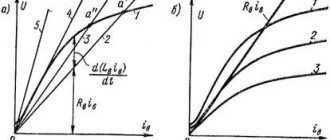
The dependence P=f (δ) at a constant MMF, called the static traction characteristic, is presented in Fig. 5.18 (curve 1).
As δ decreases, the traction force increases sharply and at δ = 0 tends to infinity.
In fact, at δ >0, the magnetic flux increases and the drop in the magnetic potential in the magnetic core increases, and only part of the MMF is applied to the air gap. Curve 2 in Fig. 5.18 depicts the dependence P = f (δ), taken experimentally. At large gaps, when the magnetic flux in the magnetic core is small and the drop in the magnetic potential in the steel can be neglected, the calculated and experimental curves almost coincide. For small gaps, the traction force has a finite value.
2) Traction force of an alternating current electromagnet . The magnetic resistance of steel, the active resistance of the winding and losses in steel are zero; voltage, current and magnetic flux change sinusoidally. With alternating voltage, the current in the winding is determined mainly by its inductive reactance, which changes sharply when the armature moves.
For a system with two gaps, traction force: Рm = Φ²δ / 2 μ0 S
Instantaneous traction force in a single-phase electromagnet
can be expressed through the average Р = ( Рm/2) –( Рm/2) cos2ωt
The instantaneous value of the traction force pulsates with double frequency in relation to the frequency of current and voltage.
The first term is the average value of the force over the period. The second term represents the variable component of the force and its presence leads to harmful vibrations of the armature in the electric magnet.
A change in force over time negatively affects the operation of the electromagnet. Since a single-phase electric magnet has 2 poles of the same cross-section, through which the same flow passes, the instantaneous force acting on the armature is equal to Рres = 2 R. To attract the armature, it is necessary that the average value of the traction force be greater than the opposing force of the spring.
At certain points in time, the opposing force of the spring becomes greater than the traction force, which causes the armature to separate from the core. Then, as the traction force increases, the armature is again attracted to the core. As a result, the armature vibrates continuously, which disrupts the operation of the contacts. Noise is created and the magnetic system becomes loose. To attract the armature, it is necessary that this average value be greater than the opposing force of the spring
To eliminate armature vibration in single-phase electric magnets, short-circuit turns are used
. The tip of the pole is split, and a short-circuit coil of copper or aluminum is mounted on its larger part. Magnetic flux F created by the magnetizing winding. It branches into 2 parts Fn and Fe (from the shielding coil). This reduces the amplitude of the force pulsation. The resulting force acting on the anchor is not lower than a certain minimum value.
Fig13
In a three-phase electromagnet, the traction forces developed under each pole are equal
Ra= Рmsin²ωt,
Рв= Рmsin²(ωt – 2/3 π),
Рс= Рmsin²(ωt – 4/3 π),
resultant force acting on the anchor
Р=Ra+Рb+Рс=3Рm/2
The resulting force acting on the anchor does not change over time
.
However, vibration is not completely eliminated
. When the magnetic flux in each phase passes through zero, the force developed by this phase is also zero. As a result, the point of application of the resultant traction force of all three phases moves along the armature body. Since the point of application of the opposing force is constant, vibration of the armature occurs because of this.
e) Comparison of static traction characteristics of electric. DC and AC magnets .
1. If the pole areas of the electromagnets are the same and the maximum values of induction B m in the working gaps are the same, then the maximum value of the electric traction force. The alternating current magnet is equal to the traction force of the electric current. DC magnet. : Рm = Ф2 / 2μ0 S =
P = B²S /2 μ0
2. Since the average value of force with alternating current Рср = Рm / 2, then the average force developed by an alternating current electromagnet is 2 times less
force: developed by a direct current electromagnet.
3. The disadvantage of alternating current electromagnets is the vibration of the armature. The use of a short-circuited coil to reduce vibrations leads to a decrease in the average value of traction force
.
4. It is known that the traction force varies inversely with the square of the gap
.
In this regard, the DC
either has a small working stroke of the armature to provide greater traction force, or the winding must have a large MMF to create the necessary magnetic flux with a larger air gap.
5. AC electromagnets are characterized by a weak dependence of the force on the size of the air gap. This is explained by the fact that as the gap changes, the
inductive reactance of the winding.
As the gap grows , its magnetic resistance increases, but the current in the winding also increases, so the flux in the gap drops only due to the active voltage drop in the winding.
In this regard, an alternating current electric magnet can operate at relatively large armature strokes.
6. The disadvantages of alternating current electric magnets include the fact that the traction characteristic, which slightly increases along the armature, limits the possibility of matching it with the load characteristic.
The traction characteristics of an AC electromagnet can be improved by feeding the winding with rectified alternating current.
In AC electromagnets, additional energy has to be expended to compensate for active losses in steel. This leads to an increase in the magnetizing current in the winding. Materials for electronics AC magnets must have low eddy current losses and hysteresis. Magnetic cores for such electrical magnets are made from laminated plates. The higher the current frequency, the smaller the thickness of the plates should be. For high-speed electric DC magnets also use laminated magnetic cores, because At the same time, eddy currents, which slow down the flow increase, are reduced.
Main characteristics of an electromagnet
Fig14
Main parameters:
Power consumed by an electric magnet - the maximum power can be limited both by the amount of permissible heating of its winding and by the power conditions of the electric magnet winding.
Safety factor - the ratio of the MMF corresponding to the steady current value to the MMF of the operation of Kz = Fу/Fср = Iу/Iср >1
Triggering parameter - the minimum value of current or voltage at which the electric magnet is triggered (armature movement)
Release (return) parameter - the maximum value of current or voltage at which the armature returns to its original position. The ratio of the release current to the operation current is called the return coefficient Kv = Fв/Fср = Iв/Iср = 0.1…0.9
The dependence of the traction force of an electromagnet on the working gap at a constant current in the winding is called the static traction characteristic of the electromagnet
P=f (δ) at I=const. If the electromagnet, instead of linear movement of the armature, provides for its rotation, then the static characteristic is understood as the dependence of the moment M on the armature on the angle of its rotation a, taken at a constant current in the winding.
The traction force developed by an electromagnet can be calculated using Maxwell's formula, derived from the analysis of the magnetic field acting on the surface of the poles. If the field in the working gap is uniform and the poles are unsaturated, then for an electromagnet with one working gap
traction force
Р = BIδ S / 2μ0 = Φ²δ / 2 μ0 S
where Bδ and Φδ are induction, T, and magnetic flux, Wb, in the working gap;
S - pole area, m2;.
μ0 – constant magnetic permeability, Gn/m;
δ- gap length
If the valve solenoid has two gaps
at the same value Φδ of the magnetic flux in the gap,
the traction force doubles
:
Р= ΦІδ / μ0 S
The dependence P=f (δ) at a constant MMF, called the static traction characteristic, is presented in Fig. 5.18 (curve 1).
As δ decreases, the traction force increases sharply and at δ = 0 tends to infinity.
In fact, at δ >0, the magnetic flux increases and the drop in the magnetic potential in the magnetic core increases, and only part of the MMF is applied to the air gap. Curve 2 in Fig. 5.18 depicts the dependence P = f (δ), taken experimentally. At large gaps, when the magnetic flux in the magnetic core is small and the drop in the magnetic potential in the steel can be neglected, the calculated and experimental curves almost coincide. For small gaps, the traction force has a finite value.
2) Traction force of an alternating current electromagnet . The magnetic resistance of steel, the active resistance of the winding and losses in steel are zero; voltage, current and magnetic flux change sinusoidally. With alternating voltage, the current in the winding is determined mainly by its inductive reactance, which changes sharply when the armature moves.
For a system with two gaps, traction force: Рm = Φ²δ / 2 μ0 S
Instantaneous traction force in a single-phase electromagnet
can be expressed through the average Р = ( Рm/2) –( Рm/2) cos2ωt
The instantaneous value of the traction force pulsates with double frequency in relation to the frequency of current and voltage.
The first term is the average value of the force over the period. The second term represents the variable component of the force and its presence leads to harmful vibrations of the armature in the electric magnet.
A change in force over time negatively affects the operation of the electromagnet. Since a single-phase electric magnet has 2 poles of the same cross-section, through which the same flow passes, the instantaneous force acting on the armature is equal to Рres = 2 R. To attract the armature, it is necessary that the average value of the traction force be greater than the opposing force of the spring.
At certain points in time, the opposing force of the spring becomes greater than the traction force, which causes the armature to separate from the core. Then, as the traction force increases, the armature is again attracted to the core. As a result, the armature vibrates continuously, which disrupts the operation of the contacts. Noise is created and the magnetic system becomes loose. To attract the armature, it is necessary that this average value be greater than the opposing force of the spring
To eliminate armature vibration in single-phase electric magnets, short-circuit turns are used
. The tip of the pole is split, and a short-circuit coil of copper or aluminum is mounted on its larger part. Magnetic flux F created by the magnetizing winding. It branches into 2 parts Fn and Fe (from the shielding coil). This reduces the amplitude of the force pulsation. The resulting force acting on the anchor is not lower than a certain minimum value.
Fig13
In a three-phase electromagnet, the traction forces developed under each pole are equal
Ra= Рmsin²ωt,
Рв= Рmsin²(ωt – 2/3 π),
Рс= Рmsin²(ωt – 4/3 π),
resultant force acting on the anchor
Р=Ra+Рb+Рс=3Рm/2
The resulting force acting on the anchor does not change over time
.
However, vibration is not completely eliminated
. When the magnetic flux in each phase passes through zero, the force developed by this phase is also zero. As a result, the point of application of the resultant traction force of all three phases moves along the armature body. Since the point of application of the opposing force is constant, vibration of the armature occurs because of this.
e) Comparison of static traction characteristics of electric. DC and AC magnets .
1. If the pole areas of the electromagnets are the same and the maximum values of induction B m in the working gaps are the same, then the maximum value of the electric traction force. The alternating current magnet is equal to the traction force of the electric current. DC magnet. : Рm = Ф2 / 2μ0 S =
P = B²S /2 μ0
2. Since the average value of force with alternating current Рср = Рm / 2, then the average force developed by an alternating current electromagnet is 2 times less
force: developed by a direct current electromagnet.
3. The disadvantage of alternating current electromagnets is the vibration of the armature. The use of a short-circuited coil to reduce vibrations leads to a decrease in the average value of traction force
.
4. It is known that the traction force varies inversely with the square of the gap
.
In this regard, the DC
either has a small working stroke of the armature to provide greater traction force, or the winding must have a large MMF to create the necessary magnetic flux with a larger air gap.
5. AC electromagnets are characterized by a weak dependence of the force on the size of the air gap. This is explained by the fact that as the gap changes, the
inductive reactance of the winding.
As the gap grows , its magnetic resistance increases, but the current in the winding also increases, so the flux in the gap drops only due to the active voltage drop in the winding.
In this regard, an alternating current electric magnet can operate at relatively large armature strokes.
6. The disadvantages of alternating current electric magnets include the fact that the traction characteristic, which slightly increases along the armature, limits the possibility of matching it with the load characteristic.
The traction characteristics of an AC electromagnet can be improved by feeding the winding with rectified alternating current.
In AC electromagnets, additional energy has to be expended to compensate for active losses in steel. This leads to an increase in the magnetizing current in the winding. Materials for electronics AC magnets must have low eddy current losses and hysteresis. Magnetic cores for such electrical magnets are made from laminated plates. The higher the current frequency, the smaller the thickness of the plates should be. For high-speed electric DC magnets also use laminated magnetic cores, because At the same time, eddy currents, which slow down the flow increase, are reduced.
Main characteristics of an electromagnet
Fig14
Main parameters:
Power consumed by an electric magnet - the maximum power can be limited both by the amount of permissible heating of its winding and by the power conditions of the electric magnet winding.
Safety factor - the ratio of the MMF corresponding to the steady current value to the MMF of the operation of Kz = Fу/Fср = Iу/Iср >1
Triggering parameter - the minimum value of current or voltage at which the electric magnet is triggered (armature movement)
Release (return) parameter - the maximum value of current or voltage at which the armature returns to its original position. The ratio of the release current to the operation current is called the return coefficient Kv = Fв/Fср = Iв/Iср = 0.1…0.9
The device of electromagnets
Despite the extensive, judging by the classification described above, the number of different options for electromagnets, there are certain nodes of the same type that are found in all electromagnets.
- A coil with a magnetizing winding located on it
- The moving part of the electromagnet is the armature
- Fixed part - yoke and core
There are air gaps between the anchor and the fixed parts. So, air gaps can be useful or parasitic. Useful gaps are located along the possible path of movement of the anchor. The parasitic gaps lie outside the movement of the armature.
There is also the concept of a pole. Poles are the surfaces of the magnetic circuit that limit the useful air gap.
The design forms of AC electromagnets do not have many options, due to the fact that the core is made from sheets of electrical steel. This is necessary to combat eddy currents.
general characteristics
An electromagnet is a simple coil of wire that is connected to a source that transmits direct current.
By connecting to a source of direct current (as well as voltage), the coil and wire begin to receive energy resources and create a magnetic field that is similar to the field that is formed in permanent bar magnets. The density of the magnetic flux is always proportional to the amount of electric current flowing through the thickness of the coil. The polarity of the electromagnet is determined by the direction of the current. The formation mechanism involves (the simplest option) winding a wire around a core made of metal, through which electricity from a certain source is then passed. If the internal cavity of the coil is filled with air, then it is called a solenoid.
An electromagnet is a device through which an electromagnetic field can be created. The main characteristic is his ability to control the strength of a given field, polarity and its shape. In this case, the strength of the magnetic field is controlled by the amount of used electric current that flows through the coil. The polarity can be set by determining in which direction the flowing current should be moved. The shape of the magnetic field depends on the shape of the metal core, which serves as the “rod” for the winding wire. Do not forget that the poles of an electromagnet are determined in the same way as in solenoids, according to the physical rule of the right hand. P.P.R. also called the gimlet rule, which is a mnemonic device by which the direction of vector products and the right basis is determined.
You can increase the strength of an electromagnet, or rather its field, using:
- the use of “soft” iron cores;
- the use of large numbers of turns;
- application of electric current on a large scale.
How does an electromagnet work?
The EV operation cycle itself represents the following sequence of actions. First, a current of such magnitude is supplied to the winding that the magnetic forces become greater than the forces holding the armature at rest.
Next, the anchor will detach from its state of rest and move the anchor to the end point of the useful gap. This is the first stage.
At the second stage, the EM armature is pulled up and current flows through it. As we know, current creates a thermal effect over time. Therefore, the operating time should not exceed the permissible limit. At this stage, the traction force of the electromagnet is maximum.
The last, Third stage is similar to the first - the current decreases to zero, the magnetic forces become less than the forces that return the armature to a state of rest, the armature disappears. Next, the electromagnet cools down.
If the nature of its work is periodically repeating, then in the time before the next cycle, it needs time to cool down.