How to route wires correctly
The main provisions that are followed when installing electrical wiring in an apartment with your own hands:
- accessibility of all key elements (meter, distribution boxes, machines);
- the height from the floor to the switch is assumed to be 0.6-1.5 m, and it is installed so that the door does not interfere with access;
- the installation height of sockets is taken to be 0.5-0.8 m from the floor level to prevent water from entering during flooding;
- the distance from the outlet to the gas or electric stove, other communications must be at least 0.5 m;
- Electrical wiring is allowed only vertically or horizontally; a wiring diagram must be drawn up.
The standards recommend the following principle for calculating the optimal number of sockets: for every 6 m2 - 1 socket. You can deviate from this rule for the kitchen. Here you can increase the number of connection points.
Electrical wiring in the apartment is carried out in such a way as to prevent contact of wires with metal elements of the building structure. If the channel is intended for laying several wiring lines with your own hands, leave a distance of at least 3 mm between them. It is best to protect each with a separate box or corrugated sleeve. The connection of individual parts is carried out in a distribution box. Open parts are carefully insulated. Do not connect copper and aluminum wires together.
- You can be sure that the electrical wiring in the apartment is carried out in compliance with all standards. So it's safe.
- The power of the devices is taken into account, therefore, you can use any equipment without fear.
Legislative framework of the Russian Federation
valid Editorial from 20.05.2003
detailed information
| Name of document | “RULES FOR ELECTRICAL INSTALLATIONS. SECTION 2. SEWERAGE OF ELECTRIC POWER (Edition 7)" (approved by the Ministry of Fuel and Energy of the Russian Federation) |
| Document type | rules |
| Receiving authority | Ministry of Energy of the Russian Federation |
| Document Number | PUE |
| Acceptance date | 01.01.1970 |
| Revision date | 20.05.2003 |
| Date of registration with the Ministry of Justice | 01.01.1970 |
| Status | valid |
| Publication |
|
| Navigator | Notes |
“RULES FOR ELECTRICAL INSTALLATIONS. SECTION 2. SEWERAGE OF ELECTRIC POWER (Edition 7)" (approved by the Ministry of Fuel and Energy of the Russian Federation)
Laying cable lines in cable structures
2.3.112. Cable structures of all types must be carried out taking into account the possibility of additional laying of cables in the amount of 15% of the number of cables provided for by the project (replacement of cables during installation, additional laying in subsequent operation, etc.).
2.3.113. Cable floors, tunnels, galleries, overpasses and shafts must be separated from other rooms and adjacent cable structures by fireproof partitions and ceilings with a fire resistance limit of at least 0.75 hours. Extended tunnels must be divided by the same partitions into compartments no more than 150 m long, if available power and control cables and no more than 100 m in the presence of oil-filled cables. The area of each double floor compartment should be no more than 600 m2.
Doors in cable structures and partitions with a fire resistance limit of 0.75 hours must have a fire resistance limit of at least 0.75 hours in electrical installations listed in 2.3.76, and 0.6 hours in other electrical installations.
Exits from cable structures must be provided outside or into premises with production categories G and D. The number and location of exits from cable structures must be determined based on local conditions, but there must be at least two. If the length of the cable structure is no more than 25 m, it is allowed to have one output.
Doors of cable structures must be self-closing, with sealed doorways. Exit doors from cable structures must open outward and must have locks that can be unlocked from cable structures without a key, and doors between compartments must open in the direction of the nearest exit and be equipped with devices that keep them in the closed position.
Walk-through cable racks with service bridges must have entrances with stairs. The distance between the entrances should be no more than 150 m. The distance from the end of the overpass to the entrance to it should not exceed 25 m.
Entrances must have doors that prevent free access to the overpasses for persons not involved in cable maintenance. Doors must have self-locking locks that can be opened without a key from the inside of the overpass.
The distance between the entrances to the cable gallery when laying cables no higher than 35 kV in it should be no more than 150 m, and when laying oil-filled cables - no more than 120 m.
External cable racks and galleries must have main load-bearing building structures (columns, beams) made of reinforced concrete with a fire resistance limit of at least 0.75 hours or rolled steel with a fire resistance limit of at least 0.25 hours.
Load-bearing structures of buildings and structures that can be dangerously deformed or reduce mechanical strength when groups (streams) of cables laid near these structures on external cable overpasses and galleries burn, must have protection that provides a fire resistance limit of the protected structures of at least 0.75 hours.
Cable galleries must be divided into compartments by fireproof fire partitions with a fire resistance limit of at least 0.75 hours. The length of the gallery compartments should be no more than 150 m when laying cables up to 35 kV and no more than 120 m when laying oil-filled cables. The above requirements do not apply to external cable galleries that are partially closed.
2.3.114. In tunnels and canals, measures must be taken to prevent process water and oil from entering them, and drainage of soil and storm water must also be ensured. The floors in them must have a slope of at least 0.5% towards the water collectors or storm drains. The passage from one tunnel compartment to another, when they are located at different levels, must be carried out using a ramp with an inclination angle of no higher than 15°. The construction of steps between tunnel compartments is prohibited.
In cable channels constructed outdoors and located above the groundwater level, an earthen bottom with a drainage bedding 10-15 cm thick of compacted gravel or sand is allowed.
Drainage mechanisms must be provided in tunnels; In this case, it is recommended to use automatic start-up depending on the water level. Starting devices and electric motors must be designed to allow them to operate in particularly damp places.
When crossing overpasses and walk-through galleries from one mark to another, a ramp must be made with a slope of no more than 15°. As an exception, staircases with a slope of 1:1 are allowed.
2.3.115. Cable ducts and double floors in switchgears and rooms must be covered with removable fireproof slabs. In electrical machinery and similar rooms, it is recommended to cover the channels with corrugated steel, and in control panel rooms with parquet floors - with wooden boards with parquet, protected from below with asbestos and asbestos with tin. The covering of ducts and double floors must be designed to allow the movement of related equipment over it.
2.3.116. Cable ducts outside buildings must be backfilled on top of removable slabs with a layer of earth at least 0.3 m thick. In fenced areas, backfilling of cable ducts with earth on top of removable slabs is not necessary. The weight of an individual floor slab removed manually should not exceed 70 kg. The slabs must have a lifting device.
2.3.117. In areas where molten metal, high-temperature liquids, or substances that have a destructive effect on the metal sheaths of cables may be spilled, the construction of cable channels is not allowed. In these areas, it is also not allowed to install hatches in sewers and tunnels.
2.3.118. Underground tunnels outside buildings must have a layer of earth at least 0.5 m thick on top of the ceiling.
2.3.119. When laying cables and heat pipes together in buildings, additional heating of the air by the heat pipe at the location of the cables at any time of the year should not exceed 5°C, for which ventilation and thermal insulation on the pipes should be provided.
2.3.120. In cable structures, it is recommended to lay cables in entire construction lengths, and the placement of cables in structures should be done in accordance with the following:
1. Control cables and communication cables should be placed only under or only above power cables; however, they should be separated by a partition. At intersections and branches, it is allowed to lay control cables and communication cables above and below power cables.
2. Control cables may be laid next to power cables up to 1 kV.
3. Power cables up to 1 kV are recommended to be laid over cables above 1 kV; however, they should be separated by a partition.
4. Various groups of cables: working and backup cables above 1 kV of generators, transformers, etc., supplying power receivers of category I, it is recommended to be laid at different horizontal levels and separated by partitions.
5. The dividing partitions specified in paragraphs 1, 3 and 4 must be fireproof with a fire resistance rating of at least 0.25 hours.
When using automatic fire extinguishing using air-mechanical foam or sprayed water, the partitions specified in clauses 1, 3 and 4 may not be installed.
On external cable overpasses and in external partially enclosed cable galleries, the installation of dividing partitions specified in clauses 1, 3 and 4 is not required. In this case, mutually redundant power cable lines (with the exception of lines to electrical receivers of special group I category) should be laid with a distance between them of at least 600 mm and are recommended to be located: on overpasses on both sides of the span supporting structure (beams, trusses); in the galleries on opposite sides of the aisle.
2.3.121. Oil-filled cables should, as a rule, be laid in separate cable structures. It is allowed to lay them together with other cables; in this case, oil-filled cables should be placed in the lower part of the cable structure and separated from other cables by horizontal partitions with a fire resistance limit of at least 0.75 hours. The same partitions should be used to separate oil-filled cable lines from one another.
2.3.122. The need for the use and scope of automatic stationary means of detecting and extinguishing fires in cable structures must be determined on the basis of departmental documents approved in the prescribed manner.
Fire hydrants must be installed in the immediate vicinity of the entrance, hatches and ventilation shafts (within a radius of no more than 25 m). For overpasses and galleries, fire hydrants must be located in such a way that the distance from any point on the axis of the overpass and gallery route to the nearest hydrant does not exceed 100 m.
2.3.123. In cable structures, the laying of control cables and power cables with a cross-section of 25 mm2 or more, with the exception of unarmored cables with a lead sheath, should be carried out along cable structures (consoles).
Control unarmored cables, power unarmored cables with a lead sheath and unarmored power cables of all designs with a cross-section of 16 mm2 or less should be laid on trays or partitions (solid or non-solid).
It is allowed to lay cables along the bottom of the channel with a depth of no more than 0.9 m; in this case, the distance between a group of power cables above 1 kV and a group of control cables must be at least 100 mm, or these groups of cables must be separated by a fireproof partition with a fire resistance rating of at least 0.25 hours.
The distances between individual cables are given in table. 2.3.1.
Filling power cables laid in channels with sand is prohibited (for an exception, see 7.3.110).
In cable structures, the height, width of passages and the distance between structures and cables must be no less than those given in table. 2.3.1. Compared to the distances given in the table, a local narrowing of passages up to 800 mm or a reduction in height to 1.5 m over a length of 1.0 m is allowed with a corresponding reduction in the vertical distance between cables for one-sided and two-sided structures.
Table 2.3.1.
Shortest distance for cable structures
| Distance | Minimum dimensions, mm, when laying | |
| in tunnels, galleries, cable floors and overpasses | in cable ducts and double floors | |
| Clear height | 1800 | Not limited, but not more than 1200 mm |
| Horizontally in the clear between structures when they are located on both sides (passage width) | 1000 | 300 at a depth of up to 0.6 m; 450 at a depth of more than 0.6 to 0.9 m; 600 at a depth of more than 0.9 m |
| Horizontally in the light from the structure to the wall with a one-sided arrangement (passage width) | 900 | Same |
| Vertically between horizontal structures <*>: | ||
| for power cables voltage: | ||
| up to 10 kV | 200 | 150 |
| 20-35 kV | 250 | 200 |
| 110 kV and above | 300 <**> | 250 |
| for control and communication cables, as well as power cables with a cross-section of up to 3x25 mm2 and voltage up to 1 kV | 100 | |
| Between supporting structures (consoles) along the length of the structure | 800-1000 | |
| Vertically and horizontally in the light between single power cables with voltage up to 35 kV <***> | Not less than cable diameter | |
| Horizontally between control cables and communication cables <***> | Not standardized | |
| Horizontally in the clear between cables with voltage 110 kV and above | 100 | Not less than cable diameter |
<*> The useful length of the console should be no more than 500 mm on straight sections of the route.
<**> When cables are arranged in a triangle 250 mm.
<***> Including for cables laid in cable shafts.
2.3.124. Laying of control cables is allowed in bundles on trays and in multilayers in metal boxes, subject to the following conditions:
1. The outer diameter of the cable bundle must be no more than 100 mm.
2. The height of the layers in one box should not exceed 150 mm.
3. Only cables with the same type of sheaths should be laid in bundles and multilayers.
4. Fastening of cables in bundles, multilayered in boxes, cable bundles to trays should be done in such a way that deformation of the cable sheaths under the influence of its own weight and fastening devices is prevented.
5. For fire safety purposes, fire-barrier belts must be installed inside the boxes: in vertical sections - at a distance of no more than 20 m, as well as when passing through the ceiling; in horizontal sections - when passing through partitions.
6. In each direction of the cable route, a reserve capacity of at least 15% of the total capacity of the boxes should be provided.
Laying power cables in bundles and multi-layers is not allowed.
2.3.125 <*>. In places saturated with underground communications, it is allowed to construct semi-through tunnels with a height reduced in comparison with that provided in the table. 2.3.1, but not less than 1.5 m, subject to the following requirements: the voltage of the cable lines must be no higher than 10 kV; the length of the tunnel should be no more than 100 m; the remaining distances must correspond to those given in the table. 2.3.1; There should be exits or hatches at the ends of the tunnel.
<*> Agreed with the Central Committee of the trade union of workers of power plants and electrical industry.
2.3.126. Oil-filled low-pressure cables must be mounted on metal structures in such a way that the possibility of forming closed magnetic circuits around the cables is excluded; the distance between fastening points should be no more than 1 m.
Steel pipelines of high-pressure oil-filled cable lines can be laid on supports or suspended on hangers; the distance between supports or hangers is determined by the line design. In addition, pipelines must be fixed on fixed supports to prevent thermal deformations in the pipelines under operating conditions.
The loads taken by the supports from the weight of the pipeline should not lead to any movement or destruction of the support foundations. The number of these supports and their locations are determined by the project.
Mechanical supports and fastenings of branching devices on high-pressure lines must prevent swinging of branching pipes and the formation of closed magnetic circuits around them, and insulating gaskets must be provided in places where supports are fastened or touched.
2.3.127. The height of cable wells must be at least 1.8 m; The height of the chambers is not standardized. Cable wells for connecting, locking and semi-locking couplings must have dimensions that ensure installation of the couplings without tearing.
Coastal wells at underwater crossings must be sized to accommodate backup cables and feeders.
A pit must be installed in the floor of the well to collect groundwater and storm water; a drainage device must also be provided in accordance with the requirements given in 2.3.114.
Cable wells must be equipped with metal ladders.
In cable wells, cables and couplings must be laid on structures, trays or partitions.
2.3.128. Hatches for cable wells and tunnels must have a diameter of at least 650 mm and be closed with double metal covers, the bottom of which must have a device for closing with a lock that can be opened from the side of the tunnel without a key. Covers must have provisions for their removal. Indoors, the use of a second cover is not required.
2.3.129. Special protective covers must be installed on connecting couplings of power cables with a voltage of 6-35 kV in tunnels, cable floors and channels to localize fires and explosions that may occur during electrical breakdowns in the couplings.
2.3.130. End couplings on high-pressure oil-filled cable lines must be located in rooms with positive air temperatures or be equipped with automatic heating when the ambient temperature drops below +5°C.
2.3.131. When laying oil-filled cables in galleries, it is necessary to provide heating for the galleries in accordance with the technical specifications for oil-filled cables.
The premises of oil-feeding units of high-pressure lines must have natural ventilation. Underground feeding points may be combined with cable wells; in this case, wells must be equipped with drainage devices in accordance with 2.3.127.
2.3.132. Cable structures, with the exception of overpasses, wells for connecting couplings, channels and chambers, must be provided with natural or artificial ventilation, and the ventilation of each compartment must be independent.
The calculation of ventilation of cable structures is determined based on the temperature difference between incoming and exhaust air of no more than 10°C. At the same time, the formation of hot air bags in narrowing tunnels, turns, bypasses, etc. must be prevented.
Ventilation devices must be equipped with dampers (dampers) to stop the access of air in the event of a fire, as well as to prevent freezing of the tunnel in winter. The design of ventilation devices must ensure the possibility of using automatic shutdown of air access to structures.
When laying cables indoors, overheating of the cables due to increased ambient temperature and the influence of technological equipment must be prevented.
Cable structures, with the exception of wells for connecting couplings, channels, chambers and open overpasses, must be equipped with electric lighting and a network for powering portable lamps and tools. At thermal power plants, the network for powering the tool may not be installed.
2.3.133. Cable laying in collectors, technological galleries and along technological overpasses is carried out in accordance with the requirements of SNiP Gosstroy of Russia.
The shortest clear distances from cable overpasses and galleries to buildings and structures should correspond to those given in Table. 2.3.2.
The intersection of cable racks and galleries with overhead power lines, intra-plant railways and roads, fire passages, cable cars, overhead communication and radio lines and pipelines is recommended to be performed at an angle of at least 30°.
Table 2.3.2.
The shortest distance from cable overpasses and galleries to buildings and structures
| Construction | Normalized distance | Smallest dimensions, m |
| When following in parallel, horizontally | ||
| Buildings and structures with blank walls | From the design of an overpass and gallery to the wall of a building and structure | Not standardized |
| Buildings and structures with walls with openings | Same | 2 |
| In-plant non-electrified railway | From the design of overpasses and galleries to the approach dimensions of buildings | 1 m for galleries and passage overpasses; 3 m for impassable overpasses |
| Intra-factory highway and fire routes | From the structure of the overpass and gallery to the curb stone, outer edge or base of the road ditch | 2 |
| Cable car | From the design of the overpass and gallery to the size of the rolling stock | 1 |
| Overhead pipeline | From the structure of the overpass and gallery to the nearest parts of the pipeline | 0,5 |
| Overhead power line | From the design of the overpass and gallery to the wires | See 2.5.114 |
| When crossing, vertically | ||
| In-plant non-electrified railway | From the bottom mark of the overpass and gallery to the rail head | 5,6 |
| In-plant electrified railway | From the bottom mark of the overpass and gallery: | |
| to the rail head | 7,1 | |
| to the highest wire or supporting cable of the contact network | 3 | |
| Intra-factory highway (fire passage) | From the bottom mark of the overpass and gallery to the road surface (fire passage) | 4,5 |
| Overhead pipeline | From the structure of the overpass and gallery to the nearest parts of the pipeline | 0,5 |
| Overhead power line | From the design of the overpass and gallery to the wires | See 2.5.113 |
| Overhead communication and radio link | Same | 1,5 |
Location of overpasses and galleries in hazardous areas - see Chapter. 7.3, location of overpasses and galleries in fire hazardous areas - see Ch. 7.4.
When running parallel overpasses and galleries with overhead communication and radio lines, the shortest distances between the cables and wires of the communication and radio lines are determined based on the calculation of the influence of cable lines on the communication and radio lines. Communication and radio wires can be located under and above overpasses and galleries.
The minimum height of the cable overpass and gallery in the impassable part of the territory of an industrial enterprise should be taken based on the possibility of laying the bottom row of cables at a level of at least 2.5 m from the planning ground level.
What are the advantages of the method
Open cable routing along walls is most often used not in houses and apartments, but in garden buildings in the country - a garage, a utility block, a bathhouse. Although if you try and choose the right materials, then even in private houses and modern apartments this option for installing electrical wiring will be a winner.
The advantages of open wiring are as follows:
- simpler and faster installation, which even a novice electrician can easily handle;
- fewer tools and materials will be required than when creating hidden electrical wiring;
- You can bring out a new group of wires from the panel or distribution box at any time (for example, if you want to install another socket);
- in some cases, this option has a positive effect on the interior of the room (for example, if you use porcelain rollers and insulators in the bathhouse);
- Repair and maintenance of the line can be carried out without disturbing the decorative finish of the walls.
At the same time, the disadvantages of installing open wiring with your own hands are an increased risk of fire, limited operating conditions and a shorter service life of the electrical network. Please also take into account that the route is more susceptible to mechanical damage than if it is laid in walls.
Do not lay open electrical wiring in the kitchen so that water and heat from the stove get onto the cable lines and sockets; also follow the recommendations described in the article on installing sockets in the kitchen https://samelectrik.ru/rozetki-na-kuxne.html.
In addition, read the rules for laying external electrical wiring on combustible substrates in the article: electrical wiring in a wooden house. In general, it is necessary to ensure a minimum probability of fire; for this you need to use a VVGng-LS cable, modern electrical installation products and installation tools that do not support combustion.
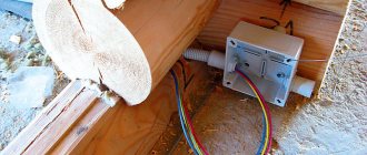
Open wiring in a private house
Installation of open electrical wiring
Installation of open electrical wiring is carried out in buildings made of wood, panels, panels and other flammable materials. When designing, you need to take into account that the distance of wiring from the ceiling should be at least 2 cm, and floor sockets - no more than 1 meter. When laying lines, it is prohibited to use nails, staples and screws to secure the cable directly to the load-bearing surface.
Regulatory documents establish the following installation options:
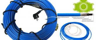
- flexible corrugated tubes;
- rigid round and rectangular plastic profiles;
- metal hoses with threaded connections;
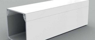
- polymer cable channels;
- hollow detachable platbands and baseboards;
- steel strings;
- ceramic insulators.
Since such structures look unaesthetic on the ceiling, there are several ways to disguise them. For this purpose, tension structures, suspension systems made of gypsum plasterboard, plastic panels and metal slats are used.
Useful tips Connection diagrams Principles of operation of devices Main concepts Meters from Energomer Precautions Incandescent lamps Video instructions for the master Testing with a multimeter
Pros and cons of external wiring
Therefore, the first and main advantage of external wiring in an apartment is the speed of its installation. For example, you can install exposed wiring in a one-room apartment with your own hands, without much experience, in a couple of days. A professional hired electrician can do it in five to six hours.
The second advantage is that for open wiring you do not need to groove the walls, make channels in them for laying wires and sockets for sockets, switches and junction boxes, and then, after installation, re-plaster, paint or wallpaper the walls.
The third plus is that open wiring is always available. You can repair the damaged area or add some new elements to the wiring at any time without much effort. For example, run another branch to a new lamp, install a new additional one, or move an old socket to another location. With hidden wiring, such a number will not work: you will have to drill into the walls.
But open wiring also has its disadvantages.
The first disadvantage is that exposed wiring is always visible, and it does not look harmonious in all interiors. Unless you are making an interior in country, retro, techno or steampunk style. In this case, exposed wiring can be a highlight.
The second disadvantage is that you must clearly take into account the technical standards of the room in which you are doing open wiring. For example, in the bathroom, kitchen and other rooms with high humidity, even for hidden wiring, you need to use additional wire protection and install devices (switches, sockets) with a protection class of at least IP-44, and for open wiring - at least IP-68. But they don’t always look beautiful and attractive.
RULES FOR EXTERNAL LAYING
External wiring includes electrical wiring laid along the external walls of buildings, under canopies and between buildings on supports.
The external cable is laid in both open and hidden ways, taking into account the following requirements:
- Location of the external cable in a place inaccessible to human touch or its fencing;
- Excerpts of the recommended PUE distance from open wiring areas to the ground and building structures (from 0.5 to 2.75 m);
- A ban on external cable laying on top of the roofs of residential and public buildings, with the exception of entry points and branches to them.
The latter are laid through walls using special insulating pipes. The requirements for laying external cables in pipes, ducts and flexible hoses are no different from the rules for protecting open wiring; steel protective casings are not used outside buildings.
In any case, the accumulation or accidental entry of moisture into the protective pipes is avoided at the input areas.
The need for a protective casing depends on the resistance of the cable insulation to ultraviolet radiation; wiring type VVGng-LS needs it, SIP and its analogues intended for outdoor use do not.
Good protection from UV is provided by HDPE corrugations or metal electrical boxes; when using PVC corrugations, this indicator is specified separately. Cables laid on external walls made of wood require special attention; regardless of the type of insulation, they are covered with non-flammable materials.
Chipping of façade walls and hiding the cable inside the channels followed by plastering is considered the optimal method in terms of safety and aesthetics. But in practice it is rarely implemented due to labor intensity and financial costs; in most cases, external wiring is laid openly.
Mandatory requirements for cable installation include its fixation; the fastening step depends on the diameter of the corrugation (if any) and is selected from the tables. Completely open wires are fixed in increments of no more than 500 mm in vertical sections, 350 in horizontal sections and 100 in bend sections.
* * *
2014-2020 All rights reserved. The site materials are for informational purposes only and cannot be used as guidelines or regulatory documents.
AND REINFORCED CONCRETE TRAYS
2.3.102.
For the manufacture of cable blocks, as well as for laying cables in pipes, it is allowed to use steel, cast iron, asbestos-cement, concrete, ceramic and similar pipes. When choosing material for blocks and pipes, you should take into account the level of groundwater and its aggressiveness, as well as the presence of stray currents. Oil-filled single-phase low-pressure cables must be laid only in asbestos-cement and other pipes made of non-magnetic material, and each phase must be laid in a separate pipe.
2.3.103. The permissible number of channels in blocks, the distances between them and their size must be taken in accordance with 1.3.20.
2.3.104. Each cable unit must have up to 15% redundant channels, but not less than one channel.
2.3.105. The depth of installation of cable blocks and pipes in the ground must be taken according to local conditions, but not be less than the distances given in 2.3.84, counting to the top cable. The depth of installation of cable blocks and pipes in closed areas and in the floors of industrial premises is not standardized.
2.3.106. Cable blocks must have a slope of at least 0.2% towards the wells. The same slope must be observed when laying pipes for cables.
2.3.107. When laying pipes for cable lines directly in the ground, the smallest clear distances between pipes and between them and other cables and structures should be taken as for cables laid without pipes (see 2.3.86).
When laying cable lines in pipes in the floor of a room, the distances between them are taken as for laying in the ground.
2.3.108. In places where the direction of the route of cable lines laid in blocks changes, and in places where cables and cable blocks pass into the ground, cable wells should be constructed to ensure convenient pulling of cables and their removal from the blocks. Such wells should also be constructed on straight sections of the route at a distance from one another determined by the maximum permissible tension of the cables. When the number of cables is up to 10 and the voltage is not higher than 35 kV, the transition of cables from blocks to the ground can be carried out without cable wells. In this case, the places where cables exit from the blocks must be sealed with waterproof material.
2.3.109. The transition of cable lines from blocks and pipes to buildings, tunnels, basements, etc. must be carried out in one of the following ways: by directly introducing blocks and pipes into them, by constructing wells or pits inside buildings or chambers near their outer walls.
Measures must be taken to prevent the penetration of water and small animals from trenches into buildings, tunnels, etc. through pipes or openings.
2.3.110. The channels of cable blocks, pipes, their outlets, as well as their connections must have a treated and cleaned surface to prevent mechanical damage to the cable sheaths during pulling. At cable exits from blocks to cable structures and chambers, measures must be taken to prevent damage to the sheaths from abrasion and cracking (use of elastic linings, compliance with the required bending radii, etc.).
2.3.111. If the groundwater level is high on the territory of the outdoor switchgear, preference should be given to above-ground methods of laying cables (in trays or boxes). Aboveground trays and slabs for their covering must be made of reinforced concrete. The trays must be laid on special concrete pads with a slope of at least 0.2% along the planned route in such a way as not to interfere with the flow of storm water. If there are openings in the bottoms of the above-ground gutters that allow for the release of storm water, there is no need to create a slope.
When using cable trays for laying cables, passage through the territory of the outdoor switchgear and access to the equipment of machines and mechanisms necessary for performing repair and maintenance work must be ensured. For this purpose, crossings over the trays must be arranged using reinforced concrete slabs, taking into account the load from passing traffic, while maintaining the location of the trays at the same level. When using cable trays, laying cables under roads and crossings in pipes, channels and trenches located below the trays is not allowed.
The cable exit from the trays to the control and protection cabinets must be carried out in pipes that are not buried in the ground. Laying cable jumpers within one open switchgear cell is allowed in a trench, and in this case the use of pipes to protect cables when connecting them to control and relay protection cabinets is not recommended. Cables must be protected from mechanical damage by other means (using an angle, channel, etc.).
EXTERNAL ELECTRICAL WIRING
In another way, external electrical wiring is called street wiring. It is laid outside houses, along the walls of structures and buildings, as well as between them on special structures or supports.
Such wiring is necessary to supply voltage to lighting lamps, alarm systems, CCTV cameras and utility rooms (garage, workshop, shed, sauna, bathhouse, swimming pool).
All this must be taken into account at the stage of construction of buildings and structures.
External electrical wiring in a country house is no less important than internal wiring. In addition to the need to provide sufficient lighting in the area, at any time you may need to connect a power tool (drill, grinder, lawn mower, pump) in the yard. Don’t drag the carriers across the entire house and property; when planning the power supply, it is better to mark out places for installing 2-3 sockets.
The most important difference between external electrical wiring is that it is exposed to atmospheric factors - rain, snow, wind, sun rays. Therefore, it must be reliably protected from precipitation, from mechanical influences and accidental human contact with live parts.
General requirements for electrical wiring.
These requirements apply equally to both apartments and private houses:
1. All boxes, sockets and switches must be located in such places that they are always easily accessible.
2. All connections and branches are made only in boxes.
3. It is prohibited to install sockets in wet rooms (bathroom, sauna, bathhouse).
4. Grounding and grounding conductors are connected only by welding.
5. Grounding of stationary plates is carried out by separate conductors.
According to the PUE (Electrical Installation Rules), the following are also regulated:
- standards for the number of sockets per room;
- the distances at which sockets and switches should be placed in relation to the floor and communications;
- norms for laying wires (vertical and horizontal sections).
2.5.215
The passage of overhead lines over buildings and structures is, as a rule, not allowed.
It is allowed to pass overhead lines over industrial buildings and structures of industrial enterprises of fire resistance degree I and II in accordance with building codes and rules for fire safety of buildings and structures with roofing made of non-combustible materials (for overhead lines 330-750 kV only over industrial buildings of power stations and substations). In this case, the vertical distance from the overhead line wires to the above buildings and structures with the greatest sag should be no less than those given in Table 2.5.22.
Metal roofs over which overhead lines pass must be grounded. The grounding resistance should be no more than that specified in Table 2.5.19.
For overhead lines of 330 kV and above, protection of personnel located inside production buildings of power plants and substations must be ensured from the influence of the electric field, and the metal roof must be grounded at at least two points.
Tips and ways to hide wires in the workplace
In a home office, to make it look neat, the laces coming from the computer and router also need to be removed. A stationery clip will allow you to “run” the cord, which gets tangled under your feet, under the surface of the table - from its very edge. The clip is easy to fix on a wall or shelf, and several of these parts make a kind of separators for the inputs of different charges. If possible, the wires hanging near the back of the table are simply covered with a textile curtain. Some of them can be configured into a mini-hammock - the “head” of an extension cord can easily fit there, along with chargers that would get in the way on the table.
Some companies produce special wire separators - two or more cords are neatly laid inside a wooden, plastic, rubber or metal structure. A cool store-bought option for holding wires, it looks like two wire electrical towers. Pockets made from plastic bottles and clothing pockets look funny - the product is hung on an outlet in the wall, the charger is turned on, and the phone itself and its cord lie quietly in the pocket.
Ideas on how to hide the cable from a TV or home theater
Cables, cords from TV, set-top boxes, speakers are neatly hidden behind the shelf on which the TV is placed. If you decide to hang the screen on the wall, the wire is hidden in a box matched to the color of the wallpaper, and under it is placed a climbing plant, the tendrils and branches of which are allowed to curl around the box.
Many designers suggest not hiding the wires, but simply decorating them with colored ribbons, for decorating an apartment in the pop art style, indoor plants (climbing ones are optimal) - for eco-style, hollow driftwood boxes, wooden panels, if we are talking about classic interiors .
When you have to hang a bracket for a heavy TV, the design of the first one is chosen so as to fit all the sockets there. Sometimes a box is mounted on the wall where the TV screen will be placed, in which the cords from the speakers, DVD player, and other electronics will be hidden.
Difficulties in dismantling wiring
To accurately dismantle old electrical wiring, you need to know the layout of the channels. Unfortunately, it is almost impossible to find such a scheme, which presents an undoubted difficulty for carrying out such work. In addition, electrical wiring could be laid not only in the walls. The ceiling and the junction of the side and top panels were also often used for these purposes.
Dismantling electrical wiring requires significant labor costs and a large list of tools and materials. If you are not ready for such work, it is better to immediately delegate its implementation to a qualified electrician, who will carry out the dismantling more quickly and with much better quality than you. If you still decide to do all the operations yourself, remember the important rules:
- Do not groove in load-bearing walls, especially in the horizontal direction. This can significantly weaken the structure of the entire building.
- Don't get carried away with gating. If possible, new electrical wiring should be installed in old, existing channels.
- If there are not enough channels, make additional grooves with a depth of no more than 10 mm using a hammer drill or wall chaser, and use dowels to secure the wires in them.
- Any finishing work can be carried out only after checking the serviceability of the newly laid electrical network.
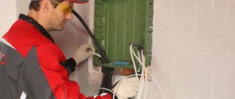
Carrying out installation work
Any electrical repair work requires opening the junction box. When checking the voltage, use a special indicator. If there is no voltage, this is evidence of incorrect connection or broken wires.
Before carrying out any electrical work, disconnect the plugs in the distribution panel. This will ensure safety and allow you to carry out any repair operations on the electrical route without the threat of electric shock.
Other fire and building codes must be taken into account:
- separation boxes, switches, meters and sockets must be installed in easily accessible places;
- GOST recommends installing sockets at a height of 60 cm, switches at a height of 90 cm;
- sockets cannot be installed near metal objects (pipes or radiators), the minimum distance from them should not be less than 0.5 m;
- the number of sockets in a living space is calculated based on the total area of the room - one socket per 6 m2, while the kitchen should not have less than 3 sockets;
- the bathroom is equipped with moisture-proof sockets;
- when choosing switches and sockets, it is better to choose products with a ceramic base and copper contacts;
- cables laid in a vertical position must retreat from window and door openings to a minimum “distance” of 100 mm.
It is necessary to say a few words about the geometry of laying electrical cables in the apartment.
All wires must be laid exclusively vertically. and horizon. lines, with cable turns strictly at an angle of 90. This arrangement will eliminate the risk of damage to electrical wiring when hanging pictures or other decorative elements.
Is it possible to do without gating?
Grilling is a long and complex process, during which a large amount of dust is generated.
And if during a major renovation this is not too much of a problem, then in other cases not all apartment owners are ready to put up with such inconveniences.
Therefore, the question remains relevant: how to change the wiring in a panel house without gating? Replacement of electrical wiring can be done in an open way, when the wires are laid directly along the walls. This method will not disrupt the design of your apartment, since the wires can be camouflaged with special skirting boards or covered with plasterboard panels.
After marking the walls, indicating the installation of sockets, switches and lamps to which electrical wiring must be laid, the wires are laid in the baseboards and attached to the walls. A mandatory step in this method is to check the insulation resistance, and only after obtaining satisfactory results can voltage be applied.
Open wiring has its disadvantages:
- increased costs for the purchase of fastening and other materials;
- a slight reduction in the living space of the apartment due to the use of plasterboard panels.
Partial replacement of electrical wiring
The situation does not always require a complete replacement of the wiring. Often you can get by with repairing a separate section of the electrical network. Having determined the location of the wire deformation and de-energized the electrical wiring, you can begin repairs.
The faulty socket is removed from the socket box and the wires supplying it are disconnected.
Installation procedure
Preparatory operations
Proper wiring – trouble-free electrics in the house
Before you begin installing electrical wiring on your own, you should carry out a number of preparatory operations, namely:
- Clear the walls of all unnecessary objects and things;
- Mark the route of laying and installation locations of junction boxes;
- Mark the installation points for sockets, switches and lighting fixtures.
Additional Information. Regardless of the method of laying metal pipes, installation products (sockets, boxes and switches) are either recessed into the thickness of the wall or mounted on special socket boxes.
The appearance of these products can be seen in the figure below.
Classic wooden socket box
The marking of the future route for electrical wiring must be carried out in strict accordance with the requirements of the PUE. The latter prescribe when laying wires to make as few changes in its direction as possible.
In cases where the design features of the walls do not allow for a continuous laying line, additional distribution boxes must be installed at certain points.
Installation requirements
Before you do the electrical wiring yourself, in accordance with current regulations, first of all, you need to decide on the installation locations of the junction boxes. In addition, the PUE stipulates the following important points for the upcoming work:
- When installing boxes, they are not allowed to be covered with any elements of decorative wall decoration, which would significantly complicate access to them when repairs or maintenance are necessary;
- When burying pipes into the body of wood (in accordance with the requirements of state standards), the strength properties of walls and other structural elements of buildings must not be violated;
- The cross-sections of pipes (ducts) used during installation and the thickness of their walls must correspond to the characteristics of the selected cable;
- In a situation where the decision is made to hide the cable in a pipe or box, you will need to ensure that it does not occupy more than 40% of the volume of their internal space and is easily laid along the entire length of the wiring;
- When placing several cables in this space, the volume they occupy should also not exceed 40 percent;
- Before laying any cable, it is recommended to double-check its insulation resistance.
Taking into account this indicator is necessary to fully ensure that its characteristics comply with GOST requirements (since during storage, transportation and preparation for installation, the possibility of damage to the insulation cannot be excluded).
Placement of installation products
In the case where it is decided not to use special socket boxes during installation, and a hidden wiring socket is used, sockets with a diameter slightly larger than that of the prepared product are drilled at the installation sites.
Note! For these purposes, it is most convenient to use an electric drill with a special attachment called a “crown” (see photo below).
Crown type attachment
Metal boxes are first inserted into the sockets drilled in this way, which serve to place the installation products themselves. When installing them, it is necessary to comply with the requirements of regulations that require mandatory compliance with construction technologies. They relate to the production of work on connecting metal products into a single system, which requires a welding unit. Combining these system elements into a single whole will make it possible to subsequently organize reliable grounding of the electrical network.
If there is continuity of the metal connection, such protection is displayed on the electrical panel, from the central grounding bus of which it can be connected to a grounding device prepared near the house. The appearance of the memory can be seen in the figure below.
Appearance of a typical memory
When operating an external grounding loop, it will be necessary to carefully monitor the condition of all elements included in the structure, preventing corrosion of electrically conductive busbars and conductors.
Installation of sockets and switches
The above description of the procedure for organizing installation work concerns the case when the owner of a private wooden house has his own welding machine. However, in suburban conditions, not all users have a device that allows them to connect pipes and installation boxes by welding.
In the absence of a special unit, the following methods are allowed for arranging reliable connections between all metal parts of the system:
- In the case when the supply to two-socket sockets and separate 2-contact switches is carried out through copper pipes, their open edges, connected to the installation boxes, must be carefully flared;
- When using steel pipe products, a nut or bolt connection can be used instead of welding to securely fix them in metal walls (photo below);
Connection of pipes and boxes
- The figure shows that threads are cut on the pipes, after which the housings of installation or distribution boxes are screwed onto them, which are subsequently fixed in a given position.
To avoid possible deformations and corrosive destruction, the place of their joint is securely fixed using a nut of the appropriate size, and then lubricated with a protective compound.
Installation boxes (they are also called “technological”), as well as all other installation products, according to the provisions of the PUE, must comply with class IP-54 in terms of their protection from external destructive influences. This class for electrical installation equipment guarantees reliable protection of all installation products from the penetration of moisture and dust into their internal spaces.
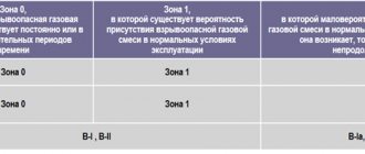
Section 7. Electrical equipment of special installations
Chapter 7.1. Electrical installations of residential, public, administrative and domestic buildings Scope. Definitions General requirements. Electrical supply Input devices, distribution boards, distribution points, group panels Electrical wiring and cable lines Internal electrical equipment Electricity metering Protective safety measures Chapter 7.2. Electrical installations of entertainment enterprises, clubs and sports facilities Scope. Definitions General requirements. Power supply Electric lighting Power electrical equipment Laying cables and wires Protective safety measures Chapter 7.3. Electrical installations in explosive zones Scope of application Definitions Classification of explosive mixtures according to GOST 12.1.011-78 Classification and marking of explosion-proof electrical equipment according to GOST 12.2.020-76* Classification of explosive zones Selection of electrical equipment for explosive zones. General requirements Electrical machines Electrical apparatus and instruments Electrical lifting mechanisms Electrical lamps Switchgear, transformer and converter substations Electrical wiring, conductors and cable lines Grounding and grounding Lightning protection and protection against static electricity Appendix 1 Appendix 2 Appendix 3 Chapter 7.4. Electrical installations in fire hazardous areas Scope Definitions. General requirements Electrical machines Electrical apparatus and instruments Electrical lifting mechanisms Switchgear, transformer and converter substations Electrical lamps Electrical wiring, conductors, overhead and cable lines Chapter 7.5. Electrothermal installations Preface Scope of application Definitions General requirements Installations of direct, indirect and resistance arc furnaces Installations of induction and dielectric heating Installations of direct and indirect resistance furnaces Electron beam installations Ion and laser installations Chapter 7.6. Electric welding installations Preface Scope of application Definitions General requirements Requirements for premises for welding installations and welding stations Installations for electric welding (cutting, surfacing) by fusion Installations for electric welding using pressure Chapter 7.7. Peat electrical installations Scope. definitions Power supply Protection Substations Overhead power lines Cable lines Electric motors, switching devices Grounding Acceptance of electrical installations for operation Chapter 7.10. Electrolysis and electroplating plants Preface Scope Definitions. Composition of installations General requirements Installations for electrolysis of water and aqueous solutions Electrolysis installations for hydrogen production (hydrogen stations) Electrolysis installations for chlorine production Magnesium electrolysis installations Aluminum electrolysis installations Electrolytic refining installations for aluminum Electrolysis installations for ferroalloy production Electrolysis installations for nickel-cobalt production Electrolysis installations for copper Electroplating installations
Hiding wires in the wall
The most popular option is when the cable is hidden directly in the wall - the so-called “hidden wiring”. To do this, appropriate recesses are cut out in it, where electrical wires are placed, and the recesses are covered. It turns out dusty and takes quite a long time, but if the work is done efficiently, the dangerous parts are securely hidden - it will not be possible to see, much less damage them, without compromising the integrity of the wall.
Into a concrete/brick wall
It is advisable to install electrical wiring at the renovation stage, preferably during the planning of the premises. As long as the walls are bare, there is no decor on them, damage will be minimal
It is important to know that “pulling” the cable diagonally, which is sometimes done in order to save money, is unacceptable - hidden electrical wiring is laid only vertically-horizontally. This will allow you to quickly repair it in the event of an accident, minimizing the risk of electrical damage. The minimum distance from the ceiling to hidden wires is 15-18 cm
The minimum distance from the ceiling to hidden wires is 15-18 cm.
To begin with, a wiring diagram is drawn up, marking is done using the construction or laser method. To make grooves, take a hammer drill, grinder or wall chaser. The parts are attached to the brick or concrete wall with dowel clamps. After the cable is laid, the grooves are primed, covered with plaster, and the wall is leveled.
Into a plasterboard wall
Installing electrical wiring under drywall is much easier than installing into concrete. Here you should also lay the cable along a clear route so that multiple screws do not damage it. To begin with, a frame is “assembled” from aluminum profiles and drywall. The cord must be laid in a special corrugated pipe, which has a fire safety certificate. When there is already a plasterboard wall and it is necessary to lay a cable in it, then a layout diagram of the electrical equipment is drawn up. The cords here are pulled horizontally, vertically, including through holes in the metal profiles supporting the drywall.