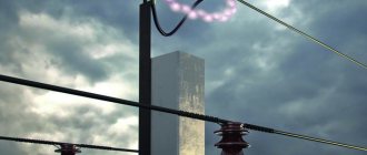
The specificity of the problem of lightning protection on overhead lines (overhead lines with protected wires) is that if the wires in the insulation are not protected by anything, then during a lightning overvoltage and the insulator overlaps, an arc is formed, which simply has nowhere to move along the wire.
Accordingly, it burns at the point of insulation breakdown until the protection at the substation is triggered and the overhead line emergency shutdown. Since the protection in this case does not work immediately, the following consequences may occur:
- damage to SIP-3 insulation
- destruction of the insulator itself at the VLZ
- burnout and broken wire
It is the burnout of the wire that is the main condition for the need to use lightning protection devices for SIP-3.
Arc horns
Initially, a system of arc protection “horns” was widely used. When an arc and a single-phase fault were artificially converted into a two-phase short circuit with a guaranteed shutdown of the power line.
However, this system has significant disadvantages:
- it does not protect the insulation from overvoltage
- does not prevent line disconnection, but rather contributes to it
Meanwhile, for lines with an isolated neutral, a single-phase fault is not an emergency mode requiring immediate shutdown.
In addition, the “horns” periodically burn and require replacement.
And when the overhead line passes through plantings and forest clearings, interphase short circuits are possible due to contact with branches.
Therefore, to protect overhead power lines of medium voltage 6-20 kV from lightning overvoltages, special devices began to be used - long spark gaps of the loop type RDIP.
Technical characteristics of gas arresters
Each gas arrester has specific electrical properties and technical characteristics.
- Rated pulse discharge current . The technical requirements for the arrester determine its ability to withstand a certain value of pulse current. Deviation from the norm has acceptable limits determined by the requirements. The nominal current value is always specified in the technical specification of the specific device.
- Capacitance and insulation resistance . These parameters reach, respectively, over 10 gOhm and less than 1 pF, which makes such devices literally indispensable when used in a particular network.
- Static response voltage . This parameter determines the type of arrester installed in the protective device. Its value is equal to the voltage sufficient to ignite the spark gap, provided that the voltage increases slowly.
- Dynamic response voltage . This value is a kind of limit when a rapid increase in voltage occurs, at which the gas spark gap is triggered.
Long spark gaps
These devices must be installed along the entire length of the overhead line, at the approaches to the substation and cable inserts. This makes it possible to eliminate the overlap of insulation on the line and negate the negative consequences of induced lightning overvoltages.
This should not happen:
- emergency power line outages
- destruction of insulators
- burnt wire
- plus protection of substation equipment and cable inserts is provided
Long spark gaps RDIP or PDR-10 (from Niled) must be installed on a protected section of the route, one for each support with cyclic phase rotation.
That is:
- on support No. 1 we connect the arrester to the FA
- on support No. 2 on fV
- on support No. 3 on FS
It is not entirely advisable to place two RDIP arresters simultaneously on adjacent phases of an intermediate support with pin insulation, even if space permits. Otherwise, a single-phase circuit may turn into a two-phase circuit with subsequent emergency shutdown of the overhead line.
General structure and principle of operation
High-frequency equipment is protected not only by lightning rods, but also by high-voltage arresters. Each of them consists of two main parts - electrodes and a device for extinguishing the arc.
One of the electrodes is installed on the protected circuit, and grounding is connected to the other. A space is formed between them, known as the spark gap. When the voltage reaches a certain value, a breakdown of the spark gap between the two electrodes occurs. Due to this, the overvoltage is removed from the protected section of the circuit. The main technical requirement for the arrester is a certain level of guaranteed electrical strength under industrial frequency conditions. That is, during normal operation of the network, the arrester should not break through.
After a breakdown, the arc extinguishing device comes into action. Under the influence of the pulse, the ionization of the spark gap increases, as a result of which the phase voltage operating in normal mode breaks through. It leads to a short circuit and activation of protective devices in this area. The main task of the arc extinguishing device is precisely to eliminate the short circuit as quickly as possible, before the protective equipment is activated.
Installation of RDIP on 6-10 kV overhead lines with pin insulators
Secure the arrester with a clamp to the insulator pin.
To set the gap between the SIP-3 wire and the arrester, you can manually change the bend of the loop. Next, a universal or biting clamp is mounted. It is placed on the inside of the loop.
The air gap is adjustable. Its value for VLZ-6-10kv:
- 40mm from SIP wire
- 20mm from universal clamp
Three-electrode arrester with thermal relay manufactured by CITEL
A more common method when it comes to telecommunications applications is a thermal arrester. These arresters use durable electrodes that can withstand repeated actuation. A thermal relay is switched on in parallel with the arrester. When an arc discharge occurs, the chamber heats up and the thermal relay is activated, shunting the arrester. The voltage across the spark gap drops to zero and the arc discharge stops. After the thermal relay cools down, its contacts open and the spark gap goes into a resting state. Dischargers with thermal relays can withstand up to 10 operations.
Installation on a tension garland
First of all, loosen the fastening of the arrester arms. After which the RDIP is separated from the fastener.
The bracket rotates 180 degrees and fits only on one shoulder.
This is done so that the arrester loop can be threaded through the SIP wire without breaking it. Both arms can now be tightened again.
Attach the mounting bracket to the top earring of the garland and set the air gap. It is measured between the central electrode on the arrester and the nearest metal part of the fittings.
If it is not possible to secure the RDIP to the garland, then use suitable fastenings for traverses and slopes.
Types of fasteners and distances for the loop arrester on VLZ-6-10kv:
Corner anchor supportIncreased corner intermediateCorner intermediateDouble chain corner intermediateDouble chain anchorCorner anchorSingle chain corner intermediate
How to distinguish an original RDIP-10 arrester from a counterfeit one?
The main differences are as follows.
There is no marking on the PIGR shell itself; The design of the bracket is different - the counterfeit one is welded, ours is stamped; end cap (aluminum cap at the end of the product) - ours is in the form of a glass, one-piece, obtained by extrusion, while the counterfeit is made of an aluminum pipe and capped on one side with an aluminum stopper; the outer surface of the PIGR is heavily worn, a breakdown of the PIGR when checking the electrical strength of the insulation; spring electrodes on original arresters and flat electrodes on counterfeit ones; on counterfeit RDIP nameplates there are “Streamer”, but without the batch number and product number; As a rule, in invoices and accompanying documents, counterfeit arresters are marked using non-Roman, Arabic 4s, i.e. RDIP-10-4-UHL1.
Disadvantages of RDIP
However, a long period of operation shows that this type of protection does not always fully fulfill its functions. On some overhead lines, the number of single-phase short circuits may even increase.
In addition, tests confirm that RDIP cannot always protect the insulation on adjacent supports. That is, on the next two, where it is not installed in this phase. Here, much will depend on the brand of insulator, the distance between the supports and the level of overvoltage.
ShF-20 can even block insulators.
Here's a visual test in the lab:
Disposable and self-restoring arresters
A disposable spark gap will not be able to protect insulation and equipment from repeated lightning. After completing its action, it represents a jumper with a resistance close to zero. In power supply networks, such a jumper triggers a protection that cuts off the power supply. Communication in telecommunication networks is interrupted, which triggers an alarm. After receiving a signal about a power outage or interruption of communication, a specialist comes to the site to replace the disposable arrester.
The simplest option for implementing a disposable spark gap is electrodes inside the chamber, made of metal that melts under high temperature. A more complex option is a jumper attached to the chamber wall with a drop of easily melting metal. During an arc discharge, this drop melts and a jumper connects the electrodes. You've probably already guessed that a disposable spark gap is not the best solution for protecting electrical lines and devices.
A self-healing spark gap is capable of returning to its resting state a limited number of times. Sometimes such a surge arrester is used in conjunction with a trip counter, which allows one to estimate the lightning load and the expected service life of the device.
Arresters RMK-20, MCR
Therefore, recently, along with loop-type devices, arresters with the RMK-20 or MCR (Niled) multi-chamber system have become widely used.
It is more compact and easier to install. In terms of application and installation scheme, MCR (RMK-20) is similar to traditional long-spark ones. That is, it is also installed on each support with alternating phases.
What does RMK-20 consist of:
- multi-chamber system - discharge element
- bracket for attaching an insulator or traverse to the reinforcement
- universal wire clamp
It can also be supplemented with an operation indicator.
The design of the bracket is universal and allows you to mount RMK-20 on intermediate and anchor supports SV-105,110,164 with several types of insulation.
Arc extinction methods
Ensuring that the arc is extinguished in a given period of time can be achieved by using a special gas that suppresses the electric arc when the current is below a threshold value. But in practice, this method is rarely used; the disadvantage of such arresters is the low stability of the service life. That is, the number of possible operations can only be determined approximately in advance.
Preparation for installation
Before installation, be sure to carry out an external inspection. The discharge element must be free of cracks, cuts, mechanical dents, etc. Try to bend the element using light force. It should be sufficiently elastic and immediately restore its original shape.
If the kit includes response indicators, check the integrity of the opaque glass bulb.
Initially, the arrester is supplied disassembled. Therefore, it must be assembled into a single structure. Use a bolt with nuts and washers to connect the bracket and the multi-chamber system.
How does the arrester work?
Arresters are needed to protect overhead power lines (OHT) from lightning effects, including the consequences of direct lightning strikes. Overhead lines are long electrical circuits consisting of wires and auxiliary devices that transmit and distribute electricity. On any long line there are several areas that require increased attention. For example, if the line passes through a hill, a water barrier, an area of abnormal thunderstorm activity, or is located on the approach to substations. Installation of 10 kV arresters produced by NPO Streamer JSC ensures the limitation of lightning overvoltages on the line, thereby protecting the equipment of electrical networks and installations from emergency shutdowns and damage after lightning strikes. Every time lightning impacts power equipment, resources are depleted and the equipment ages significantly. Thus, economic losses from the impact of lightning on energy systems are reduced. Practice shows that the costs of lightning protection measures are several times lower than the costs of eliminating the consequences of lightning strikes.
Installation of RMK-20 on a pin insulator
The arrester is mounted directly on the pin under the insulator by its fastening. Moreover, the bracket should initially be slightly loosened to be able to adjust its position.
The angle of displacement of the arrester relative to the wire axis should be within 30 degrees.
The distance from the bracket to the lower skirt of the insulator is also adjustable - 30mm. The best way to do this is using a template.
After adjustment, the bracket bolts can be tightened. Tightening force 25 Nm.
There must be an air gap of a fixed size between the SIP-3 wire and the RMK-20 tip. To do this, a universal clamp is mounted on the wire.
For VLZ with SIP-3 wires, the clamp has a piercing spike.
Important note: if the wire is fixed to the insulator with a spiral binding, then the spike must pass between its turns without damaging the binding itself!
The universal clamp is tightened in a horizontal position.
Next, to adjust the air gap, slightly unscrew the bolt fastening and move the arrester in the desired direction. I can simply set the size of the air gap between the end spherical electrode and the clamp on SIP-3 according to the template.
This gap must be within the following limits:
- for VL-6-10kv - 40-60mm
- for overhead line-20kv - 50-70mm
Please note that bending the arrester without loosening its bracket is prohibited. Otherwise, you may damage the internal reinforcing element.
Installation of supports for VLZ-10kv
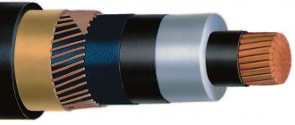
The SIP-3 wire can be mounted both on new supports and on existing ones, instead of bare AC-50-70-95-120 wires. Naturally, with the replacement of all load-bearing, fastening fittings and insulation. Replacing an old 10 kV overhead line with a new overhead line with SIP-3 wires is called reconstruction.
Both reconstruction and new construction must be carried out according to the project.
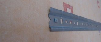
Most often, the installation of a new overhead line begins with the installation of anchor supports. Even before the anchor support post is raised, the required number of traverses are secured to it on the ground.
To prevent corrosion, and also because the line must be maintenance-free, it is necessary to use galvanized crossbars. Otherwise, in a few years you will have to re-climb each support and repaint the faded cross-arms to protect them from rust.
The traverse is immediately grounded. This is done by connecting a die clamp and a steel rod with a diameter of at least 10 mm (section 78.5 mm2) to the grounding outlet at the top of the support.
On reinforced concrete supports, both welded and bolted connections are allowed. On wood, it is recommended to use dies first.
On multi-post anchor supports, the number of grounding descents must be at least two. As such, you can use elements of longitudinal reinforcement of reinforced concrete racks SV-105-110.
All metal structures here (the strut fastening, the traverse itself) are grounded from above, through the grounding outlet. There is no need to make a separate descent made with a rod or strip, directly along the body of the support to the ground.
It is advisable not to screw the insulators onto the traverse onto the ground until the support is installed, in order to avoid accidental damage and damage during installation with special equipment. A partially equipped rack is installed at the desired point using a truck crane or a drill crane machine.
Then one or two struts are installed. Their number depends on the route layout and is determined by the project.
The support must be buried at least 2.3-2.5 meters. After this, intermediate supports are installed.
Installation of arrester on suspended insulation PS-70
The arrester is fixed on top of the suspension insulator earring.
The angle of displacement of the arrester element from the wire axis is 30 degrees.
Having set the angle, the bracket is tightened. Next, adjust the gaps. The horizontal distance between the skirt of the upper insulator and the arrester electrode should be approximately 30mm. Once you have it out, tighten all the nuts.
The universal clamp is installed here as close as possible, close to the supporting clamp of the garland.
When installing the operation indicator, ensure its vertical position. At the same time, it should be located under the spherical electrode of the spark gap.
conclusions
Spark gaps are used as inexpensive, reliable devices that can withstand heavy loads. In telecommunications applications, the use of varistors is limited due to their high capacitance. At the same time, the feasibility of their use largely depends on economics. The valve arrester is an expensive device that requires replacement every 20 operations. The cost difference between solid-state and valve-type arresters is completely offset by higher operating costs, so a solid-state arrester is preferable.
Are imported arresters that good?
Over the years, we, JSC EMSOTECH, have purchased thousands of arresters of various types and used them in complex noise protection devices. We have accumulated some experience working with imported arresters. It led to the fact that the specialists of JSC EMSOTECH began to treat with caution the characteristics of the arresters declared by their manufacturers. We purchased and tested in the laboratory the arresters of most foreign companies that have sales networks in Russia and conduct active advertising on the Internet. It turned out that, despite the presence of certificates confirming the compliance of arresters with the requirements of the standards, the majority of tested arresters have many times higher characteristics.
Based on the research results, we were forced to abandon the import of high-current arresters and develop an original arrester design for our products (we received a patent for the invention), which best satisfies the requirements of lightning protection.
The results of comparative tests of arresters are given in the report.
There is no need to comment on the difference in the condition of the imported arresters and the arrester of ZAO EMSOTECH after testing. The test results reflect one of the main principles of the Soviet design school: “the reserve is not enough.” Therefore, the service life of our arresters is equivalent to the service life of the electrical equipment of the protected object. Western companies have a different approach: to design protection with a limited service life, since periodic diagnostics and subsequent replacement of arresters brings significant income.
Lightning protection arresters RGZN and complex lightning protection devices based on them
Our new products are low-voltage lightning arresters (LLV) and complex lightning protection devices based on them. Designed to protect low-voltage inputs into buildings, protect low-voltage windings of transformer substations, protect autonomous power sources (diesel generators, etc.), protect cables from insulation breakdown and protect other low-voltage equipment from lightning and switching overvoltages, lightning discharge currents. The arresters are protected by a RF patent for invention.
The article was prepared by specialists from JSC EMSOTECH and posted on the website with their kind permission.
It is possible to protect yourself from lightning without arresters, but it is difficult and expensive.
This is a mandatory element of the lightning protection system, so we will consider the arresters in more detail. Low-voltage, high-current spark gaps can quickly short-circuit a lightning-struck power line to ground and create a low-resistance path for lightning current. It is important to choose the right arrester, its installation location and installation method.
Foreign manufacturers of arresters are actively working in the domestic market, offering thousands of types of arresters, providing detailed catalogs and recommendations for selection. However, using its own example, EMSOTECH JSC was convinced that when choosing arresters one should be guided by the well-known saying: “it was smooth on paper, but they forgot about the ravines.”
Are imported arresters that good?
Over the years, we, JSC EMSOTECH, have purchased thousands of arresters of various types and used them in complex noise protection devices. We have accumulated some experience working with imported arresters. It led to the fact that the specialists of JSC EMSOTECH began to treat with caution the characteristics of the arresters declared by their manufacturers. We purchased and tested in the laboratory the arresters of most foreign companies that have sales networks in Russia and conduct active advertising on the Internet. It turned out that, despite the presence of certificates confirming the compliance of arresters with the requirements of the standards, the majority of tested arresters have many times higher characteristics.
Based on the research results, we were forced to abandon the import of high-current arresters and develop an original arrester design for our products (we received a patent for the invention), which best satisfies the requirements of lightning protection.
- The results of comparative tests of arresters are given in the report (Adobe PDF format).
There is no need to comment on the difference in the condition of the imported arresters and the arrester of ZAO EMSOTECH after testing. The test results reflect one of the main principles of the Soviet design school: “the reserve is not enough.” Therefore, we provide guarantees for our arresters that are equivalent to the service life of the electrical equipment of the protected facility. Western companies have a different approach: to design protection with a limited service life, since periodic diagnostics and subsequent replacement of arresters brings significant income.
Why are the characteristics of imported arresters overestimated?
To suspect the world's leading companies of jointly inflating the characteristics of arresters for the sake of advertising would be a manifestation of disrespect for competitors; such a position is initially incorrect. Imported arresters are destroyed by pulsed influences for a different reason.
Few specialists in the field of lightning protection are aware of the disagreements between domestic and foreign scientific schools of lightning studies regarding lightning protection testing methods, based primarily on the possibility of technical implementation of lightning discharge simulators.
When developing lightning discharge simulators, the domestic scientific school proceeds from the fact that a lightning discharge is initiated by an equivalent current source that has a high internal resistance. The lightning current source during testing is modeled by a capacitive storage device, which allows for a large pulse power to be delivered to the element under test in a short period of time. When charging the capacitive storage device, a charge Q=CU (Ac) is transferred through a high-voltage rectifier, corresponding to the simulated phase of the lightning discharge; charge Q, when the capacitive storage device is discharged, is transferred through the forming circuits to the spark gap under test.
Manufacturers of imported arresters test them on their simulators according to the IEC 62305-1-2006 standard. However, in such a simulator, the charge Q flowing through the spark gap is calculated theoretically and turns out to be tens of times greater than the initial charge of the capacitive storage device. The internal resistance of such a simulator turns out to be very low (and that of lightning is high), therefore, depending on the type of load of the simulator, the energy test regime is disrupted, as a result of which energy is supplied to the arrester much less than that which occurs during a lightning discharge. As a result, the testing conditions for arresters on IEC simulators are much milder than on a simulator with direct discharge of a capacitive storage device.
ZAO EMSOTECH has both types of simulators in its laboratory. On the IEC simulator, imported arresters are tested and their experimental characteristics basically correspond to the passport ones. However, when tested on a simulator with direct discharge of a capacitive storage device, at the same peak current values, all tested imported arresters were destroyed.
Misconceptions about high-current arresters.
Why can’t you believe the advertising claims of foreign companies?
- 1. Are arresters with a low response threshold, down to values less than 1 kV, good?
What causes the need to use controlled arresters with a low response threshold (usually 0.9...1.5 kV)? The main scheme for using arresters in lightning protection circuits for electronic equipment is two-stage. The first stage is a spark gap, the second is a varistor, the selectivity of their operation is ensured by an isolating choke or a piece of cable.
In the circuit, the arrester is triggered when an overvoltage occurs and diverts the lightning discharge current to the ground, the varistor limits the overvoltage pulse to a safe level until the arrester breaks down, and the choke for a short time prevents the varistor from shunting the overvoltage and thereby ensures the operation of the arrester. If the varistor limits the overvoltage to 1 kV, and the arrester operates at 4 kV, then the inductance of the inductor must be such that a pulse voltage drop of at least 3 kV occurs across it. If the overvoltage and current increase slowly, you have to increase the inductance of the inductor, make it larger and more expensive. Dischargers are produced mainly by “packaging companies,” that is, companies specializing in the production of plastic cases and packaging of various devices in them. An inductor with large inductance, rated current and pulse current is difficult to package in a plastic case for DIN rail mounting. The design idea of Western arrester manufacturers came up with the idea of using controlled arresters, the operating voltage of which would be lower than the limiting voltage of the varistors, and then the varistor and the arrester would operate on their own, without the use of a choke. However, “every coin has a flip side.”
Lightning impulse overvoltages with an amplitude of up to 10...30 kV, during which conventional uncontrolled arresters with a breakdown voltage of 4 kV are triggered, occur several times a year. The same number of times short circuits will occur in the electrical installation due to the operation of arresters.
Switching pulse overvoltages with an amplitude of units of kV occur much more often. In power supply networks of industrial enterprises, switching overvoltages with an amplitude of more than 1 kV occur daily, sometimes every time the equipment is turned on and off. Accordingly, the probability of operation of controlled arresters, for example, with a breakdown voltage of 0.9 kV, increases significantly. Each triggering of the arrester causes a short circuit in the power supply network. The use of controlled arresters with low response thresholds leads to an increase in the number of voltage dips, accompanying overvoltages when voltage is restored, and an increase in the number of disconnections of consumer circuits due to the operation of overcurrent protection of electrical installations.
- 2. Can arresters extinguish arc current as well as circuit breakers and fuses?
Fuses or circuit breakers are initially designed as current-limiting protection devices, which, due to their design features, strive to disconnect the emergency circuit as quickly as possible.
For short circuits with maximum frequency, they switch off the short circuit current in less than 10 ms. In terms of external features of the system of electrodes that form an arc of accompanying current, a lightning arrester is similar to a circuit breaker, but the physics of the phenomena on the electrodes is radically different. For example, the arrester may have horn-shaped electrodes shaped like the contacts in a circuit breaker, and may have an arc suppression grid similar to that found in a circuit breaker. However, in order to limit the short-circuit current, the contacts in the circuit breaker, under the action of a spring mechanism, quickly diverge over long distances, the arc is stretched mechanically and, by the action of electromagnetic forces, is forced into the arc-extinguishing grid, in which, by definition, it goes out. In the arrester everything is different; its design does not allow the arc to break instantly:
- The electrodes are motionless, so the arc is not mechanically stretched, and the initial interelectrode gap (about 1 mm) can be closed either by overvoltage when the arc breaks, or by a cloud of ionized plasma. Because of this, the process of extinguishing the arc may take a long time.
- In a spark gap, electromagnetic forces may not contribute to blowing the arc out of the discharge gap, but act in the opposite direction, blowing the arc into a small gap intended not to extinguish the arc, but to form a spark discharge. We had the opportunity to verify this using unsuccessful designs of arresters from well-known manufacturers.
- The electromagnetic forces acting on the accompanying current arc are very large when a large pulsed discharge current is superimposed on the accompanying current. The pulsed current blows an arc from a narrow gap onto the horns with a large interelectrode gap; the long arc of the accompanying current cools more intensely and is extinguished faster. At low pulse currents, the arc of the accompanying current literally “sticks” to the electrodes of the spark gap and the relatively weak accompanying current is not enough to accelerate the arc to those speeds at which it goes out due to cooling by the oncoming air flow.
- According to GOST R 51992-2002, in the tested spark gap, the extinguishing time of the accompanying current is not controlled, as long as “the through current is self-extinguishing.” The self-extinguishing of the accompanying current is checked only at its maximum value, and the accompanying current is extinguished worst of all at low current values, when the forces drawing the arc into the arc-extinguishing grid are small. The main requirement of the standard is that during such tests the spark gap does not have mechanical damage and that during the cooling interval of the spark gap (25...30 min.) “thermal stability is achieved”.
- One of the components of a lightning discharge with a current of hundreds of amperes has the form of a unipolar pulse with a duration of up to 0.5 s. This is a direct current that is extinguished very poorly; it does not allow the arc of the accompanying current with a frequency of 50 Hz to be extinguished when crossing zero.
Therefore, the arrester is not at all obliged to extinguish the arc with a current-limiting effect. The arrester can extinguish the arc, for example, in 5 seconds, and it will comply with the standard, since it has not collapsed or overheated. At the same time, at the protected facility, due to multiple (during the thunderstorm season) short circuits and associated disruptions in the operation of electrical installations, several pieces of equipment will fail.
The designer should know that the arc extinguishing system in the arrester can be of very high quality and designed for a large accompanying current, but it cannot be completely relied upon. The primary task for the arrester is to divert the lightning current to the ground, but arc arresters do not extinguish the arc well.
- 3. Is it possible to replace spark gaps with “varistor gaps”?
“Varistor arresters,” despite their trade name, by nature remain the same varistors, but packaged in modules that sometimes resemble spark gap housings. ZAO EMSOTECH is one of the few Russian enterprises that have tested “varistor arresters”. We can say that “varistor arresters” do not have any outstanding characteristics (except for price) in comparison with conventional modular (block) varistors, and an attempt to replace lightning arresters with them is obviously doomed to failure.
- 4. Is it true that the best arresters are those with carbon electrodes?
Specialists in the field of development of high-current arresters for lightning protection of power supply networks know that the worst material for such arresters is coal.
It's all about the physics of phenomena on electrodes. In order for the arrester to quickly respond to the occurrence of an overvoltage and close the lightning-damaged circuit to the ground, the arrester must have as short a response delay as possible after a voltage sufficient to break down the interelectrode gap appears on its electrodes. For the rapid formation of an electron avalanche and the initial arc current, many electrons are needed, which are extracted by the electric field from the electrode material. Light metals have low electron work function values, meaning it is easy for the field to extract electrons from these materials. Coal has a high electron work function, that is, it is difficult for the field to extract electrons from it, the required concentration takes longer to form, so the response delay time is long. As a result, the surge arrester may operate after the electronics have been affected by the overvoltage.
After the arrester is triggered by an overvoltage, an accompanying current of 50 Hz begins to flow through it; the arrester must extinguish it. There is a concept of a critical value of the arc current, at which the heated bases of the arc are instantly cooled (in 1 μs). The bases of the arc behind this transition can become almost instantly “cold”, not emitting thermal emission electrons from their surface. When the arc current decreases below critical values, the strength of the electrical gap is restored abruptly when the current passes through zero. The high critical effective current value (for a frequency of 50 Hz) for silver is 210 A and copper is 165 A, and the lowest critical current value for coal is 2 A. Therefore, the contacts of low voltage protective devices are made of silver or copper, and therefore the arc can be extinguished on carbon electrodes is much more difficult than on metal electrodes. If on copper electrodes the arc from a current source with a rated voltage of 220 V goes out after two breaks, then for coal they need much more, which is why carbon arresters are made multi-gap.
The history of electrical engineering is known for the “Yablochkov candle” in which an alternating current arc burned without dying out between parallel rod carbon electrodes. This is a good illustration of the "arc-quenching properties" of carbon electrodes.
The choice of carbon for electrodes is justified only from the point of view of the profitability of their manufacture. The production of such electrodes is more technologically advanced than metal ones and is easier to organize from scratch.
- 5. Is it possible to use arresters with a pulse current of tens of kA in cabinets with fuses for a current of tens of amperes?
Let's look at the product catalog of a well-known company: the DB 1 255 N arrester can pass a lightning current of 50 kA (10/350 µs), and its ability to limit the accompanying current is so good that the arrester does not trigger a 32 A fuse. is not capable of passing a lightning current of 50 kA, as we have already said (the filling of the arrester has melted). We open the recommendations for the use of products from the same company, we read: a 32 A fuse explodes at a current of 15 kA, and at a current of 4 kA its insert begins to melt and an additional overvoltage of up to 2 kV occurs on it. That is, even during remote lightning discharges, when there is no danger to the electrical installation, the arrester will work, and then the fuse will blow not because of the accompanying current, but because of the pulsed current. As a result, the protection circuit becomes disposable, and the capabilities of the expensive arrester will not be fully used. If lightning strikes an electrical installation, the fuse turns into a piece of explosive equivalent in volume with all the ensuing consequences for electrical equipment.
For reference: a fuse from the Kursk plant, type PP32, with a breaking capacity of 100 kA, for a current of 400 A, burns out when exposed to a current of 25 kA (10/350 μs) and explodes at a current of about 50 kA (the rate of energy release is too high, although the pulse current is twice times less than the permissible shock current). That is, even with such a fuse, the capabilities of an expensive 50 kA current arrester will not be fully used. In addition, if the fuse is switched off extremely quickly, the electrical installation is damaged by overvoltage.
How to use arresters correctly?
From the perspective of most consumers of electrical energy, the best place to install arresters and other surge protection is a transformer substation (TS). This is not entirely correct. We have already seen that arresters are quite delicate devices, but even outwardly powerful transformers do not like shock influences, for example, shock short-circuit currents that occur directly on their buses. Under such impacts, the windings of transformers are torn, the insulation of the windings is cracking at the seams, and the busbar is twisted. It is better if the short circuit occurs a little further from the TP, then the shock current is limited by the cable impedance.
If the power supply to the building is made with an underground cable, and the length of the cable from the transformer substation to the input device (ID) into the building does not exceed 50 m, then it is better to install arresters in the building’s UI cabinet. The cable impedance will limit the short-circuit shock current, and the transformer will operate in more comfortable conditions, will last longer, and the conditions for extinguishing the accompanying current in the arrester will be easier. The overvoltage pulse travels along the cable at a speed of about 150 m/μs, therefore, after a lightning strike in the cable, the arrester in the VU will operate, and after a time determined to a first approximation as 50 m: 150 m/μs = 0.3 μs, the TP “learns” about this, and the lightning overvoltage on the transformer substation insulation will disappear. Over a period of 300 ns, partial discharges in the TS insulation will not have time to form an insulation breakdown channel, so it will not be damaged.