| Service |
| home |
| City power supply |
| Schemes, drawings and plans |
| Switchgears |
| Electrical equipment of RU GS |
| Operation and repair |
| Cable lines |
| Air lines |
| Grounding of electrical installations |
| Tests and measurements |
| Switching, elimination of power supply interruptions |
| Mechanization of work |
| Safety precautions and fire prevention measures |
| Economics of production |
| Who is online |
| Currently on the site: Guests - 2 |
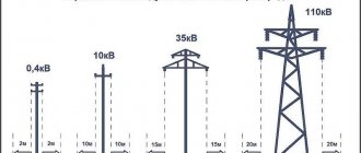
| Dimensions of overhead lines. | ||
| Suspension height line is the distance from the ground to the place where the wire is attached to the support insulator (see figure below). The shortest distance from the ground to the wire is in the middle of the span. Sag boom is the vertical distance from the lowest point of the wire in the span to the straight line between the wire attachment points on the supports. The sag of the wire depends on the air temperature, span length, external load on the wire (wind, ice), material and cross-section of the wire. The maximum sag for overhead lines with voltages up to 1000V with normal spans of 35 - 45 meters is up to 1.2 meters. The clearance of the wire above the ground is the distance from the wires to the surface of the earth at the greatest sag. The dimension of an overhead line at intersections is the smallest vertical distance from the line wires to the surface of highways, railways, rivers, and communication line wires when crossed by an overhead line. The dimension of an overhead line when approaching is the smallest permissible distance from overhead line wires to various objects when the line runs parallel to these objects (for example, buildings, structures, etc.). The dimensions of the wire above the ground , as well as the dimensions of overhead lines at intersections and approaches, are established by the Rules for the Construction of Electrical Installations (PUE) depending on the group of overhead lines and the terrain through which the line route passes. In populated areas, the PUE has the following dimensions of the wire above the ground:
When crossing an overhead line with railways, the size of the wire from the rail head, according to the PUE, must be 7.5 meters; when an overhead line with voltage up to 1000 V crosses tram and trolleybus lines - 8 and 9 meters, respectively, at a distance from the overhead line wires to the supporting cable or contact wire at least 1.5 meters. When an overhead line with a voltage of 6 - 10 kV crosses a tram and trolleybus lines - 9.5 and 11 meters, respectively, with a distance to the supporting cable or contact wire of 3 meters. The distance from overhead line wires with voltage up to 1000V at their greatest deviation from buildings and structures is allowed at least 1.5 meters to balconies and windows and 1 meter to blank walls. For an overhead line with a voltage of 6 - 10 kV - at least 2 meters. The passage of the overhead line over buildings is not allowed. In order to save money, it is possible to jointly hang overhead line wires with a voltage of no more than 380/220 V, radio network (RS) wires and street lighting wires on common supports , as well as jointly hang overhead line wires with a voltage of up to 10 kV and radio network wires. In this case, the wires of the overhead line with a voltage of 380/220 V are located above the RS wires and the vertical distance from the bottom wire of the overhead line to the top wire of the RS, regardless of their placement on the support, must be at least 1.5 meters, and between the wires of the branches from the overhead line and with PC wires at building inputs horizontally of at least 1.5 meters. PC wires are usually located on one side of the support. When jointly suspending overhead line wires with a voltage of 1 - 10 kV and radio network wires with a voltage between wires of more than 360V on common supports, the overhead line wires are also located above the PC wires. In this case, the vertical distance from the bottom wire of the overhead line to the top wire of the RS must be at least 1.2 meters and radio broadcast networks must meet special requirements. |
Overhead power line
Overhead power line (OTL) is a device designed for transmitting or distributing electrical energy through wires with a protective insulating sheath (OIL) or bare wires (OHL) located in the open air and attached using traverses (brackets), insulators and linear fittings to supports or other engineering structures (bridges, overpasses). The main elements of overhead lines are:
- wires;
- safety cables;
- support supporting wires and hummocks at a certain height above ground or water level;
- insulators that isolate wires from the support body;
- linear fittings.
The linear portals of the distribution devices are taken as the beginning and end of the overhead line. According to their design, overhead lines are divided into single-circuit and multi-circuit, usually 2-circuit.
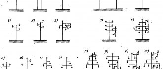
Typically, an overhead line consists of three phases, so the supports of single-circuit overhead lines with voltages above 1 kV are designed to hang three phase wires (one circuit) (Fig. 1); six wires (two parallel circuits) are suspended on the supports of double-circuit overhead lines. If necessary, one or two lightning protection cables are suspended above the phase wires. From 5 to 12 wires are hung on the overhead line supports of a distribution network with voltages up to 1 kV to supply power to various consumers on one overhead line (external and internal lighting, power supply, household loads). An overhead line with a voltage of up to 1 kV with a solidly grounded neutral is equipped with a neutral wire in addition to the phase ones.
Rice. 1. Fragments of a 220 kV overhead line: a – single-circuit; b – double-chain
Wires of overhead power lines are mainly made of aluminum and its alloys, in some cases of copper and its alloys, and are made of cold-drawn wire with sufficient mechanical strength. However, the most widely used are stranded wires made of two metals with good mechanical characteristics and relatively low cost. Wires of this type include steel-aluminum wires with a ratio of the cross-sectional areas of the aluminum and steel parts from 4.0 to 8.0. Examples of the location of phase wires and lightning protection cables are shown in Fig. 2, and the design parameters of overhead lines of a standard voltage range are given in table. 1.
Rice. 2. Examples of the location of phase wires and lightning protection cables on supports : a – triangular; b – horizontal; c – hexagonal “barrel”; d – reverse “Christmas tree”
Table 1. Design parameters of overhead lines
Cable power line
A cable power line (CL) consists of one or more cables and cable fittings for connecting cables and for connecting cables to electrical devices or distribution device buses.
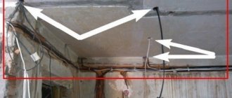
Unlike overhead lines, cables are laid not only outdoors, but also indoors (Fig. 8), in ground and water. Therefore, CLs are susceptible to moisture, chemical aggressiveness of water and soil, mechanical damage during excavation work and soil displacement during heavy rains and floods. The design of the cable and cable laying structures must provide protection from the specified influences.
Rice. 8. Laying power cables indoors and outdoors
According to the rated voltage, cables are divided into three groups: low voltage cables (up to 1 kV), medium voltage cables (6...35 kV), high voltage cables (110 kV and above). According to the type of current, AC and DC cables are distinguished.
Power cables are made as single-core, two-core, three-core, four-core and five-core. High voltage cables are made of single cores; two-core – DC cables; three-core – medium voltage cables.
Low voltage cables are made with up to five cores. Such cables can have one, two or three phase conductors, as well as a neutral working conductor N and a neutral protective conductor PE or a combined neutral working and protective conductor PEN .
Based on the material of the current-carrying conductors, cables with aluminum and copper conductors are distinguished. Due to the scarcity of copper, cables with aluminum conductors are most widely used. Cable paper impregnated with oil rosin, plastic and rubber are used as insulating materials. There are cables with normal impregnation, depleted impregnation and impregnation with a non-drip composition. Cables with depleted or non-draining impregnation are laid along a route with a large difference in heights or along vertical sections of the route.
High voltage cables are made oil-filled or gas-filled. In these cables, the paper insulation is filled with oil or gas under pressure.
Protection of the insulation from drying out and the ingress of air and moisture is ensured by applying a sealed shell to the insulation. The cable is protected from possible mechanical damage by armor. To protect against the aggressiveness of the external environment, an external protective cover is used.
When studying cable lines, it is advisable to note superconducting cables for power transmission lines, the design of which is based on the phenomenon of superconductivity. In a simplified form, the phenomenon of superconductivity in metals can be represented as follows. Coulomb repulsive forces act between electrons as between similarly charged particles. However, at ultra-low temperatures for superconducting materials (which includes 27 pure metals and a large number of special alloys and compounds), the nature of the interaction of electrons with each other and with the atomic lattice changes significantly. As a result, it becomes possible to attract electrons and form so-called electron (Cooper) pairs. The appearance of these pairs, their increase, and the formation of a “condensate” of electron pairs explains the appearance of superconductivity. With increasing temperature, some electrons become thermally excited and go into a single state. At a certain so-called critical temperature, all electrons become normal and the state of superconductivity disappears. The same thing happens when the magnetic field strength increases. The critical temperatures of superconducting alloys and compounds used in technology are 10 - 18 K, i.e. from –263 to –255°С.
The first projects, experimental models and prototypes of such cables in flexible corrugated cryostatic sheaths were implemented only in the 70-80s of the 20th century. As a superconductor, tapes based on an intermetallic compound of niobium with tin, cooled with liquid helium, were used.
In 1986, the phenomenon of high-temperature superconductivity was discovered, and already at the beginning of 1987, conductors of this kind were obtained, which are ceramic materials, the critical temperature of which was increased to 90 K. The approximate composition of the first high-temperature superconductor is YBa2Cu3O7–d (d 2, from them with a cross section of up to 16 mm 2 - single-wire, above - multi-wire.
Wire - one uninsulated or one or more insulated conductors, on top of which, depending on the installation and operating conditions, there may be a non-metallic sheath, winding and (or) braiding with fibrous materials or wire.
Cord - two or more insulated or especially flexible conductors with a cross-section of up to 1.5 mm 2, twisted or laid in parallel, on top of which, depending on the installation and operating conditions, a non-metallic sheath and protective coatings can be applied.
Basic information [ edit | edit code ]
Power line supports are designed for the construction of power lines at a design outside temperature of up to −65 °C and are one of the main structural elements of power lines, responsible for fastening and hanging electrical wires at a certain level.
Depending on the method of hanging wires, supports are divided into two main groups:
- intermediate supports on which the wires are secured in supporting clamps;
- anchor-type supports used for tensioning wires; on these supports the wires are secured in tension clamps.
These types of supports are divided into types that have a special purpose:
- Intermediate straight supports are installed on straight sections of the line. On intermediate supports with suspended insulators, the wires are fixed in supporting garlands hanging vertically; on supports with pin insulators, the wires are secured by wire knitting. In both cases, intermediate supports perceive horizontal loads from wind pressure on the wires and on the support, and vertical loads from the weight of the wires, insulators and the own weight of the support.
- Intermediate corner supports are installed at the angles of rotation of the line with wires suspended in supporting garlands. In addition to the loads acting on intermediate straight supports, intermediate and anchor-corner supports also perceive loads from the transverse components of the tension of wires and cables. At transmission line rotation angles of more than 20°, the weight of the intermediate corner supports increases significantly. At large rotation angles, anchored corner supports are installed.
When installing anchor supports on straight sections of the route and suspending wires on both sides of the support with equal tensions, the horizontal longitudinal loads from the wires are balanced and the anchor support works in the same way as an intermediate one, that is, it perceives only horizontal transverse and vertical loads. If necessary, the wires on one and the other side of the support can be pulled with different wire tensions. In this case, in addition to horizontal transverse and vertical loads, the support will be affected by horizontal longitudinal load.
When installing anchor supports at corners, the anchor-corner supports also take the load from the transverse components of the tension of the wires and cables.
End supports are installed at the ends of the line. Wires extend from these supports and are suspended on substation portals.
In addition to the listed types of supports, special supports are also used on lines: transpositional, used to change the order of the wires on the supports; branch lines - for making branches from the main line; supports for large crossings across rivers and bodies of water, etc.
Wooden, steel and reinforced concrete supports are used on power lines. Experimental structures made of aluminum alloys and composite materials have also been developed.
Steel is the main material from which metal supports and various parts (traverses, cable supports, guy wires) of the supports are made. The advantage of steel supports compared to reinforced concrete ones is their high strength with low weight. Possibility of reuse throughout the entire period of operation.
According to the design of the shaft, steel supports can be classified into three main schemes - tower (single- or multi-post), portal or cable-stayed; according to the method of fastening to the foundations - free-standing supports and guyed supports; according to the method of connecting elements they are divided into welded and bolted . Also, steel supports are divided into supports of a flexible structure and supports of a rigid structure.
Metal supports are made both from rolled steel angles (an isosceles angle is used) and from bent steel profiles of constant and variable sections (this combines the advantages of the designs of steel polyhedral transmission line supports and steel lattice tower-type supports), in addition, high transition supports can be manufactured from steel pipes.
In the CIS there are several main centers for the production of steel structures for power transmission line supports - central, Ural and Siberian.