One of the most important points when installing a SIP wire is to give it the correct tension.
When constructing VLI and VLZ, you can use modern and super-expensive tools and devices (motor winch), use reliable European fittings (Ensto and Sicame), but if you make a mistake in just one moment, roughly speaking, tighten the SIP more than required, and in a year all your the work will go down the drain.
The winter period of operation with our frosts does not forgive such mistakes.
Of course, any electrician understands that neither SIP, nor bare wires A or AC, and even modern innovative AEROZ cannot be pulled into a string.
Although this is visually beautiful from the outside, it significantly reduces the reliability of the operating overhead line. Even supports that can easily withstand large bending moments will begin to bend and tilt.
Or one of the anchor elements will not withstand the load and will break off. When installing the hook correctly on the support, the lock on the bandage tape must first come loose.
The SIP itself will fall to the ground without serious damage to the shell. But the installation of reinforcement is not always carried out using steel banding tape.
Through hooks are often used.
How to correctly calculate the tension of an insulated line with SIP wires, so that at low temperatures large bending moments do not appear, and the wire itself and the fittings are not subjected to increased loads?
Installation tables for SIP
Assembly tables will help you in this matter. They are present in almost any typical project.
You can view and download tables of tension and calculated sag (from Ensto) for SIP-4 wire from here (from page 32 to page 104).
However, do not forget to recalculate the mounting tension throughout the entire wire. Since the plates contain data on mechanical stress.
Also, to convert mPa into a more convenient format kgf or kN, used on dynamometer scales, you can use a convenient online converter using the link here.
Let's look at two extreme cases as an example:
- During installation, a minimum cross-section of 4*25 is used
- and vice versa maximum 4*120
From the tabular data you can clearly see how the SIP sag of a correctly tensioned wire changes depending on the temperature.
With a span length of 30 meters between the supports and a temperature of +20C, the sag should be about half a meter. The tension for the same wire does not exceed 84 kg.
This is not a very large value, and many are tempted to pull the line tighter. Fortunately, this can be done even manually by two or three fitters, without the use of special winches.
However, in winter, when the ambient temperature stays below 20 degrees for a long time and reaches -30C, everything changes dramatically. A correctly tensioned SIP with a cross section of 25mm2 already sags by only 14cm! And if you tighten it a little in the summer, then this is where the extra bending and tearing forces arise.
This is all transferred to the supports and anchor clamps. At -30C, the gravity increases 4 times and reaches 323 kg.
For SIP 4*120 at t=+20C, the sag will be 86cm. And at -30C it will rise to 0.6m. On the one hand, visually the difference here will not be so noticeable.
However, look at the gravitational force for yourself. Even in summer it exceeds 200 kg, not to mention the winter maximum or ice.
All these tables are designed in such a way that under any circumstances, even the worst (temperature minus 40C or minus 5C, but with ice), the gravitational forces are achieved to the maximum possible, but at the same time do not go beyond the norm.
That is, if in the summer under good weather conditions you pull the wires according to the table, and not “by eye,” then in the winter, even in the worst case scenario, nothing will break or break.
Installation tables and sag for high-voltage SIP-3 can be downloaded from here (Design Guide - Book 4.1 page 26-50).
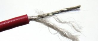
The SIP wire itself is very durable. It differs significantly in its properties from the uninsulated bare speaker wire.
Therefore, you cannot pull it into a string.
If you do not have special measuring dynamometers, then it is better to let it sag. The main thing is to ensure clearance above the road.
At least there will be no overloads or emergency shutdowns due to this. And VLI-0.4 kV will quietly serve its allotted 40 years.
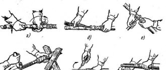
How to use these tables in practice in real conditions? In order to correctly stretch the SIP line along them, you can use two methods:
- use a dynamometer
- manually measure the sag in one span
2.4.29
The distances between bare wires on the support and in the span, according to the conditions of their approach in the span with the greatest sag up to 1.2 m, must be no less than:
with a vertical arrangement of wires and an arrangement of wires with a horizontal displacement of no more than 20 cm: 40 cm in regions I, II and III on ice, 60 cm in regions IV and special regions on ice;
with other wire locations in all areas on ice at wind speeds during ice: up to 18 m/s - 40 cm, more than 18 m/s - 60 cm.
If the maximum sag is more than 1.2 m, the indicated distances must be increased in proportion to the ratio of the largest sag to the sag equal to 1.2 m.
SIP tension through a dynamometer
When using a dynamometer, the tension force taken from the table alone is not enough. It is also necessary to know the given anchor span. What it is?
This is a span or spans on an overhead line between two anchor supports. Between them there can be either one or several intermediate supports.
At the same time, the calculation tables indicate data specifically for the given spans. They represent a certain average mathematical value.
This is due to the fact that the lines are not always uniform. And the distances between the supports sometimes differ by several tens of meters.
Let's say you have two anchors and one intermediate support between them. The length of the first span is 40 meters, and the second is only 10 m. It is clear that with the same tension, in a larger span the sag of the boom will always be greater.
Therefore, the gravity itself is determined precisely for the average value. The average reduced span is calculated using the following formula:
- Li is the length of one span in meters or km
- ∑Li – sum of all spans
By calculating the value using this formula, you will get the final reduced span. For our case (40m+10m) it will be 25m.
Next, using interpolation in the table, we look for the required tension. In the tabular data for spans up to 40m, the values are divided in 2m increments.
For longer distances, integer values of 40-45-50m are usually used. You will need to find the closest one.
Having found out the required value, tension the SIP on the final support through a dynamometer.
In order to do this correctly, simply monitor the readings of the scale of the measuring device so as not to go beyond the limits of this effort.
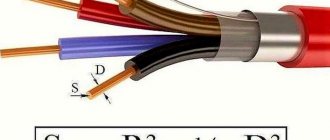
Determination of the cross-section of wires or cables based on the permissible voltage loss
What fire extinguishers are used when extinguishing electrical installations
The selection of the cross-section of conductors in the cable network must be made according to the permissible voltage loss, which is set in such a way that voltage deviations for all electrical equipment connected to this network do not go beyond the permissible limits.
Rated voltages at the output of power supply systems (according to GOST 21128-83):
According to GOST 13109-97:
- The normally permissible value of steady-state voltage deviation is ±5.
- The maximum permissible value of steady-state voltage deviation is ±10.
Line active and inductive reactance
The active resistance of the line (Ohm/km) is equal to:
Value of inductive reactance of conductors Calculation of a network based on voltage loss without taking into account the inductive reactance of wires is permissible in the following cases:
- for DC network;
- AC at cosφ = 1
- for networks made with cables or insulated wires laid in pipes on rollers or insulators, if their cross-section does not exceed the values indicated in the table below.
Formulas for calculating the cross-section of conductors for a given voltage loss
Three-phase AC line:
Two-wire AC or DC line:
Where γ is the conductivity of the wire material, m/(Ohm×mm2);
Un — rated network voltage, kV (for a three-phase network Un — phase-to-phase voltage);
∆Uadd – permissible voltage loss in the line, the cross-section of which is determined, %.
F—conductor cross-section, mm2;
∑P∙L=P1∙L1+P2∙L2+…—the sum of the products of the loads flowing along the sections of the line and the length of these sections; loads should be expressed in kilowatts, lengths in meters;
∑Iа∙L= Iа1 ∙L1+ Iа2 ∙L2+…—the sum of the products of the active components of currents passing through the sections and the lengths of the sections;
Currents must be expressed in amperes, lengths in meters.
The active components of the current (A) are determined by multiplying the current values by the power factor values Ia = I∙ cos ɸ.
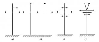
Distance between transmission line towers: 10 kV, 110 kV and 35 kV transmission line poles
The electricity everyone needs is transmitted through wires suspended from poles of various designs and power lines. For safety, the distance between power line supports and their height are of great importance. GOST regulates all sizes based on the current strength in the wires, material and design of the support. The location of power transmission line supports in open areas or in populated areas is also of great importance.
Factors on which the distance between pillars depends
In different places, the distance between power line poles and the height of the wire differ. The values are calculated based on the fact that the tension of the wire and its sagging will create prevailing horizontal loads between the supports.
The second important element is the strength of the icing in a particular area and the resistance to wind swing. The value is calculated for each region separately depending on climatic conditions. In addition, what distance should be between the pillars and supports depends on the following factors:
- network voltage,
- the type of settlement through which the line passes,
- distance from populated areas,
- number of overhead lines,
- wire type.
Adjustment of distances between power transmission line poles is carried out primarily in populated areas. Based on general requirements, supports should not block free access to the yard, block the path for pedestrians, or stand directly in front of the front facades of buildings and entrances to houses.
A fence is installed on the side of the road to prevent cars from hitting the supports. These are concrete pillars, bollards and high barrier curbs.
Each high-voltage pole must be marked. At a height of 2.5–3 m, the following data is applied:
- Serial number.
- Network voltage value.
- Year of installation of the structure.
- Width of the security zone.
- Distance from ground to communication cables.
- Phone number of the owner - the organization operating this network.
Metal structures are protected from corrosion and are regularly coated with a protective primer or ship paint.
The numbering of supports is carried out from the current source.
The maximum deflection of wires is calculated taking into account icing, which is divided into 6 categories, and wind force. Tensioners are installed at the suspension points, ensuring a minimum angle of deviation of the horizontal position of the cable and the least sagging.
Bare wire is used for lines outside cities and towns. It will be installed at the maximum possible height directly on the insulators using special bolted tires.
Mains voltage
The distance between the supports is determined depending on the voltage in the wires they carry:
- 0.4–1 kV – distance within 30–75 m,
- 10 kV – spans up to 200 m,
- 220 kV – distance between supports up to 400 m,
- over 330 kV - supports can be located from each other at a maximum distance of 700 m.
The wires are suspended in parallel on insulators at a height that also depends on the voltage. If it is up to 1000 V, then the line is fixed at a height of 7 m.
The permissible sag and the distance to the bottom point are also determined depending on the voltage. In cities, towns of individual housing construction and SNT, the lowest sagging point should be higher than 6 m from the ground.
Instructions for those on how to tighten a sagging conductor on a line
First of all, you shouldn’t panic or be nervous, but you also shouldn’t get close to the pillars.
Wait for the specialists to arrive and under no circumstances try to tighten the sagging cable and fix the problem yourself - this can result in very sad consequences.
Do not prop it up, and certainly do not try to cut off a piece of the cable to take it for yourself.
Damaged sections of lines pose a danger, even if there is no electricity in them (if you do not know what step voltage is, then read up, this information may later turn out to be vital).
What to do if the wire sags?
If the wire is sagging, then you should never be near it. Also, you should not try to bite off the wire yourself for profit. This can cause significant electric shock, which in some cases can be fatal.
Typically, a power line is divided into certain sections for which an individual owner will be responsible. It is he who will have to notify the relevant authorities who will carry out the inspection. Performing an alert today is problematic, since you need to report the sagging wire to the appropriate authorities.
2.5.270
The distance from the lowest point of sag of overhead line wires in normal and emergency modes to the level of high (flood) waters in navigable sections of rivers, canals, lakes and reservoirs is determined as the sum of the maximum size of vessels and the shortest distance from the overhead line wires to the size of vessels according to Table 2.5.37 .
Table 2.5.37 Minimum distance when crossing overhead lines with water spaces
| Distance | Shortest distance, m, at overhead line voltage, kV | |||||
| Up to 110 | 150 | 220 | 330 | 500 | 750 | |
| For navigable sections of rivers, canals, lakes and reservoirs from vertical wires: | ||||||
| up to the maximum size of vessels or rafting in normal overhead line mode | 2 | 2,5 | 3,0 | 3,5 | 4,0 | 5,5 |
| the same, but if the wire breaks in the adjacent span | 0,5 | 1,0 | 1,0 | 1,5 | — | — |
| to the upper working platforms for ship maintenance (wheelhouse roof, etc.) in backwaters, ports and other settling points | — | — | — | 11,0 | 15,5 | 23,0 |
| to ice level | 6,0 | 6,5 | 7,0 | 7,5 | 8,0 | 12,0 |
| For non-navigable sections of rivers, canals, lakes and reservoirs from vertical wires: | ||||||
| to high water level* | 5,5 | 6,0 | 6,5 | 7,0 | 7,5 | 10,0 |
| to ice level | 6,0 | 6,5 | 7,0 | 7,5 | 8,0 | 12,0 |
________________
* The shortest distance allows passage of floating craft up to 3.5 m high.
The sag of the wire is determined at the highest air temperature without taking into account the heating of the wires by electric current.
The level of high (flood) waters is accepted with a probability of exceedance (probability) of 0.01 (recurrence rate 1 time in 100 years) for overhead lines 500-750 kV and 0.02 (recurrence rate 1 time in 50 years) for overhead lines 330 kV and below.
The distances from the lowest point of sag of the overhead line wire to the ice level must be no less than those indicated in Table 2.5.37. In this case, the sag of the wire is determined at the calculated linear ice load according to 2.5.55 and the air temperature during ice conditions according to 2.5.51.
When crossing overhead lines of 330 kV and above long-term mooring sites for vessels (backwaters, ports and other settling points), the shortest distance to the upper working platforms for vessel maintenance must be ensured according to Table 2.5.37. The sag of the wire is determined at air temperature according to 2.5.17 without taking into account the heating of the wire by electric current at the maximum permissible values of the intensity of the electric and magnetic components of the electromagnetic field.
How to tighten a sagging section of line
If you are the owner of the site or a responsible person and have an act where the demarcation points are clearly marked, as well as the supply of electricity to the site, then the responsibility for tensioning the cable falls on your shoulders.
Attention! Any actions with power lines must be done by completely turning off the electricity, de-energizing the area and turning off the distribution point. At the same time, in order to protect yourself to the maximum, in order to tension the cable, you need to apply grounding on both sides of the area.
If you are a specialist in this field, but not the owner of this land, then you can act only with the permission of the owner or other competent authority (for this you need to submit an appropriate application and obtain official permission).
And only then should you disconnect the line from the voltage and start working.