Insulation resistance values for electrical equipment and systems
(PEARL/NETA MTS-1997 Standard Table 10.1)
| Rated maximum equipment voltage | Megger class | Minimum insulation resistance value |
| 250 V | 500 V | 25 MOhm |
| 600 V | 1000 V | 100 MOhm |
| 5 kV | 2500 V | 1000 MOhm |
| 8 kV | 2500 V | 2000 MOhm |
| 15 kV | 2500 V | 5000 MOhm |
| 25 kV | 5000 V | 20000 MOhm |
| 35 kV | 15000 V | 100000 MOhm |
| 46 kV | 15000 V | 100000 MOhm |
| 69 kV | 15000 V | 100000 MOhm |
1 MΩ Rule for Equipment Insulation Resistance Value
Depending on the rated voltage of the equipment:
> 1 kV = 1 MΩ per 1 kV
According to IE Rules - 1956
When 1000 V is present between each live conductor and earth for one minute, the insulation resistance of high voltage installations shall be not less than 1 MΩ or as specified by the Bureau of Indian Standards. Medium Voltage and Low Voltage Installations - If 500 V is present between each live conductor and ground for one minute, the insulation resistance of Medium Voltage and Low Voltage Installations shall be not less than 1 MΩ or as specified by the Bureau of Indian Standards. According to CBIP specifications, acceptable values are 2 MΩ per kV.
Medium Voltage and Low Voltage Installations - If 500 V is present between each live conductor and ground for one minute, the insulation resistance of Medium Voltage and Low Voltage Installations shall be not less than 1 MΩ or as specified by the Bureau of Indian Standards.
According to CBIP specifications, acceptable values are 2 MΩ per kV
Water-cooled winding
Measuring the insulation resistance of an electric motor that has a direct water-cooled winding should be carried out using a megohmmeter with built-in shielding. Here you need to pay attention to the fact that the clamp that is connected to the screen must be connected to the drainage collector. The collectors themselves should not have any metal connection with the external distillate winding power supply system.
After all measurements in the circuit are completed, it is necessary to discharge it. For this purpose, an electrical connection is made to the grounded body of the machine. If the rated operating voltage of the windings is 3 kV or more, then the electrical connection time to the housing should be as follows:
- electrical equipment with a power of up to 1000 kW (kV*A) - duration of at least 15 seconds for a complete reset;
- if you need to discharge a machine whose power exceeds 1000 kW, then the time should be increased to 1 minute or more.
The same megohmmeter can also be used for discharge. If you use a device with a power rating of 2.5 kV, then the time to discharge any electric motor, regardless of its power, is at least 3 minutes.
2. Insulation resistance value for transformer
Insulation resistance testing is necessary to determine the insulation resistance of individual windings to ground or between individual windings. In this type of testing, insulation resistance is usually either measured directly in MΩ or calculated from the applied voltage and the magnitude of the leakage current.
When measuring insulation resistance, it is recommended to always ground the frame (and core). Short-circuit each transformer winding to the bushing terminals. After this, measure the resistance between each winding and all other grounded windings.
Insulation resistance testing: between high voltage side and ground, and between high voltage side and low voltage side. HV1 (2, 3) - Low voltage 1 (2, 3); LV1 (2, 3) - High voltage 1 (2, 3))
When measuring insulation resistance, never leave the transformer windings ungrounded. To measure the resistance of a grounded winding, it is necessary to remove solid grounding from it. If it is not possible to remove the ground, as is the case with some windings with solidly grounded neutrals, the insulation resistance of such a winding will not be measurable. Consider them part of the grounded section of the circuit.
Testing must be done between windings and between winding and ground (E). On three-phase transformers, it is necessary to test the winding (L1, L2, L3) minus the ground for transformers with a delta connection or the winding (L1, L2, L3) with ground (E) and neutral (N) for transformers with a star connection.
Insulation resistance value for transformer
| Transformer | Formula |
| Single phase transformer | Insulation resistance value (MΩ) = CXE / (√kVA) |
| Three-phase transformer (star) | Insulation resistance value (MΩ) = CXE (P – n) / (√kVA) |
| Three-phase transformer (delta) | Insulation resistance value (MΩ) = CXE (P – P) / (√kVA) |
Where C = 1.5 for oil-filled transformers with an oil tank, 30 for oil-filled transformers without an oil tank or for dry transformers.
Temperature correction factor (relative to 20°C)
| Temperature correction factor | |
| °C | Correction factor |
| 0 | 0,25 |
| 5 | 0,36 |
| 10 | 0,50 |
| 15 | 0,720 |
| 20 | 1,00 |
| 30 | 1,98 |
| 40 | 3,95 |
| 50 | 7,85 |
Example for a three-phase transformer 1600 kVA, 20 kV / 400 V:
- insulation resistance value on high voltage side = (1.5 x 20000) / √1600 = 16000 / 40 = 750 MOhm at 20°C;
- insulation resistance value on low voltage side = (1.5 x 400) / √1600 = 320 / 40 = 15 MOhm at 20°C;
- insulation resistance value at 30°C = 15 x 1.98 = 29.7 MOhm.
Transformer winding insulation resistance
| Transformer winding voltage | Megger class | Minimum insulation resistance value for liquid transformer | Minimum insulation resistance value for a dry transformer |
| 0 – 600 V | 1 kV | 100 MOhm | 500 MOhm |
| 600 V – 5 kV | 2.5 kV | 1000 MOhm | 5000 MOhm |
| 5 kV – 15 kV | 5 kV | 1000 MOhm | 5000 MOhm |
| 15 kV – 69 kV | 5 kV | 10000 MOhm | 50000 MOhm |
Transformer insulation resistance value
| Voltage | Test voltage (DC), low voltage side | Test voltage (DC), high voltage side | Minimum insulation resistance value |
| 415 V | 500 V | 2.5 kV | 100 MOhm |
| Up to 6.6 kV | 500 V | 2.5 kV | 200 MOhm |
| 6.6 kV – 11 kV | 500 V | 2.5 kV | 400 MOhm |
| 11 kV – 33 kV | 1000 V | 5 kV | 500 MOhm |
| 33 kV – 66 kV | 1000 V | 5 kV | 600 MOhm |
| 66 kV – 132 kV | 1000 V | 5 kV | 600 MOhm |
| 132 kV – 220 kV | 1000 V | 5 kV | 650 MOhm |
Measuring the insulation resistance of a transformer:
- turn off the transformer and disconnect jumpers and lightning rods;
- discharge the interturn capacitance;
- completely clean all bushings;
- short-circuit the windings;
- Protect the terminals to prevent surface leakage across the terminal insulators;
- record the ambient temperature;
- connect test leads (avoid additional connections);
- Apply test voltage and record readings. The insulation resistance value 60 seconds after applying the test voltage is taken as the insulation resistance of the transformer at the testing temperature;
- The neutral terminal of the transformer must be disconnected from ground during testing;
- Also, during testing, all connections to the ground of the lightning rod on the low voltage side must be disconnected;
- due to the inductive characteristics of the transformer, insulation resistance readings must be taken only after the test current has stabilized;
- Do not take resistance readings while the transformer is under vacuum.
Transformer connections when testing insulation resistance (at least 200 MOhm)
Transformer with two windings 1. (High voltage winding + low voltage winding) - ground 2. High voltage winding - (low voltage winding + ground) 3. Low voltage winding - (high voltage winding + ground)
Three Winding Transformer 1. High Voltage Winding - (Low Voltage Winding + Tap Winding + Ground) 2. Low Voltage Winding - (High Voltage Winding + Tap Winding + Ground) 3. (High Voltage Winding + Low Voltage Winding + Tap Winding) - Ground 4. Tap Winding – (high voltage winding + low voltage winding + ground)
Autotransformer (two windings) 1. (High voltage winding + low voltage winding) - ground
Autotransformer (three windings) 1. (High voltage winding + low voltage winding) – (tap winding + ground) 2. (High voltage winding + low voltage winding + tap winding) – ground 3. Tap winding – (high voltage winding + low voltage winding + ground)
For any insulation, the measured insulation resistance should not be less than:
- high-voltage winding – ground 200 MOhm;
- low-voltage winding – ground 100 MOhm;
- high-voltage winding – low-voltage winding 200 MOhm.
Factors affecting the transformer insulation resistance value
The insulation resistance value of transformers is affected by the following:
- condition of the surface of the terminal bushing;
- oil quality;
- winding insulation quality;
- oil temperature;
- duration of use and test voltage value.
Why is insulation testing necessary?
It is important to understand here that those materials that are used as an insulating winding for an electric motor are not inherently pure dielectrics. All of them conduct electricity to a greater or lesser extent. This largely depends on their physical and chemical properties.
You might be interested in: Psychology. Discretion is...
In addition to the fact that these factors influence the insulation resistance indicator, it is also necessary to take into account the fact that such a characteristic as humidity plays a very important role. In addition, mechanical damage, as well as possible various contaminations and dust can negatively affect this characteristic. Because of all these factors, the operation of measuring resistance is an integral part of the operating process of an electric motor.
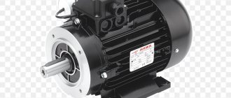
Insulation resistance value for electric motor
An insulation tester is used to measure the grounded motor winding resistance (E).
- for rated voltages below 1 kV, measurement is carried out with a 500 V DC megger;
- for rated voltages above 1 kV, measurement is carried out with a 1000 V DC megger;
- According to IEEE 43 Article 9.3, the following formula should be applied: minimum insulation resistance value (for rotating machine) = (Rated Voltage (V) / 1000) +1.
Insulation resistance value for electric motor
In accordance with IEEE 43 1974, 2000
| Insulation resistance value in MOhm | |
| Insulation resistance (minimum) = kV + 1 | For most windings made before approximately 1070, all field windings and other windings not described below. |
| Insulation resistance (minimum) = 100 MΩ | For most DC rotors and AC windings manufactured after approximately 1070 (pattern coils). |
| Insulation resistance (minimum) = 5 MΩ | For most machines with non-patterned stator coils and patterned coils rated below 1 kV. |
Example 1: For a three-phase electric motor 11 kV
- insulation resistance value = 11 + 1 = 12 MΩ, but according to IEEE43 should be 100 MΩ.
Example 2: For a 415V three-phase motor
- insulation resistance value = 0.415 + 1 = 1.41 MΩ, but according to IEEE43 should be 5 MΩ;
- as per IS 732 minimum insulation resistance value for electric motor = (20 x Voltage (p-p)) / (1000 + 2 x kW).
Motor insulation resistance value according to NETA ATS 2007 Section 7.15.1
| Motor nameplate (B) | Test voltage | Minimum insulation resistance value |
| 250 V | 500 V DC | 25 MOhm |
| 600 V | 1000 V DC | 100 MOhm |
| 1000 V | 1000 V DC | 100 MOhm |
| 2500 V | 1000 V DC | 500 MOhm |
| 5000 V | 2500 V DC | 1000 MOhm |
| 8000 V | 2500 V DC | 2000 MOhm |
| 15000 V | 2500 V DC | 5000 MOhm |
| 25000 V | 5000 V DC | 20000 MOhm |
| 34500 V | 15000 V DC | 100000 MOhm |
Submersible motor insulation resistance value
| Submersible motor insulation resistance value | |
| Electric motor outside the well (without cable) | Insulation resistance value |
| New electric motor | 20 MOhm |
| Used motor that can be reinstalled | 10 MOhm |
| Electric motor installed in a well (with cable) | |
| New electric motor | 2 MOhm |
| Used motor that can be reinstalled | 0.5 MOhm |
Measuring insulation in relation to various parts
When it comes to measuring the insulation resistance of an electric motor, you need to understand that it is determined in relation to something. If measuring work is carried out in relation to the machine body or windings, then they must be carried out alternately for each circuit.
Measuring the insulation resistance of an electric motor, or rather its windings with three-phase current, which are usually connected in connections such as star or delta, is carried out immediately for the entire winding in relation to the housing, and not one by one, as was described before.
Insulation Resistance Value for Electrical Cables and Wiring
Insulation testing requires disconnecting cables from the panel or equipment and from the power source. Wiring and cables should be tested relative to each other (phase to phase) with the ground cable (E). The IPCEA (Insulated Power Cable Engineers Association) offers a formula for determining the minimum insulation resistance values.
R = K x Log 10 (D/d)
R = Insulation resistance value in megohms for 305 meters of cable K = Insulating material constant. (Electrical insulating lacquer cloth = 2460, thermoplastic polyethylene = 50000, composite polyethylene = 30000) D = Outside diameter of conductor insulation for solid wire or cable (D = d + 2c + 2b diameter of solid cable) d = Diameter of conductor c = Thickness of conductor insulation b = Insulating sheath thickness
High voltage testing of new XLPE cable (according to ETSA standard)
| Application | Test voltage | Minimum insulation resistance value |
| New Cables – Jacket | 1 kV DC | 100 MOhm |
| New cables - Insulation | 10 kV DC | 1000 MOhm |
| After recovery – Shell | 1 kV DC | 10 MOhm |
| After recovery - Isolation | 5 kV DC | 1000 MOhm |
11 kV and 33 kV cables between core and earth (according to ETSA standard
| Application | Test voltage | Minimum insulation resistance value |
| New 11 kV cables – Sheath | 5 kV DC | 1000 MOhm |
| 11 kV after restoration – Shell | 5 kV DC | 100 MOhm |
| 33 kV without connected TF | 5 kV DC | 1000 MOhm |
| 33 kV with connected TF | 5 kV DC | 15 MOhm |
11 kV and 33 kV cables between cores and ground
Measuring the insulation resistance value (between conductors (cross insulation))
- The first conductor to be measured for cross-insulation must be connected to the Line terminal of the megger. The other conductors are connected together (using alligator clips) and connected to the Earth terminal of the megger. At the other end, the conductors are not connected;
- then turn the knob or press the megger button. The meter display will show the insulation resistance between conductor 1 and the remaining conductors. Insulation resistance readings should be recorded;
- then connect another conductor to the Line terminal of the megger, and connect the other conductors to the ground terminal of the megger. Take a measurement.
Measuring insulation resistance value (insulation between conductor and ground)
- connect the conductor under test to the Line terminal of the megger;
- connect the Earth terminal of the megohmmeter to ground.;
- turn the knob or press the megohmmeter button. The meter display will show the insulation resistance of the conductors. After maintaining the test voltage for a minute until a stable reading is obtained, record the insulation resistance value.
Measured values:
- If, during periodic testing, the insulation resistance of an underground cable at the corresponding temperature is from 5 MΩ to 1 MΩ per kilometer, this cable must be included in the replacement program;
- if the measured insulation resistance of an underground cable at the corresponding temperature is from 1000 kOhm to 100 kOhm per kilometer, this cable should be replaced urgently, within a year;
- If the measured cable insulation resistance is less than 100 kOhm per kilometer, this cable should be replaced immediately as an emergency cable.
Preparing the electric motor for testing
In addition, before proceeding to check the insulation resistance of the electric motor, it is necessary to open its input device, which is called boron. After this, the insulators must be thoroughly wiped to remove any dirt and dust. Only after this is it possible to connect the measuring device according to its diagram.
When directly measuring resistance, it is necessary to take readings from the device every 15 seconds. The real value of the winding resistance is the value that will be taken 60 seconds after the start of the procedure. And the ratio of the values taken in 60 seconds to the value obtained after 15 seconds is called the absorption coefficient, which was mentioned earlier.
Insulation resistance value for transmission line/distribution line
| Equipment | Megger class | Minimum insulation resistance value |
| Substation equipment | 5 kV | 5000 MOhm |
| EHV lines | 5 kV | 10 MOhm |
| HT lines | 1 kV | 5 MOhm |
| LT lines/service lines | 0.5 kV | 5 MOhm |
Measuring the gaps between the steel of the rotor and stator.
The size of the air gaps is determined using a special set of calibrated feelers (plate - for measuring gaps up to 2mm and wedge - for gaps up to 20mm). Measurements are made in the intergland space. The width of the probe should be used less than the width of the teeth, and when taking measurements, the probe should not fall on the grooved wedge or bandage. For AC electric motors, measurements are made at several diametrically opposite points - four or eight, depending on the size of the motor. With a short length of active steel (up to 300 mm), the gaps can be measured on one side, with a longer length - on both sides. The average gap is equal to the ariphretic mean value of the measured gaps. In large electric motors, the air gap in the lower part is allowed to be 0.1÷0.3 mm larger than in the upper part.
The dimensions of the air gaps at diametrically opposite points or points shifted by 90 relative to the rotor axis should differ by no more than 10% of the average size.
Insulation resistance value for substation equipment
Typical resistance values for substation equipment are:
Typical insulation resistance value for substation equipment
| Equipment | Megger class | Minimum insulation resistance value | |
| Circuit breaker | (Phase – Earth) | 5 kV, 10 kV | 1000 MOhm |
| (Phase - Phase) | 5 kV, 10 kV | 1000 MOhm | |
| Control circuit | 0.5 kV | 50 MOhm | |
| CT/PT | (Primary – Earth) | 5 kV, 10 kV | 1000 MOhm |
| (Secondary – Phase) | 5 kV, 10 kV | 50 MOhm | |
| Control circuit | 0.5 kV | 50 MOhm | |
| Insulator | (Phase – Earth) | 5 kV, 10 kV | 1000 MOhm |
| (Phase - Phase) | 5 kV, 10 kV | 1000 MOhm | |
| Control circuit | 0.5 kV | 50 MOhm | |
| L.A. | (Phase – Earth) | 5 kV, 10 kV | 1000 MOhm |
| Electric motor | (Phase – Earth) | 0.5 kV | 50 MOhm |
| Switchgear LT | (Phase – Earth) | 0.5 kV | 100 MOhm |
| Transformer LT | (Phase – Earth) | 0.5 kV | 100 MOhm |
Insulation resistance value of substation equipment in accordance with DEP standard:
| Equipment | Measurement | Insulation resistance value at the time of commissioning (MOhm) | Insulation resistance value at the time of service (MOhm) |
| Switchgear | High voltage bus | 200 MOhm | 100 MOhm |
| Low voltage bus | 20 MOhm | 10 MOhm | |
| Low voltage wiring | 5 MOhm | 0.5 MOhm | |
| Cable (minimum 100 meters) | High voltage and low voltage | (10 x kV)/km | (kV)/km |
| Electric motor and generator | Phase – Earth | 10 (kV + 1) | 2 (kV + 1) |
| Transformer immersed in oil | High voltage and low voltage | 75 MOhm | 30 MOhm |
| Transformer, dry type | High voltage | 100 MOhm | 25 MOhm |
| Low voltage | 10 MOhm | 2 MOhm | |
| Stationary equipment/tools | Phase – Earth | 5 kOhm per volt | 1 kOhm per volt |
| Removable equipment | Phase – Earth | 5 MOhm | 1 MOhm |
| Distribution equipment | Phase – Earth | 5 MOhm | 1 MOhm |
| Circuit breaker | Power circuit | 2 MΩ per kV | — |
| Control circuit | 5 MOhm | — | |
| Relay | DC Circuit - Ground | 40 MOhm | — |
| Circuit LT - Ground | 50 MOhm | — | |
| LT – DC circuit | 40 MOhm | — | |
| LT–LT | 70 MOhm | — |
Drying the electric motor
If the reduced resistance is caused by moisture getting on the motor or storage in a damp room, then the electric machine can be dried. To do this, you need to disassemble it - remove the bearing shield covers and remove the rotor. This is done to allow moisture to escape freely.
Advice! You can remove only one shield, and remove the rotor along with the second one.
After disassembly, drying is carried out in one of the following ways:
- By applying reduced voltage to the windings. The current should not exceed the rated current.
- Insert the heater into the stator. Most often, an incandescent lamp of 60-100W is used for this.
A day later, the insulation is re-measured. If the resistance increases, then the drying continues until it is completely dry; if not, then the engine is sent for medium repair to a specialized enterprise. This type of repair includes impregnation of the windings with varnish and repeated drying.
Insulation testing is a necessary part of motor testing. The types of inspections in some cases are determined by the PUE and other regulatory documents.
Insulation Resistance Value for Household/Industrial Wiring
Low resistance between phase and neutral conductors or between live conductors and earth will result in leakage current. This leads to deterioration of insulation, as well as energy losses, which will result in increased operating costs for the installed system. At normal supply voltages, the phase-to-phase-neutral-to-earth resistance should never be less than 0.5 MΩ.
In addition to the leakage current due to the active resistance of the insulation, there is also a leakage current due to its reactance, since it acts as the dielectric of a capacitor. This current does not dissipate any energy and is not harmful, but we need to measure insulation resistance, so DC voltage is used to prevent reactance measurement from being included in the test.
Single phase wiring
Insulation resistance testing between phase-neutral and ground should be performed on the entire installation with the power switch turned off, with the line and neutral connected together, with lamps and other equipment disconnected but with circuit breakers closed, and with all circuit breakers closed.
If bidirectional switching is used, only one of the two wires will be tested. To test a different wire, you must operate both bi-directional switches and retest the system. If necessary, the installation can be tested as a whole, but then a value of at least 0.5 MΩ must be obtained.
Testing the Insulation Resistance Value for Single-Phase Wiring
Three-phase wiring
In the case of a very large installation with many parallel connections to ground, lower readings can be expected. In this case, it is necessary to repeat the testing after partitioning the system. Each of these parts must meet minimum requirements.
Testing the insulation resistance value for three-phase wiring
Insulation resistance testing should be performed between phase-phase-neutral-ground. The minimum acceptable value for each test is 0.5 MΩ.
Low Voltage Insulation Resistance Testing
| Circuit voltage | Test voltage | Insulation resistance value (minimum) |
| Ultra Low Voltage | 250 VDC | 0.25 MOhm |
| Up to 500 V, except as stated above | 500 V DC | 0.5 MOhm |
| From 500 V to 1 kV | 1000 V DC | 1.0 MΩ |
Minimum insulation resistance value = 50 MΩ / number of electrical outlets (all electrical points with installation elements and plugs)
Minimum insulation resistance value = 100 MΩ / number of electrical outlets (all electrical outlets without installation elements and plugs)
Reasons for low resistance
There are several reasons for low insulation resistance.
Electric machine overheating
This situation occurs due to an overload of the electric machine or a break in one of the phases in three-phase electric motors. It is impossible to eliminate this problem in a workshop and the device must be sent to a specialized enterprise to replace the windings.
Protection devices help prevent such a malfunction:
- The thermal relay turns off the electric machine when overloaded;
- The voltage relay turns off the installation if one of the phases is missing or the network voltage is low.
Important! For better protection, temperature sensors are built inside electric motors. In new machines they are installed during manufacture, and in old machines such devices can be installed during planned or major repairs.
Safety precautions when measuring insulation resistance
High test voltage can cause damage to electronic equipment such as electronic fluorescent lamp starters, touch switches, dimmer switches, and power controllers. Therefore, such equipment should be disconnected.
Capacitors and indicator or test lamps should also be disconnected because they may cause inaccurate test results.
If any equipment is disconnected for testing, it must be subject to its own insulation test using a voltage that will not damage them. The result must be as specified in the UK standard or be at least 0.5 MΩ if not specified in the standard.
Preparing the device for measurement
In order to successfully carry out all measurements, it is necessary to prepare the equipment.
First you need to charge the battery or battery if you are using a MIC-2500 megohmmeter. After this, it is necessary to set the test voltage value. If, for example, an ESO202 pointer device is used for measurement, then it must be positioned strictly horizontally. For the same device, before starting work, you need to set not only the voltage value, but also the required measurement limit, and set the scale. After this, you need to check the functionality of the measuring device. To do this, you need to connect the measuring probes of the device to each other and start rotating the generator handle. The rotation speed should be 120-140 rpm. With such parameters, the instrument needle should show “0”. After this, the probes open, and the handle must be started to rotate again at the same speed. In this case, the device should show a resistance of 104 MOhm.
