The development of electrical networks and a significant increase in the number of consumers leads to numerous connections. Which is not possible to do with ordinary bare wires due to the danger of jamming and other factors. Therefore, the classic lines made with bare wire were replaced by SIP wire, which managed to occupy a niche for both household and industrial consumers. Such popularity of SIP was made possible due to a number of advantages in comparison with other brands.
Explanation of SIP markings
In comparison with other brands, SIP wire is a current-carrying element for transmitting electricity, which is deciphered by the three letters of the name:
- C – means that the wire is self-supporting;
- And - indicates the presence of insulation around current-carrying conductors;
- P - indicates that this is a wire, despite the presence of an insulating coating and branching along the cores, which is why it can be equated to a cable.
Consider an example of such a designation - SIP-1-3×20+1×25-0.4, here SIP-1 indicates the brand, 3×20 indicates that three insulated conductors have a cross-section of 20 mm2 each, 1×25 means that the neutral core has a cross-section of 25 mm2, 0.4 is the rated voltage for this model.
Depending on the specific brand, there are five main types of SIP wire, designated by the corresponding numbers after the letter designation. There may be one letter at the end, indicating design differences and operational features. These differences in SIP brands are determined by design parameters, so it would be more appropriate to consider them using specific examples.
Calculation method
We take plate 10 and from it we find that one core is 16 sq. mm. withstands - 100 amperes. And then the most important thing is how much should this 100A be multiplied by - by 220 or 380? Here we need to look from the point of view of consumers who will be connected to the sip. If this is an ordinary residential building, then there are not so many three-phase appliances (well, the only thing that comes to mind is an induction cooker or electric oven, although they are essentially 220V), if this is some kind of repair shop, then there is already more three-phase equipment (lifts, welding, compressor).
Read also: Smoke generator design for cold smoking drawings
At the beginning of the topic, the question was raised: “will a 4x16 15kW sip handle it?” Therefore, for a private house we multiply 220Vx100A = 22 kW per phase. But don’t forget that we have three phases. And this is already 66 kilowatts
total for a residential building.
Which is a 4-fold margin
relative to the issued technical conditions.
The main purpose of SIP cables is to transmit electricity over overhead lines. The cable is actively used in the removal of electricity from main highways to residential and commercial buildings, and in the construction of lighting networks on the streets of populated areas.
Self-supporting insulated wire (SIP)
Design
Structurally, all types of SIP wires contain cores made in a certain shape with a given number, one of which can serve as a carrier string for the line.
They differ in type as follows:
- SIP-1 is a four-core wire in which each of the cores is represented by conductors twisted relative to each other. In this brand of SIP, three of them are designed for three phases and are equipped with thermoplastic insulation, and the fourth is for the neutral terminal, but it is not insulated. In a neutral conductor, the central wire is made of steel and acts as a load-bearing wire. If there is a letter A (SIP-1A) at the end of the marking, the zero terminal will be equipped with insulation.
Rice. 1: SIP-1 wire design - SIP-2 is the same four-wire version as the previous one, with the only difference being that the neutral wire is insulated. In the classic version, the neutral core is insulated with thermoplastic polyethylene, and in the SIP-2A brand, with cross-linked polyethylene, just like the phase ones. The second option is used for areas with significant exposure to atmospheric factors. Like the previous brand, this SIP is used in lines up to 1 kV.
Rice. 2: SIP-2 wire design - SIP-3 - unlike previous brands, is a single-core version of the current-carrying wire. Structurally, in the center of this SIP there is a steel supporting wire, which is surrounded by aluminum current-carrying conductors. It is used in high-voltage lines with a voltage of 6 - 35 kV for laying phases over long distances.
Rice. 3: SIP-3 wire design - SIP-4 is a pair system in which each core has its own pair, but, unlike the previous ones, it does not have a supporting element and a neutral wire. Therefore, this brand cannot be used for installing lines, since there is a possibility of it breaking when exposed to wind loads. Thermoplastic polyethylene is used as insulation here. There is a version of the brand with the letter N (SIP-4N), which indicates that the current-carrying elements are made of aluminum alloy; if the letter H is absent, the specific brand uses pure aluminum wire.
Rice. 4: SIP-4 wire design - SIP-5 - completely identical to the previous brand - also has a paired number of cores and does not contain a neutral wire with a supporting element. The only difference is the type of insulation covering the conductors; in the SIP-5 and SIP-5N brands it is cross-linked polyethylene, which allows you to increase the operating temperature limit by up to 30%.
Rice. 5: SIP-5 wire design
Specifications
When choosing a specific brand of SIP wire, it is important to pay attention to the compliance of the characteristics and parameters with the individual requirements of the consumer and the installation method.
To do this, the following technical characteristics are taken into account:
- Number of cores - as a rule, models with the number of current-carrying elements from 1 to 4 are used;
- Cross-section – for different SIP models, this parameter varies from 16 to 240 mm²;
- Voltage class - there are two categories in total - up to 1 kV (SIP-1, 2, 4, 5) and up to 35 kV (SIP-3);
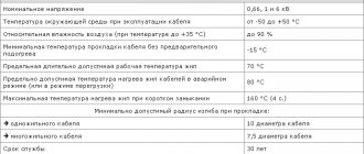
- Temperature regime - implies a normal operating temperature at which the wire will transmit electricity for a long time without losing its parameters;
- Permissible short-term heating - can occur in emergency modes, but should not exceed more than 8 hours of the annual load;
- Bending radius - determines the ability to bend the wire without compromising the mechanical strength of the insulation and its dielectric properties.
All technical characteristics compared for all brands are shown in the table below:
Table comparing characteristics of SIP brands
| Wire brand | SIP-1 | SIP-2 | SIP-3 | SIP-4 | SIP-5 |
| Number of current-carrying cores, pcs. | 1 ÷ 4 | 1 ÷ 4 | 1 | 2 — 4 | 2 — 4 |
| Core cross-section, mm2 | 16 ÷ 120 | 16 ÷ 120 | 35 ÷ 240 | 16 ÷ 120 | 16 ÷ 120 |
| Zero core, bearing | aluminum alloy (with steel cores) | aluminum alloy (with steel cores) | absent | absent | absent |
| Current-carrying core | aluminum | aluminum | aluminum alloy (with steel cores) | aluminum | aluminum |
| Voltage class, kV | 0.4 ÷ 1 | 0.4 ÷ 1 | 10 ÷ 35 | 0.4 ÷ 1 | 0.4 ÷ 1 |
| Core insulation type | thermoplastic polyethylene | light stabilized polyethylene | light stabilized polyethylene | thermoplastic polyethylene | light stabilized polyethylene |
| Operating temperature | -60оС ÷ +50оС | -60оС ÷ +50оС | -60оС ÷ +50оС | -60оС ÷ +50оС | -60оС ÷ +50оС |
| Permissible heating of cores during operation | +70оС | +90оС | +70оС | +90оС | +90оС |
| min wire bending radius | not less than 10 Ø | not less than 10 Ø | not less than 10 Ø | not less than 10 Ø | not less than 10 Ø |
| Life time | at least 40 years | at least 40 years | at least 40 years | at least 40 years | at least 40 years |
| Application | branches from overhead lines; — power supply to living quarters; - household construction laying along the walls of buildings and structures. | branches from overhead lines; — power supply to living quarters; - household construction laying along the walls of buildings and structures. | for installation of overhead lines with voltage 6-35 kV | branches from overhead lines; — power supply to living quarters; - household the buildings; — laying along the walls of buildings and structures. | branches from overhead lines; — power supply to living quarters; - household the buildings; — laying along the walls of buildings and structures. |
Permissible current loads of insulated wires for overhead transmission lines (SIP)
Nominal cross-section of main cores, mm 2
Permissible load current, A, no more
Permissible one-second short circuit current, kA, no more
To organize power power lines, overhead lighting lines, as well as to create a branch from the main electrical line to the entrance to residential premises in a temperate or cold climate zone, self-supporting insulating wires or SIPs are used. They are designed to operate with a voltage of 600/1000V inclusive and a nominal frequency of 50Hz. There are cables designed for voltages of 20 kV and 35 kV.
Laying conditions
Due to the fact that laying SIP does not require any special skills, it can be done either at home or by the enterprise’s own resources without the involvement of a specialized organization. Laying can be carried out both on supports and on structural elements of buildings and structures. As a rule, fastening to walls is much easier than on a free-standing support.
Therefore, consider the conditions for installing SIP wire on reinforced concrete supports:
- Since the self-supporting insulating wire has an insulated sheath, it is important to provide a suspension that prevents damage to the dielectric layer. To do this, plastic rollers, grips and thimbles are installed, along which the wire can move freely.
- During the installation process, it is forbidden to drag the SIP along the ground or tree branches, as these can damage its insulation.
- To join different sections of SIP, sealed piercing-type clamps are used. Thanks to this design, it is possible to tap a line from an existing one even under voltage.
- Before fixing it on the support, the SIP wire must be pulled out through the moving element (for SIP brands from 1 to 3 using a dynamometer until the normalized load is set). After stretching, it is fixed at the fixation points.
All fasteners are factory-made, so they can be found complete with self-supporting insulating wire, which will greatly simplify the task.
Rice. 6: Example of fastening a SIP wire to a support
Application, advantages and disadvantages
Due to the presence of insulation, SIP has a fairly wide scope of application. It is most often used to introduce electricity into a building, and thanks to the outer layer of insulation, additional measures and devices are not required when passing through walls. Also, a self-supporting insulating wire can be used for local wiring of networks throughout the facility or when connecting subscribers to the lines of an energy supply organization. A separate area of application for SIPs are trunk lines that provide power supply to entire villages or distribution substations.
Compared to other brands of cable and wire products, SIP has a number of advantages, namely:
- SIP wire has significantly lower reactance compared to bare wires;
- Does not require the installation of additional insulators at points of attachment to supports, walls and when entering the building due to the presence of an insulating layer;
- Takes up less space due to the fact that the wires are collected together;
- Not subject to corrosive destruction due to the presence of a protective layer;
- Not afraid of overlap of adjacent phases under strong wind loads;
- Makes it difficult to illegally take power by throwing on wires;
The disadvantages of SIP wire include the greater weight of a linear meter, which is why the spans need to be reduced and supports installed more often. As well as the need to arrange additional insulation for certain categories of premises and consumers.
Main manufacturers
To avoid troubles when purchasing a wire or cable, you should pay attention not only to the main parameters of the product, but also to its manufacturer. Since low-quality models may have a smaller cross-section, low dielectric resistance to various types of influence, etc. If you have already purchased a self-supporting insulating wire and are not sure of its quality, check whether the cross-section corresponds to that stated in the passport. How to determine the cross section at home is described in the corresponding article -.
If you are just going to buy SIP, pay attention to the following manufacturers:
- Kama cable;
- Rybinskcable;
- GC "Sevkabel"
- Moscabel.
Using wires from the above-mentioned factories, you can be sure that they comply with the declared characteristics.
How to choose a section?
The cross-section of the wire must correspond as much as possible to the power of the connected load. Wires that are too thin will have a higher resistance and, accordingly, become very hot, which leads to significant energy losses during transmission, and can also cause insulation destruction, short circuits and even a fire.
How to choose the right one? Regulatory documents and tables indicating voltage and current for different types of self-supporting insulated insulated wires will help you select a cable with the characteristics required by the consumer.
The key characteristic for choosing a wire is the current strength that can pass through it.
This indicator is different for different sections:
- 16 mm2 - 100 A;
- 25 mm2 – 130 A;
- 35 mm2 - 160 A;
- 50 mm2 - 195 A;
- 70 mm2 - 240 A;
- 95 mm2 - 300 A;
- 120 mm2 - 340 A;
- 150 mm2 - 380 A;
- 185 mm2 - 436 A;
- 240 mm2 - 515 A;
Proportionally, as the cross-sectional area increases, the maximum permissible current strength for which this wire is designed for the load also changes. In addition, wires of different sections can withstand different intensities and durations of heating during operation.
If the task is to supply electricity to the house using a sip pipe, it is important to choose the right option. Typically, a wire with a minimum cross-section of 16 mm2 is more than enough. Cables with a smaller cross-section are simply not produced, and larger ones are not needed for household energy consumption.
In a standard household power supply network, there are no significant overloads, and the ambient temperature does not go beyond - 50 - + 60 degrees.
