Technical and operational characteristics of SIP wires:
- Rated voltage 0.6/1.0 kV
- Ambient temperature from -50˚С to +50˚С
- Relative humidity 98%
- Minimum operating temperature for laying wire without heating -20°C
- Maximum permissible operating temperature of the cores +90˚С
- Maximum permissible heating temperature of the cores in emergency mode, as well as in overload mode: +130˚С
- Maximum core heating temperature during short circuit +250˚С
- Service life 40 years
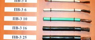
Let's look at the range of SIP wires and their characteristics.
Features and name decoding
Now we should consider the issue of wire marking. But before starting this issue with SIP wires, you should consider possible design features. Otherwise, you will simply get confused when decoding.
Design features of SIP brand wire
A SIP brand product may have several different types of cores. Each of them is marked differently, so let's figure out what they are called and what they are intended for. This issue is standardized by GOST 31946 - 2012.
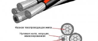
SIP wire design
- Let's start our conversation with the zero core. It can be load-bearing or without a load-bearing element. It can be used as a neutral (N), protective (PE) or neutral and protective (PEN) conductor. The cross-section of the zero load-bearing core can be from 25 mm2 to 95 mm2.
- There is also a so-called main vein. It is this circuit that is designed to transmit electric current, and it is this circuit that is usually used as a phase circuit. There can be from one to four main cores, and as the instructions provide, their cross-section can be from 16 to 240 mm2.
- In addition, some brands of SIP wires provide for the presence of auxiliary conductors. They can be of two types - intended for connecting lighting devices, or used as controls for connecting various measuring or relay devices.
SIP wire with auxiliary control core
- Auxiliary conductors are usually used for wires with a neutral conductor cross-section of at least 50 mm2. Their number can be from one to three. As for their cross-section, it all depends on the purpose. If these are conductors intended for connecting lighting devices, then their cross-section should be 16, 25 or 35 mm2. For control auxiliary cores this row is 1.5, 2.5 or 4 mm2.
SIP with auxiliary residential lighting
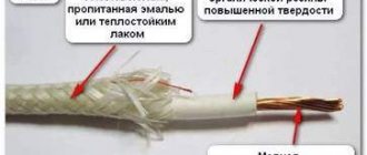
- This is all we have discussed regarding the cores and their purpose, but here it is worth mentioning one more issue - insulation. It can be regular, or it can be sealed. Its difference is that even if moisture gets under the sheath, it will not spread throughout the entire wire, as is the case with conventional insulation. This, of course, is a better solution, which is why the price of sealed products is slightly higher.
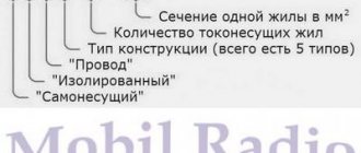
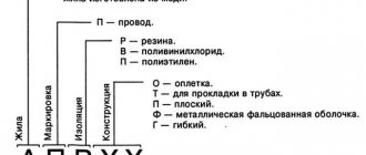
Explanation of the name
Now we are ready to consider the question: “How to determine the brand and cross-section of SIP wire by marking.” After all, this abbreviation is printed directly on the wire, and if you understand what it is about, you can easily read it on the product itself.
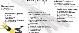
SIP wire marking
- First of all, its type of cable product is applied to its shell. In our case, this is SIP, which translates as: self-supporting insulated wire. Then its class is indicated through a hyphen. We met this question in the first section of our article.
- Then the markings contain a continuous set of numbers. But everything becomes clear if you know what it is. And this is a designation of the number and cross-section of cores. First of all, the quantity and through the multiplier sign of the cross-section of the main core are indicated, then through the plus sign the number and cross-section of the zero load-bearing core, and only then the number and cross-section of the auxiliary cores.
Note! SIP wire - and the classification speaks about this - does not always have auxiliary conductors. Therefore, the abbreviation can indicate only two types of wire - main and neutral. They are always there.
SIP wire designation option
- Further in the marking, a dash sign indicates the rated voltage for which the wire is intended. Sometimes two values can be indicated here separated by a slash. For example, 0.6/1. This means that the wire is designed for voltages of 660 or 1000V.
- And the last thing in the marking is the technical condition according to which the wire is made. Usually this is a set of numbers after the abbreviation TU.
SIP wire 2
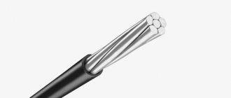
The self-supporting insulated wire SIP 2 is made with a zero load-bearing insulated conductor. The insulation of all cores is made of light-stable cross-linked polyethylene. Load-bearing core made of aluminum alloy. The number of current-carrying cores is from 1 to 4. All cores are round and multi-wire. The cores are twisted around the load-bearing wire to the right.
Imported analogues : AXKA-T, AsXSn (Poland), Torsada (France), AsXS.
The nominal values of the current-carrying cores of the SIP 1 and SIP 2 wires are in the table below:
| Nominal cross-section of phase conductor, mm2 | Number of wires in the core, pieces. | Outer diameter of the conductor, mm. | Electrical resistance of 1 kilometer of phase conductor to direct current, Ohm, no more |
| 16 | 1 | 4,35-4,45 | 1,910 |
| 16 | 7 | 4,60-5,10 | 1,910 |
| 25 | 7 | 5,7-6,1 | 1,200 |
| 35 | 7 | 6,7-7,1 | 0,868 |
| 50 | 7 | 7,85-8,35 | 0,641 |
| 70 | 7 | 9,45-9,95 | 0,443 |
| 95 | 7 | 11,1-11,7 | 0,320 |
| 95 | 19 | 11,0-12,0 | 0,320 |
| 120 | 19 | 12,5-13,1 | 0,253 |
| 150 | 19 | 14,0-14,5 | 0,206 |
Nominal values of the zero, supporting conductors of wires SIP 1 and SIP 2, in the table below:
| Nominal cross-section of load-bearing cores, mm2 | Permissible load current, A, no more | Permissible one-second short circuit current, kA, no more |
| 16 | 100 | 1.5 |
| 25 | 130 | 2.3 |
| 35 | 160 | 3.2 |
| 50 | 195 | 4.6 |
| 70 | 240 | 6.5 |
| 95 | 300 | 8.8 |
| 120 | 340 | 10.9 |
| 150 | 380 | 13.2 |
Classification of SIP type cable products
Let's start our conversation with such a question as the classification of SIP wire. In total, there are five main types of SIP brand products. Let's look at their main differences.
| Let's start with SIP - 1. This class of conductors includes all models that have a non-insulated load-bearing neutral core. At the same time, the phase, or as they are more correctly called, the main conductors of this type of wire are insulated. The same applies to auxiliary cores, if any. This option is intended for networks with voltages up to 1 kV. |
| The next possible class is SIP - 2. In general, it is almost identical to SIP - 1. Its main difference is the presence of insulation on the load-bearing zero core. It is also designed for networks with voltages up to 1 kV. |
| There is also such an option as SIP - 4. Its peculiarity is that it does not have a zero load-bearing core at all. In this regard, it can only be used as a descent from the main overhead line to end consumers. This is the wire that is usually used to connect to private households. It is also intended for networks with voltages up to 1 kV. |
| But the classification of SIP wires also offers models for higher voltage classes. For example, class SIP is 3, which is intended for voltages of 10 - 35 kV. Such a wire has one core with an extruded polymer film, the purpose of which is not to provide the proper level of wire insulation, but to reduce the likelihood of short circuits. That is, such insulation itself does not guarantee the absence of a short circuit when approaching another wire or grounded part, but only reduces this probability. |
| In addition, recently SIP class 7 wires have appeared on sale. They differ from the option discussed above only in the higher voltage class. They can be used for networks with voltages up to 110 kV. |
Wire SIP 3
Single-core self-supporting wire made of aluminum alloy. The core is multi-wire, round. Core insulation made of light-stable cross-linked polyethylene. When laying, the bending radius of the wire is 10 wire diameters
Analogs: PAS, SAX (Finland)
The permissible current loads of the wires and the permissible one-second short circuit current must correspond to those indicated in the table:
| Nominal cross-section of main cores, mm2 | Permissible load current, A, no more | Permissible one-second short circuit current, kA, no more |
| 35 | 200 | 3,0 |
| 50 | 245 | 4,3 |
| 70 | 310 | 6,0 |
| 95 | 370 | 8,2 |
| 120 | 430 | 10,3 |
| 150 | 485 | 12,9 |
Wire properties
Manufacturers produce SIP cables of different sections, designed for operation under appropriate loads. According to the standardization of GOST 52373 - 2005, this product is intended for use on power lines with a voltage not exceeding 35 kilovolts. Important: the standard specifies the maximum characteristics of SIP wires. If one of the parameters does not coincide with GOST, it is unacceptable to use such products. Main technical characteristics of SIP cables: 1. The highest temperature at which the product can be used. Depending on the brand of products, this indicator is from -50 to +50 C. 2. Installation of the wire. According to the instructions, installation of the SIP cable can be carried out at a temperature not lower than -20 °C.
3. The bending radius should not exceed 10 D. That is, the bend of the wire should not be more than 10 outer diameters of the wire. To calculate the exact indicator, you need to find out what cross-section the desired SIP cable has and multiply its indicator by 10. 4. Temperature limit. Critical mode 130 °C. 5. Permissible heating. During operation, the products can be heated up to +90, and in the event of a short circuit up to 250 °C. 6. Permissible load. The power depends on the cross-section of the SIP cable. So, for models of the 3rd type, the permissible load is 35 kV, and for the 1st, 2nd and 4th types - 0.66 per kV. 7. Product warranty – 5 years. 8. Service life – up to 50 years. Also, according to the technical characteristics of the SIP wire, the frequency in the network is 50 Hz.
Wire SIP 4
The conductors are aluminum, multi-wire, round. The number of cores is 2-4. The cores are compacted (compacted). The cross-section of the cores is 16-150 mm2. When laying, the permissible bending radius is 7.5 times the diameter of the wire
The permissible current loads of the wires and the permissible one-second short circuit current must correspond to those indicated in the table:
| Nominal cross-section of main cores, mm2 | Permissible load current, A, no more | Permissible one-second short circuit current, kA, no more |
| 35 | 200 | 3,0 |
| 50 | 245 | 4,3 |
| 70 | 310 | 6,0 |
| 95 | 370 | 8,2 |
| 120 | 430 | 10,3 |
| 150 | 485 | 12,9 |
Analogue: NFA2X; ALUS (Sweden).
Selecting a product with the required cross-section of phase conductors
The cross-section of the SIP cable of the required type depends on the rated current. To establish its value, you will need to draw up a diagram in which the following data must be indicated: 1. The length of all sections of the line. 2. The main load on each section. The resulting estimated value is compared with the indicators given in the table below. Based on this, you can make a decision on choosing the right type of product. In the table of cross-sections of SIP cables, the data is indicated for products -1, -2, -4:
The following example will help you more accurately calculate the cross-section of the SIP cable. In the case when the calculated current does not exceed 110 A, you can choose one of the proposed options for operation: 1. SIP 2. The cross-section of the product must be 25 mm². 2. SIP 1. Product cross-section – 35 mm². Experts advise giving preference to the first option: thanks to this, the line will be lighter, stronger and less susceptible to winds and precipitation.
Note: when selecting the right product, it is advisable to choose a SIP cable with a current-carrying core whose cross-section is larger than necessary. Then, during operation with possible increases in load, no unforeseen situations will occur.
Diameter of SIP wire cores
No wires for lighting:
| Number of cores and cross-section | Outer diameter of wire, mm |
| 1x16+1x25 | 17 |
| 3x16+1x25 | 22 |
| 3x25+1x35 | 26 |
| 3x35+1x50 | 30 |
| 3x50+1x50 | 33 |
| 3x50+1x70 | 35 |
| 3x70+1x70 | 38 |
| 3x70+1x95 | 41 |
| 3x95+1x70 | 43 |
| 3x95+1x95 | 44 |
| 3x120+1x95 | 47 |
| 3x150+1x95 | 49 |
| 4x25+1x25 | 22 |
| 4x25+1x35 |
With wires for lighting:
| Number of cores and cross-section | Outer diameter of wire, mm |
| 3x25+1x35+1x16 | 28 |
| 3х25+1х35+1х16(ozh) | 28 |
| 3x35+1x50+1x16 | 30 |
| 3x35+1x50+1x25 | 30 |
| 3x50+1x50+1x16 | 33 |
| 3x50+1x50+1x25 | 33 |
| 3x50+1x70+1x16 | 35 |
| 3x50+1x70+1x25 | 35 |
| 3x70+1x70+1x16 | 38 |
| 3x70+1x70+1x25 | 38 |
| 3x70+1x95+1x16 | 40 |
| 3x70+1x95+1x25 | 40 |
| 3x95+1x70+1x16 | 42 |
| 3x95+1x70+1x25 | 42 |
| 3x95+1x95+1x16 | 44 |
| 3x95+1x95+1x25 | 44 |
| 3x120+1x95+1x16 | 47 |
| 3x150+1x95+1x16 | 50 |
| 3x120+1x95+1x25 | 47 |
| 4x25+1x35+1x16 | 29 |
| 3x25+1x35+2x16 | 28 |
| 3x25+1x54.6+2x16 | 30 |
| 3x25+1x54.6+2x25 | 30 |
| 3x35+1x50+2x16 | 30 |
| 3x35+1x54.6+2x16 | 32 |
| 3x35+1x54.6+2x25 | 32 |
| 3x50+1x50+2x16 | 33 |
| 3x50+1x54.6+2x25 | 35 |
| 3x70+1x70+2x16 | 35 |
| 3x70+1x54.6+2x16 | 38 |
| 3x70+1x54.6+2x25 | 38 |
| 3x70+1x70+2x16 | 38 |
| 3x70+1x95+2x16 | 40 |
| 3x95+1x70+2x16 | 42 |
| 3x95+1x95+2x16 | 44 |
| 3x120+1x95+2x16 | 47 |
More articles
- The importance of calculating cable cross-section
- Recessed ceiling LED lights
- Cable channels of open wiring in residential and office premises
- NUM cable, description, application
- Flexible power cable KG: description, characteristics, purpose
- What cable trays are used in electrical installations?
- Terminal blocks for DIN rail: classification, photo
- Distribution box: description, types and types of distribution (junction) boxes
- Mounting boxes for electrical installation: classification and types
- Electrical trays: description, use, regulatory documents
Wire installation
The technology for installing SIP wires does not present any particular difficulties. Thanks to this, with the proper skill and free time, you can complete all the work yourself. But in order to install the SIP cable yourself, you must first coordinate the work with government services. In addition, before you begin installing the SIP wire to the house, you need to obtain permission from the company supplying electricity. In order to correctly carry out all work on connecting the line, you need to carefully study the recommendations of specialists. The step-by-step instructions for installing SIP wires say: 1. First of all, you need to select a product of the required cross-section. Most often, for installing SIP cables from a pole to a house, products with a cross-section of 15 mm are used. 2. If the extension line exceeds 25 m, you will need to install additional support and use a tensioner.
3. In the case when it is necessary to branch the SIP cable line, additional components will be needed for installation - a special clamp. With its help, you can make punctures on the pole in the right places. The advantages of using clamps include simplified installation - you will not need to strip the cable. Next, the installation of the SIP cable from the pole to the building is carried out according to the following plan: 1. Attach special fasteners to the support. Fasteners are necessary to ensure a strong connection. 2. Install the clamp. To do this, among the components for installing SIP wires there must be an anchor-type clamping device. It is a fitting with a bracket. 3. If wood was used for the construction of the building, according to the rules for installing SIP cables, additional insulation of the wire must be performed. To carry out wiring to stone or brick houses, there is no need to additionally insulate the wire. 4. Lead the wire 1 m into the building. 5. Make a branch inside the house. To correctly install SIP wires inside a building, you can watch a video. If necessary, a special coupling may be required to connect the cables.
Important detail: the most important condition for the rules for installing SIP cables to the house is that the work should only be carried out by those who have access to them. If there is none, it is best to contact specialists.
Disadvantages of SIP cables
The disadvantages of self-supporting wiring include:
- Increased product weight. Because of this, frequent installation of poles is required to prevent sagging wires. While installing wooden products in rural areas is not a problem, installing concrete supports in urban areas increases the cost of the work.
- The cost of SIP cables exceeds the price of ordinary wires of category A or AC.
- Lack of trained personnel and standards for wiring installation in regional sales companies. This drawback is gradually being eliminated as the qualifications of specialists improve and documentation for installation and maintenance is developed.
Advantages and disadvantages
Advantages:
- Easy to install. It is much easier to install than conventional wires without insulation. They do not require fastening to insulators.
- Reducing electricity theft. Connecting to lines with such wires requires certain qualifications; it is quite difficult and not accessible to everyone.
- No icing. The material from which SIP insulation is made does not retain wet snow and condensation. Ice formation on overhead lines is very small.
- Reduce the risk of electric shock. Thanks to insulation, the likelihood of electric shock during repair and maintenance of the line is sharply reduced. Many jobs can be done under voltage.
- Reduced installation and operating costs. Due to their design, the wires are less prone to breaks. Maintaining power lines with wires of this type is much cheaper. Wires of this type can be attached to the facades of houses. This allows the use of fewer supports.
- Low inductance. Such lines have very low reactance. Voltage and power losses in lines using SIPs are significantly less. Low inductance avoids interference and makes it possible to attach low-voltage and control cables to line supports.
Flaws:
- High price. Of course, such products are somewhat more expensive than bare wires, which are usually used for overhead lines.
- Lack of qualified specialists. Installation and maintenance of power transmission lines where these cables are used has its own characteristics. Such current-carrying products have appeared quite recently and have not yet become widespread. This is due to the lack of specialists who have the necessary skills and experience. In addition, domestic power supply systems are generally not suitable for a massive transition to current-carrying lines of self-supporting insulated wire.
The concept of SIP cable and its advantages
The name of the SIP wire stands for self-supporting insulated wire; its purpose is the transmission of electricity in power networks. Moreover, this type of cable can be used for installation and distribution only in those networks where the voltage does not exceed 35 kV.
The areas of application of this type of wire are as follows:
- street lighting (lanterns and signs);
- outdoor power lines in the air;
- power supply to private houses and garages.
For all of the above purposes, insulated and protected types of SIP cable can be used.
SIP wire has a number of advantages, such as:
- the electricity supply system when using a SIP wire can work even if it is dropped or connected;
- the wires are designed so that their surfaces prevent the freezing of snow and ice, and this improves and prolongs the operation of the electrical network even in cold weather;
- such products require minimal excavation, which is extremely convenient when laying networks in urban environments;
- the possibility of electricity theft or illegal connection is practically reduced to zero;
- wire cross-section can be found for any purpose;
- The insulation of SIP wires is so reliable that birds sitting on them are not able to suffer from electric shocks.
Application
SIP-1 - for mains of overhead power lines (OHT) and linear branches from overhead lines in air atmosphere of types I and II according to GOST 15150-69.
SIP-2 - for the mains of overhead power lines (OHT) and linear branches from overhead lines in the air atmosphere of types I and II according to GOST 15150-69, including on the coasts of the seas, salt lakes, in industrial areas and areas of saline sands.
SIP-3 - for overhead lines with a rated voltage of 10-35 kV in an air atmosphere of types II and III according to GOST 15150-69, including on the coasts of the seas, salt lakes, in industrial areas and areas of saline sand.
SIP-4, SIP-5 - for branches from overhead lines to the input and for laying along the walls of buildings and engineering structures in an air atmosphere of types II and III according to GOST 15150-69.