In most cases, each house or apartment is initially equipped with standard one-, two-, or three-key switches that control lighting from only one specific location. But this is extremely inconvenient, because how many times have you had to get out of bed to turn on the lighting in the room?
With modern electrical installations, pass-through switches have become more often used, which can turn off or turn on, for example, the lighting in a room at the entrance to the room and at the same time near the bed or, for example, on both sides of the corridor. How to do this? Very simple! To do this, it will be enough just to read this article.
What is a pass-through switch
A pass-through switch is a switch with several groups of contacts that is capable of simultaneously controlling a light source from several places. In the modern market of electrical installation materials, this device is represented by the following types:
- single-key with one input and 2 outputs;
- two-key with two inputs and 4 outputs;
- three-key with three inputs and 6 outputs;
- cross with two inputs and two outputs for controlling lighting from more than 3 places.
This type of device can be either a keyboard or touch or remote (control from a remote control). In most cases, standard key switches are used, however, in the case of installing a Smart Home system, it is better to install remote pass-through switches, which are controlled using a remote control or a special application for a smartphone.
Practical Application Examples
The digital device should be switched to dialing mode.
In this case, the same lamp can be controlled from each floor and, if desired, from the basement.
A pass-through switch allows you to close one of two circuits. How to make a pass-through switch from a regular one: work order. It is not always possible to quickly find a suitable model of a device that allows you to control lighting from two points at once. Connecting conductors using special WAGO clamps.
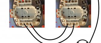
Let's look at the following circuit diagram: Three things have changed: From breakout box S1, switch S2 has two cables connected to it, which are used to power the other light switches. There are open type PV for connection with open wiring and closed type for connection with wiring running inside the walls. A diagram with two pass-through switches that allows control of two loads. The following video will help you understand in more detail the diagram for connecting a switch from two places: It clearly shows how to connect the wires in the junction box so that there are no difficulties during operation.
Electric lighting is an indispensable companion of any modern apartment. The first is used to connect a contact at the input, the second - at the output. To connect them, in the simplest case, you need two two-core cables. However, their functionality is very different.
Places of use In addition to the bedroom, similar situations can arise quite often. Before starting work, use a voltage tester to make sure that there is no electrical potential on the power cables, preferably on all terminals coming out of the box. The crossover device is connected between the feedthroughs. When choosing the appropriate option, you should buy a model with the same number of keys for each point. In such situations, it becomes necessary to control lighting from two places; it is for solving such problems that the so-called pass-through switches are designed.
Types of crossover and pass-through switches
With modern electrical installations, pass-through switches have become more often used, which can turn off or turn on, for example, the lighting in a room at the entrance to the room and at the same time near the bed or, for example, on both sides of the corridor. For the first case, socket boxes will be required for installation. It is also beneficial to use a similar scheme in small houses, the size of the floors. Electrical diagram for switching on a lamp from three places. An ordinary switch only closes and opens a circuit. Installing two ordinary switches in different places in the room will not allow you to control the lamp from two places at once.
Similar to switch S1, we connect the protective conductors with one connector and the neutral conductors with the help of a second connector. Conclusions and a useful video on the topic You can learn from the videos presented how the use of circuits for connecting pass-through switches from several places occurs in practice. Thanks to these jumpers, the phase to the lighting source can be supplied from either one or a second switch, which will allow you to turn on the lighting from several places. Such solutions are useful in large houses and small apartments. In order not to be mistaken about what kind of switch it is, you should familiarize yourself with the connection diagram, which is present on the switch body. Connection diagram for a two-key pass-through and crossover switch from two or more places.
Operating principle of a pass-through switch
In appearance, pass-through switches are identical to standard ones, but due to their design, their operating principle is significantly different.
So, when you press the key of a regular switch, the circuit simply closes or opens, but if you press the key of a pass-through switch, it opens one group of contacts and closes another.
Important! Unlike standard two-key (single-key) devices, pass-through switches can only work in pairs, since one and the second control the phase supply to the lighting device and if one of them is not in the circuit, then the phase wire will not flow to the lighting source, as a result the light will not light up.
Let us next consider what the connection diagram for a pass-through switch from 2 places should be, since this is considered the most common option for implementing lighting systems in houses, apartments or offices.
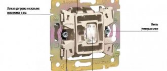
Design of a pass-through switch and difference from other types
Externally, a pass-through switch does not differ from a household device designed to control light. It is equipped with one, two or three movable keys, each of which has two independent fixed positions. The fundamental difference from conventional switching devices is in the design of the contact group. If a standard device has one pair of contacts for each key for closing and opening the circuit, then in a pass-through switch each movable panel controls a changeover contact group. In one position one circuit is closed, in the other - another. In fact, such a device is a switch.
Switch 2 has two contact groups that can be controlled independently. Three-key, respectively, three. To distinguish a walk-through device from a regular one, it is often marked in the form of arrows or a symbolic designation of a flight of stairs.
Two-key pass-through device with markings in the form of a ladder.
Important! Do not confuse pass-through switches with crossover switches. Such switching devices also have a system of switching contacts. The difference between crossover devices and two-key pass-through devices is that in the former, one key simultaneously controls two changeover contact groups. Another difference is in the internal layout. The normally open (normally open, NO) and normally closed (normally closed, NC) contacts of each pair of such a device are cross-connected. Such devices are also used in lighting control schemes from three or more points.
According to their design, pass-through devices are:
- invoices (for open and hidden wiring);
- built-in (for hidden wiring).
There are also touch switches, but they are more expensive. In addition, most users agree that they are less convenient.
Internal diagrams of conventional and pass-through switching devices.
Connection diagram for pass-through electrical switches for lighting control from 2 places
The connection diagram of the pass-through switch allows you to effectively control the lighting from 2 points when turning the lighting on and off:
- on a flight of stairs in a cottage;
- in a long corridor;
- in office premises;
- in walk-through rooms;
- in the bedroom (controlling the lighting circuits near the bed and at the entrance to the bedroom) and so on.
To answer the question: “how to connect a 2-key pass-through switch?” you need to understand the principle of its operation. Let's do this using the example of the photo presented above.
In this circuit, the neutral conductor (in most cases blue) from the distribution box is connected directly to the light source (light bulb). The phase wire (brown) from the distribution box comes to the 1st contact of pass-through switch No. 1, after which it goes from the first contact of switch No. 2 to the second end of the light bulb.
In this case, jumpers must be installed between contacts No. 2 and No. 2, as well as contacts No. 3 and No. 3 of pass-through switches No. 1 and No. 2 (these jumpers are connected in the junction box).
Thanks to these jumpers, the phase to the lighting source can be supplied from either one or a second switch, which will allow you to turn on the lighting from several places.
This is considered the simplest scheme because it allows you to control only one light source. In order, for example, to turn on the LED backlight and the main lighting separately, you need to use a two-key pass-through switch, the operating principle of which you will find in the next section.
General connection diagram
Such a switch can be used to control a lighting load (lamps) - one, two or three, depending on the number of keys.
Switching on the pass-through device for normal lighting control.
With this connection, one contact remains unused. But it is not economically feasible to use pass-through devices in this way - they are somewhat more expensive than standard ones. A common area of application for such devices is circuits for controlling light bulbs from different points.
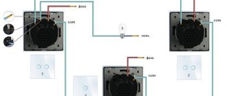
Independent lighting control from two points separated in space.
This connection allows each device to control turning the light bulb on and off, regardless of the state of the second. In practice, this principle can be applied, for example, when lighting long tunnels and corridors. At the beginning of the passage, you can turn on the lighting, and after walking to the exit, turn it off. The next person entering can again perform similar manipulations, regardless of the position of the switching devices and regardless of the direction of movement.
Control circuit for two-key pass-through switch
The principle of operation and connection diagram of a two-key pass-through switch is similar to a single-key switch, however, unlike the previous ones, these devices allow you to control lighting in several groups.
Let's consider the principle of operation of these devices according to the following photo:
This circuit contains:
- two double pass-through switches;
- power supply 220 V (phase and neutral);
- distribution box in which switching is performed;
- 2 groups of lighting circuits (for example, this could be a chandelier and LED lighting in a hall or room).
In this scheme, “0” (with correct blue color switching) is connected directly from the distribution box to one output of the 1st and 2nd lighting groups. Next, the phase wire (brown) comes into the distribution box and comes out of it and is connected to outputs No. 1 and No. 2 of pass-through switch No. 1.
Next, the outputs from pass-through switch No. 1 with numbers No. 3, 4, 5, 6 go into the distribution box, in which they are connected with similar outputs No. 3, 4, 5, 6. Then from outputs No. 1 and No. 2 of pass-through switch No. 2 the phase goes to the 1st and 2nd lighting groups and is connected to the second contact.
Purpose and types of pass-through switches
The essence of pass-through switches (PB) is the ability to turn light bulbs on and off independently from several places. Therefore, the operating scheme of this equipment implies the presence of at least two switches.
In terms of functionality, household pass-through switches can have from 1 to 3 keys, each of which is an adjustment mechanism independent of the others.
Backlight LEDs can be placed on the front panel of the pass-through switch for better visibility of the location of the keys in the dark
Different switch toggle switches control different lighting circuits, so DPVs are specifically designed for chandeliers or shades with two electrical circuits.
With an increase in lighting control points, the number of wires involved in the circuit increases sharply. Because of this, home wiring predominantly uses two or three pass-through switches per luminaire.
According to the interface, PV can be divided into:
- mechanical;
- sensory;
- remote.
The latter are rarely used due to impracticality, but you can find them in stores. Touch switches are good because any touch on them leads to alternately turning on or off the light. Mechanical keys are more familiar to humans and allow you to tactilely feel the change in the position of the toggle switch.
On the back panel of the pass-through switch there is a wire connection diagram that allows you to avoid confusion and connect them correctly
The visual design of the DPV can be very diverse. In electrical equipment stores you can choose pass-through switches of the desired color, shape and design. The external parameters of the device do not affect its functionality.
How to install in a junction box
In order for a double pass-through switch or lighting devices to perform their function for many years, the switching process must be approached thoroughly.
Often, due to negligence or lack of extensive experience in performing electrical work, twists can be found in junction boxes. However, this is a serious violation, since over time, contact may be lost in these twists, as a result of which the wires will begin to heat up, burn out, and a fire will occur. It is also strictly forbidden to connect copper and aluminum wires without any interlayer.
For reliable connection of cables and wires in junction boxes, 3 methods are recommended:
- Soldering contacts.
- Welding of conductors using special transformers.
- Connecting conductors using special clamps (WAGO).
Mixed compositional schemes
In the practice of designing buildings, it is necessary to use more complex schemes, which are various combinations of those listed and briefly described above. Most often, their use is determined by special requirements of an individual or technological nature. It is precisely such compositional schemes that are usually called mixed.
In order to properly organize the internal space of a building, it is important to choose the most suitable compositional scheme. In this case, the designer is required to identify which of them will be the most optimal in order to use all the internal volumes of the structure in accordance with their functional purpose.
Basic recommendations for installing two-key pass-through switches
When installing both standard and two-key pass-through switches, it is recommended:
- The placement height from the floor level should be 90 cm.
- The distance from the door or window opening to the pass-through switch must be at least 15 cm.
- Distribution boxes with switching must be located in a visible place and at the same time they must be placed at a distance of 15–30 cm from the ceiling level.
- For installation of pass-through switches, it is recommended to use a 3-core flexible cable with a cross-section of 1.5 mm² (VVGng, PVSng, ShVVP, and so on).
- Cable and wire products must be laid in corrugation, in grooves or cable channels.
- All metal surfaces of lamps must be grounded.
Design and working diagram of the DPV
A pass-through switch is more accurately called a switch because it does not have a specific position at which voltage is supplied to the lighting fixture. The key markings do not have standard “on”/“off” inscriptions or stick and oval icons. Typically, the switch has only two multidirectional arrows, which indicate the dual purpose of the toggle switch.
If there are doubts about the correctness of the electrical circuits, they can be checked with a multimeter by connecting a regular battery to the input of the junction box
Unlike a standard two-key switch, which has one input and two outputs, the DPV is a symbiosis of two independent single-key circuits located in one housing. A double pass-through switch provides separate control of two lighting lines. Each electrical circuit can be closed independently from any of 2-3 devices.
It is convenient to consider the operating diagram of the DPV with placement in two places using the example of one pair of toggle switches. One power wire goes to the switch from the distribution box, and two come out of it. Depending on the position of the key, some of the wires are always energized. Both wires go to the second switch, and one wire goes from it to the lighting fixture.
Thus, switching any key opens one circuit and closes another. As a result of this action, the switched off light comes on, and the switched on one goes out.
The complexity of the electrical circuit of the pass-through switch does not affect its reliability. The likelihood of such a system breaking down if safety precautions are followed is minimal.
The above example shows that three wires should go from each toggle switch to the distribution box, that is, a total of six wires from each DPV. And for three-zone control, as many as eight wires fit into the central transition switch. All this must be taken into account when planning electrical wiring in the house.
Option #1 - two-zone placement
It is advisable to install the DPV before interior finishing of the room.
After all, the installation and connection diagram of a two-key pass-through switch assumes the presence of as many as four grooves:
- One from the power source to the distribution box.
- Two from the distribution box to the PV.
- One from the box to the lighting sources.
After gating the walls, you need to decide on the number of cables needed and the number of cores in them.
After plastering the walls, it is important to remember the location of all electrical wires so that when drilling holes in the walls you do not stumble upon them
It is necessary to lay two three-wire or three two-wire wires between the distribution box and the first DPV. Two wires will be used to supply voltage to the switch, and the remaining four will follow through the distribution box to the second switching device.
Three two-wire wires are laid in the groove to the second DPV. Two of the wires go to the lighting fixtures, and the remaining four go to the first switch.
One or two wires with “zero” can be connected to lighting fixtures. The specific number of cores depends on the power consumption and the convenience of parallel connection of the lamps. A regular two-core power wire fits into the junction box itself.
The main task when installing PV is to correctly connect the cables in the junction box. It must be large enough to accommodate a minimum of 16 wires. If you do the work slowly and test all connections with a multimeter, you will end up with a workable electrical circuit.
Option #2 - three-zone placement
Independent three-zone control of two lighting circuits differs from the two-zone system discussed above by the presence of a special cross switch. It is placed exclusively in the middle of the electrical circuit, although it has the same functionality as the other two DPVs.
To prevent multi-level wiring from interfering with further repairs, they try to conduct it at a distance of 15-20 cm below the ceiling level
The double crossover switch has an unusual design containing a bypass contact. One of the wires coming from the first switch is always connected to it, regardless of the position of the toggle switch. It closes in both positions of the cross-circuit breaker, which ensures the functioning of the entire electrical circuit.
The middle cross switch is not interchangeable with the end devices. An infinite number of such intermediate devices can be added to the scheme under consideration, increasing the number of control zones for turning on/off the light in the room. But the complication of the circuit entails an increase in the number of necessary wires and grooves in the walls, which will not add joy to the installation of wiring yourself.
As the number of control zones increases, the wiring complexity does not increase greatly, but the number of switches must be taken into account when choosing the size of the junction box
To install an additional DPV, it will be necessary to make another groove from the distribution box for laying the cable. It needs to fit as many as 8 wires: 4 going from the first switch and 4 going to the second.
If the electrical installation is done by professionals and there is a financial opportunity to install all the switches, then using a DPS with three-zone control for this is an excellent option.
conclusions
Pass-through single-key and two-key switches are modern switches that allow you to organize control of one or more lighting sources from different places in one or adjacent rooms.
As can be seen from the above information and photos, we can say that despite the design (single-key or pass-through two-key switch, the connection diagram for 2 sources) is very easy to install and allows you to effectively control the lighting in a huge cottage, a large retail space or in industrial buildings.
To connect these devices it will be enough:
- two pass-through switches with 2 keys or two single-key switches;
- distribution box;
- flexible cable with three cores.
Practical implementation of a scheme with two pass-through devices
The specified connection diagram for a double pass-through switch can be implemented in practice in various ways. The choice depends on local conditions and is made for reasons of ease of installation and economic reasons.
Connection via junction box
If the distribution box to which the pass-through two-key switch is supposed to be connected is located approximately halfway between the input and output of the pass-through, the following wiring diagram can be used:
Connection of two double feed-through switching elements via a distribution box.
In this case you will need a cable:
- five-wire for connecting the first switch;
- six-wire for connecting a second switching device (its changeover contacts are connected separately and an additional conductor is required).
The cables are laid from the installation site of the switches to the distribution box, where the wires are disconnected. Obviously, the circuit turns out to be quite cumbersome, and during installation it is necessary to carefully monitor the correct connection. The use of cables with multi-colored core insulation or with numbering printed along the entire length of the conductors will significantly facilitate the work, minimize the likelihood of errors and avoid the tedious and labor-intensive part of the work of testing conductors. To perform installation correctly, you need to focus on the internal diagram of the device, printed on the back side.
Connection diagram on the back of the device.
Another marking option is symbolic:
- L1 or L2 – changeover contacts for the first and second groups, respectively;
- An arrow with a number indicates normally open and normally closed contacts.
Symbolic marking of two contact groups.
To avoid mistakes, you can draw a sketch of the circuit on a piece of paper (using colored markers) or on a computer with the correct color markings. If the switch terminals are marked with symbols, they must also be marked on the sketch. This will prevent you from getting confused in the conclusions. The connected circuit can be marked in the figure. This will further reduce the likelihood of error.
This connection option involves many connections of conductors. It is difficult to lay such a number of wires and connectors in a standard junction box with a diameter of 60 mm. It is advisable to purchase a box of increased diameter.
This scheme is used in most cases in conjunction with hidden wiring. Its installation involves gating the walls and creating recesses for installing socket boxes for switches - devices with hidden installation are usually chosen.
The cable cross-section is selected based on the load power. Many years of experience in arranging lighting systems allows us to say that a copper cable with a cross-section of 1.5 sq. mm is sufficient for almost any case. And the widespread use of LED lighting does not give rise to an increase in this value. But in this case, one more parameter is important. The length of electrical lines can be significant, and the voltage drop across the wiring can be significant. It is better to check this parameter before starting installation. The most convenient way to do this is with online calculators. If less than 95% of the input voltage reaches consumers, the cross-section must be increased by one step and checked for losses again.
Video lesson: Details about lighting control from 2 places.
Pass-through switch for 3 places
Is it possible to connect more switches to control the lighting of one lamp? When using only conventional step switches, it is impossible to control the lamp from more than two places. For even more places, you need to buy cross switches, which are placed between the ladder switches, as shown in the diagram.
Circuit drawing
- The first stage is preparing the wires and places for connection. Typically a pair of cables is used, with at least three cores.
- The wires need to be shortened. The wires should protrude at least 60-80 millimeters from the edge of the socket box.
- The insulation and braiding from the ends of the cores is completely removed. A distance of 10-14 millimeters will be sufficient.
- After this, you can begin connecting the wires to the switch. On the back side there are always terminals with their own markings, which makes installation easier.
- The wires are laid in the socket box as compactly as possible. Finally, we move on to the switch mechanism.
- We align the system strictly on a horizontal plane. The mounting screws must be fully tightened. It is best to use the elements included in the kit for fastening.
- A special frame is installed.
- To do this, we use a special plastic clamp. It must be inserted into the grooves of the caliper.
- All that remains is to install three or two keys.
How do stair switches work?
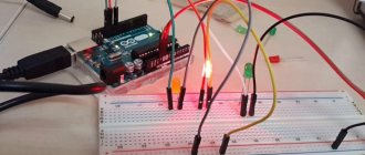
A simplified diagram looks like this (take a closer look at the animation).
- We provide electrical potential through the phase wire (L).
- The switches are connected by two brown and gray wires (in the diagram).
- The light bulb lights up when the electric current from the L-wire reaches the lamp.
- The circuit can be interrupted independently using either ladder switch S1 or S2.
- With the help of a staircase switch, they do not completely break the circuit, but choose which electric potential is transferred to the second switch.
Thus, a pass-through switch has one more contact compared to a single switch. In the usual one there are 2, but here there are 3 terminals for connecting wires.
The following diagram has more in common with reality. So let's see what's happening here:
- The power cord is connected to switch S1.
- We connect the neutral (N) and protective (PE) wires outside the circuit breakers using electrical connectors. The conductor protection connector is connected to the lamp body (or PE terminal), the neutral wire to the N terminal.
- The power phase conductor (L) is connected to terminal No. 1 of switch S1. After this operation and voltage application, the electric potential will be applied to either terminal No. 2 or terminal No. 3 of switch S1.
- Therefore, the 220V electric current at terminals 2 or 3 will reach switch S2.
- If switches S1 and S2 are in the same positions, an electrical potential will appear at terminal No. 1 of switch S2 and the light will turn on.
In order for the light bulb to light up, it is extremely important that the circuit is not interrupted, starting from the 220 V phase supply wire (L) and ending with the lamp.
Some nuances when connecting the device
Inside the junction box, when working with two-key switches, you need twice as much not only the wires themselves, but also their connections. It is better to buy special terminal blocks so that serious problems do not arise when organizing them. Then it will be impossible to get confused in the twists. A marker and tape will help indicate important details, then the process will not take much time.
When installing three or more devices, two different circuits responsible for lighting are powered. Therefore, it is better to use a serial circuit for connection. First we mark and install one chain, and then the second.