Every house has switches, and more than one. We have all become accustomed to these small devices and consider them an integral part of our everyday life. It may seem that they are all designed the same and are extremely easy to install. However, this is not at all true - the devices are very diverse.
Agree, it would be a good idea for any home craftsman to know which model is best to use and how to install the light switch so that the device works flawlessly.
The article is devoted to solving these questions. We will outline the operational features of different switches, and also provide detailed instructions for installing open, hidden and walk-through models.
Wiring: open or hidden option
Despite the fact that installing a switch may seem like a very simple matter, there are a large number of nuances that a novice electrician must know.
First you need to decide on the type of wiring.
Open wiring is still used in everyday life. It is especially loved by designers who create interiors in retro or loft style.
Electrical wiring is an essential element present in every home.
There are two types of it:
- Open . The wires are laid on top of the wall. They can be secured with decorative rollers or covered with plastic cable ducts.
- Hidden . The wire is laid inside the wall. To do this, channels are cut into its surface into which the cable is laid. After installation, the grooves are sealed with mortar.
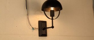
Each type of wiring uses a different type of switch. For an open system, choose overhead models that are placed directly on the wall. They are easily recognizable because they are very visible on the surface.
This type of switch was the first to appear and has changed little over the past decades. For closed wiring, internal or built-in models are used.
Image gallery
Photo from
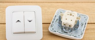
Switch-socket block for open wiring
Benefits of installing external switches
Switches for hidden electrical wiring
Disadvantages of hidden wiring switches
They are installed in a recess that is previously prepared in the wall. The dimensions of the hole are selected depending on the dimensions of the switch. It is attached inside the recess using special spacer legs.
There is another type of built-in devices - with mounting plates. This option is more convenient to install. After installation, the internal switches practically do not protrude above the wall plane.
Getting acquainted with the rules and preparing materials
First of all, everyone, and especially beginners, need to remember the basic safety rules when manipulating electricity:
- Always turn off the electricity and use a multimeter or an indicator screwdriver to make sure that there is no electricity directly at the work site.
- Do not touch exposed veins with your hands.
- Study the color and other markings of the wires, carefully ensure that the neutral wire is connected to the neutral, ground to ground, and phase to phase. Otherwise, a short circuit may occur and the wiring may catch fire.
- Choose high-quality electrical components and consumables, again do not use old switches and wires.
- To connect wires, use soldering, terminals, connecting blocks, and not twisting or insulating tape.
- Calculate the maximum voltage on the wires and, in connection with this parameter, select the cross-sectional diameter and other operational characteristics of the conductor.
- Familiarize yourself with the installation diagram of the switch of the selected type (with one, two or three keys).
Read here! GSM socket - purpose, main types, operating principle and connection features. Rating of the best models of 2020!
It is also necessary to prepare all the necessary tools and materials in advance. So, to install the electrical wiring of a switch, you will need a drill or hammer drill, a special attachment for making a hole, a multimeter, screwdrivers (including an indicator screwdriver), a spatula, pliers, a knife, a two-core wire, a socket box, a switch, putty or plaster mortar.
Attention! When purchasing a new switch, you must purchase a socket box suitable for the model, which differs from the standard iron versions of the old model in its compact size and is made of special non-flammable plastic.
Switch wire switching method
Before you begin installing the switch, you need to know that the internal fastenings of the wires in the device may be different. Two switching methods are used.
Screw type clamp
The screw type contact is tightened with a screwdriver. First, approximately 2 cm of the wire is cleared of insulation, then it is located under the terminal and secured. It is extremely important that not a millimeter of insulation remains under the terminal, otherwise it will begin to melt, which is very dangerous.
Screw-type clamps are optimally used for aluminum wires, which tend to heat up and become deformed. To restore functionality, it will be enough to tighten the contact (+)
This connection is especially good for aluminum wires. They heat up during operation, which eventually leads to deformation. In this case, the contact begins to heat up and spark.
To solve the problem, it will be enough to tighten the screw. The wires, sandwiched between two flat contact plates, will “fall into place” and the device will operate without heating or sparking.
Non-screw type clamp
Represents contact with the pressure plate. Equipped with a special button that adjusts the position of the plate. The wire is stripped of 1 cm of insulation, after which it is inserted into the contact hole and clamped. The whole procedure is very quick and easy.
The non-screw clamp is extremely easy to install, which is why experts recommend that novice electricians work with terminals of this type
The design of the terminal ensures high reliability of the resulting connection. Non-screw terminals are best used for copper wiring.
It must be admitted that screw and non-screw clamps provide approximately the same reliability and quality of connections. However, the second option is easier to install. It is this that experienced specialists recommend using for novice electricians.
Why “phase” and not “zero”?
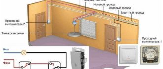
We are close to answering the question of whether zero or phase goes to the switch and why. The switch opens the section of the network in which the light bulb operates. And in simple switches it interrupts only one of the wires that passes through it. The second wire remains powered directly to the lamp. If in your case a zero is passed through the switch, then a phase is permanently connected directly to the chandelier, which means that even with a simple replacement of the light bulb, the device can shock you.
If the switch opens the phase, then zero goes directly to the chandelier from the box. This means that if the switch is in the open (off) state, the phase is no longer supplied to the device, since it is interrupted by the switch itself, and replacing the lamp will be safe.
Main types of switches
The time has long passed when all models were approximately the same and differed only in appearance. Today, the manufacturer produces a variety of types of switches. Based on the type of switching on/off, all of them can be divided into several groups.
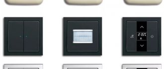
No. 1: Keyboard type devices
Very simple and reliable design. The basis of the device is a swinging mechanism, which is pressed by a spring. When you press a key, it closes a contact, which turns the electrical device on or off.
For the convenience of consumers, one, two and three-key switches are available. This makes it possible to control not only one, but several lamps at once.
No. 2: Switches or changeover switches
Externally, these devices are indistinguishable from their keyboard counterparts, but their operating principle is completely different. When you press a key, the devices open one electrical circuit and transfer the contact to another.
This allows simultaneous control of lighting from two, three or even more places. Complex circuits that involve more than two switches are supplemented with crossover elements.
Dimmers not only turn on the lighting, but also regulate its intensity. There are also multifunctional types of devices that can simulate presence, operate on a timer, and much more.
#3: Dimmers or Light Intensity Controllers
A switch that allows you to adjust the lighting intensity. The external panel of such a device is equipped with keys, a rotating button or infrared sensors.
The latter option assumes that the device can receive signals from the remote control. Complex dimmers can perform several functions: activate dimming mode, simulate presence, turn off lights at a specified time.
The criteria for choosing a dimmable switch are described in this article.
No. 4: Switches with built-in motion sensor
Devices react to movement. The appearance of people is registered by a sensor that activates the lighting and turns it off if there is no movement. To operate the switch, an infrared sensor is used, which is capable of analyzing the intensity of infrared radiation and distinguishing a person from other objects.
Multifunctional switches with a motion sensor can not only turn on lighting fixtures, but also activate video cameras, sirens, etc.
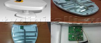
No. 5: Touch-type devices
Turn the lighting off/on by lightly touching the sensor. Varieties are available that are triggered when a hand is passed near their body. The main difference between touch switches and traditional analogues is the presence of microcircuits.
This eliminates the risk of a short circuit, which significantly increases the service life of both the switch itself and the lighting fixture.
There are many types of switches. Illuminated models are designed to facilitate orientation in dark rooms
Connection rules and diagrams
The switch is installed according to a specific scheme. It depends on the type of device. The diagram and procedure are described in the instructions.
Single-key
This is the basic algorithm for installing a surface-mounted switch.
- The electricity on this circuit is turned off.
- in the socket box for the cable . Cover it with alabaster and place it in the hole. The wire is pulled through the hole. Alabaster hardens in 2 hours, after which installation continues.
- Using a flat-head screwdriver, disconnect the switch frame and the key. Unscrew 2 screws diagonally and pull out the mechanism.
- Unscrew the contact screws . One of the contacts is intended for phase, the second - for zero. Each contact has 2 holes for cable connection.
- The power cable is divided into cores . Strip the ends to 1 cm.
- Connect the neutral wires from the power cable and from the wire to the lamp using a terminal or solder
- Insert the phase from the box into the desired contact . It is designated by the letter L. The core must fit between the pressure plates. Tighten the contact screw and check the wire: it should hold well and not wobble.
- The wire from the lamp is inserted into the contact marked either 1 or an arrow. They are tightening it up. The bare area should extend 1–2 mm from the contact.
- Unscrew the screws of the spacer mechanism - next to the legs. Insert the device into the socket. Align and tighten the spacer screws.
- Install the decorative frame and screw in the screws diagonally. Then the key or button is latched.
In expensive models, the cores are simply inserted into the socket, and the clamps are triggered automatically. There is no need to tighten the screws.
Two- and three-key
The two-button version differs only in the number of wires. There are 3 pins on the back wall of the case. One is intended for the input phase, it is slightly spaced out. 2 adjacent holes are designed for 2 outgoing phases for 2 groups of lamps. The connection diagram is exactly the same as for the single-key one.
In the three-key model, there are 3 holes next to each other for 3 outgoing phases.
Contactless
Installing a touch switch is not much different. Be sure to remove the glass touch panel from the device. Then a special socket box is installed and the switching mechanism is inserted. The wires from the junction box and the light bulb are fixed into the connectors and tightened with screws – L and L1.
Fix the device itself with screws and snap the front panel into place.
Backlit
In this version, the key or switch button is equipped with LED backlighting. It consumes very little energy, but works when the main circuit is closed. Along with the diode, a resistor appears in the circuit. It reduces the voltage to a minimum so that only the diode can burn.
The connection itself is performed using the same algorithm. The easiest way is to use the connection diagram, which is shown on the back of such a switch. The user needs to insert the desired wire into the desired terminal. Connecting a light bulb through a switch is similar.
With grounding
Such models are rare, since according to recommendations the closing loop should not have interruptions along its entire length. But if the switch, contrary to the rules, is installed in the bathroom, they resort to this method. It is not the device itself that is grounded, but a metal part of the electrical equipment, for example, the mounting substrate, which is often made of steel. In this case, if a current leak or short circuit occurs, the RCD will trip and turn off the circuit.
How to choose the “right” place for the switch
Choosing a place to install the switch is a personal matter for each owner. However, there is a set of industry requirements that regulate this issue. This is due to the fact that laying electrical wiring is quite an expensive undertaking and redoing it every time is expensive and too troublesome.
Experts recommend installing all switches in the house at the same height and the switching position should be common for all.
The devices are usually mounted at the height of door handles, which correlates well with the development of muscle memory. Thus, when entering a room, a person presses a key automatically, without even noticing it.
Another important point: the switch in the room must be positioned so that there is a distance of about 15-20 cm between it and the doorway. This way a person can grab the door handle with one hand and press the key with the other.
For living rooms, it is customary to install switches only indoors. For common areas, such as bathrooms, closets or corridors, switches located outside the room are most often used.
If there are small children in the house, you should not “lift” the switches up. The restless period when the baby will “play around” with the light will pass very quickly, and the inconvenience from the location of the switches will remain for a long time.
The design of the switch is extremely simple. Its main elements: mechanism on the mounting plate, keys and decorative protective panel
Choosing an installation location
The installation location of any electric light switch is regulated by the Electrical Installation Rules (PUE). Clause 7.1.51 recommends installing these electrical appliances at a height of 1 m at the entrance to the room from the side of the door handle. There are no specific instructions on the height and location of switching devices in apartments and houses, except for one thing - the distance to the gas supply pipes should be at least 50 cm. Otherwise, you can be guided by considerations of personal convenience (in many cases, 1 m from the floor is just the most comfortable). But if we are talking about children's institutions, then the Rules are strict - the switch must be installed at a height of at least 1.8 m.
Important! Clause 7.1.52 of the PUE prohibits the installation of lighting switches in wet rooms (bathrooms, showers, etc.). An exception is washbasins and zones 1 and 2 according to GOST R 50571.7.701-2013. They can be used to install switches under the ceiling with a cord.
| Zone 0 | Zone 1 | Zone 2 | Zone 3 |
| Inside the bath and shower | The height boundaries are the floor below, the top is a plane parallel to the floor at a height of 2.25 m. | ||
| Vertically - the outer vertical plane of the bathtub or shower tray or the vertical plane at a distance of 0.60 m from the shower spray (for a shower without a tray). | Vertically - the outer surface of zone 1 and a vertical plane parallel to it at a distance of 0.60 m. | Vertically - the outer surface of zone 2 and a vertical plane parallel to it at a distance of 2.40 m. | |
Surface Mount Switch Installation Procedure
Such devices are used for open wiring and where for some reason it is impossible to make a hidden connection.
Let's look at the installation procedure using the example of a fully factory-assembled single-key switch. To connect it, you need to turn off the power supply to the apartment, and then perform the following operations sequentially.
Step 1: Disassemble the device
We take a slotted screwdriver, very carefully lift the device key and remove it. After this, just as carefully, trying not to damage it, remove the protective decorative cover. All we have to do is disconnect the working mechanism from the socket plate. Let's carry out this operation.
Step 2: Design the installation location
The manufacturer must make holes on the base plate for securing the device. They need to be marked on the wall. To do this, take the socket box, apply it to the surface and mark the line of the top edge with a pencil.
Using a level, we check that it is horizontal, otherwise we will not be able to install the switch evenly. After this, we again apply the plate to the wall and mark the attachment points.
Step 3: Install the socket plate
Further actions depend on the material from which the wall is made. If it is soft wood, fasten the base with galvanized screws. If the base is made of harder materials, you will have to drill holes in it.
We try to do all the work accurately so that we don’t have to make additional holes. We securely fasten the plate to the wall.
The last stage of mounting a surface-mounted switch is the installation of a protective decorative case and a key. After this, the device can be used
Step 4: Connect the wires
We determine the type of contact switching and cut and strip the wires in strict accordance with it. Be sure to remove all insulation so that it does not subsequently melt and cause problems with the operation of the device.
We check that the wires reach the terminals as accurately as possible; it is undesirable for excess wires to remain. In accordance with the markings and color of the wires, we connect them to the required contacts.
Step 5: Assembling the device
First we need to make sure that the wires are connected correctly, for which we test them with a multimeter screwdriver or other device. Having found out that everything is assembled correctly, we take the switch mechanism and install it in place.
Then we return the protective decorative cover and, last of all, snap the key into place. We check the operation of the device.
Design and purpose of switches
A switch is a simple mechanical (less often electronic) device for contact closing/opening an electrical circuit to turn on/off lighting fixtures.
We will touch on the design features and installation of the simplest models - single-key switches.
They consist of 4 main parts:
- working unit - metal base with contacts and push-button drive;
- fasteners - legs or antennae made of metal connected to a metal plate;
- decorative design - panels or frames;
- dynamic part - plastic key.
Some parts, mainly internal ones, are made of metal, such as galvanized steel; external decorative trim is usually made of safe plastic. Ceramic elements are also available that can withstand loads of up to 32 A, while plastic is rated for 16 A.
Reasons for installing a single key switch include:
The external and internal structure depends on several factors, for example, functional tasks or potential load. As an additional device, some models have an LED that provides external illumination.
The design of a simple switch with one key: 1 – a key with which the mechanism is activated; 2 – decorative frame; 3 – working part, which contains the electrical mechanism
Switches are installed in all rooms where there are any lighting devices that are not equipped with a power cable (for example, it is not needed for floor lamps or table lamps).
These are most often ceiling or wall lamps, chandeliers, and complex lighting systems.
When choosing devices for rooms with high humidity levels, you should pay attention to such an indicator as the level of protection: for a bedroom or living room, IP 20 is enough, for a bathroom or kitchen - IP 40, for outdoor (street) installation - IP 55
Connecting a pass-through switch
To correctly install a rocker light switch, you need to accurately understand the principle of its operation. In the simplest case, the device, when you press a key, will open one circuit and close another.
On the back of switches of this type, the manufacturer always shows a diagram of the device’s operation. Let's consider the installation procedure for the simplest single-key pass-through switch.
For installation, we will need a three-core cable, each of the cores of which will have a factory color marking. Be sure to turn off the electricity before starting work.
We sequentially perform the following operations:
- On the pass-through switch we determine the common terminal.
- We bring out the phase conductor to the switch that is located closer to the distribution box and connect it to the common terminal.
- We connect the remaining two wires to the output terminals of the pass-through switch. At the same time, be sure to remember what color wire is connected to which terminal.
- In the distribution box we connect the phase from the lamp with the phase wire of the second pass-through switch.
- Guided by the color of the braid, we connect the two remaining wires with wires of similar color from the first switch.
Afterwards, we find the grounding and neutral wires in the distribution box and connect them with similar cables going to the lamp.
The figure shows the installation diagram of a simple single-key rocker switch (+)
We carry out all the twisting very carefully, if necessary we tin it and properly insulate all exposed sections of the wires. It is strongly not recommended to connect copper and aluminum wires together.
Next, we proceed to install the pass-through switch, which will be similar to the procedures described above. We disassemble the device, connect the wires to it in accordance with the diagram, put the mechanism in place and fix it.
Reinstall the protective panel and key. Now you can start checking the functionality of the assembled circuit. Make sure that both switches can control the lamp. That is, each device can turn the lamp off or on, regardless of the position of the other device.
Each switching of the pass-through switch must turn the lamp off/on. If not, you should look for and correct the error.
A more complex variation of a single-key rocker switch is a two-key device. Essentially, these are two single transition devices assembled in a common housing.
This design allows you to control several lamps at once. The device is connected with a three or six-wire wire.
Step-by-step installation of household switches
The quality of installation is initially determined by the use of tools. To install switching devices you will need:
- two Phillips screwdrivers (one smaller, the other more powerful);
- wire cutters for shortening wires;
- indicator screwdriver to check the presence of voltage;
- installer's knife for stripping wires (even better - a special insulation stripper).
You may also need other small tools.
Step 1 - Power Off
The first step in installing a switch (and dismantling the old one) is to relieve the voltage. We need to find where the voltage comes from to the switching element and to the entire lighting system. This is usually a switchboard. There is a diagram in it, or each machine is supplied with the signature of the consumer.
Switchboard with diagram.
After turning off the corresponding machine, you need to check the voltage directly at the workplace - there may be an error in the markings in the switchboard.
Step 2 - Checking the phasing
If you are replacing an old switching device with a new one, then to check the phasing you need to remove the switch keys and gain access to its terminals. For old-style devices, you need to remove the front panel by unscrewing the screws.
A device from previous years with self-tapping screws on the front panel.
Next, you should briefly turn on the voltage from the distribution board, and use an indicator screwdriver to check the presence of voltage at the input terminal. In most cases, the power wire is supplied from below.
Voltage check points.
If you are installing a new lighting system, you need to strip the supply wire with a mechanic's knife or an insulation stripper. After briefly applying power, make sure that nothing is messed up. In both cases, if a phase wire is connected to the installation site, there will be a lot of work to redo the installation. This is especially true for hidden wiring.
Step 3 — Dismantling the old device
Next, you need to turn off the voltage supplied to check the phasing and remove the old switch. To do this, you will need to loosen the terminals and unscrew the fasteners (if the device is equipped with expansion petals, they also need to be loosened as much as possible). After this, the device must be carefully removed.
The screws are responsible for releasing the fastening tabs.
The video shows the disassembly of the 4 main types of switches.
Step 4 - Installing a New Device
Before installation, you must carefully inspect the wires. If you are replacing an old device with a new one, most likely you won’t have to do anything. You just need to make sure that the conductors are not oxidized (otherwise you need to clean the metal) and their length is sufficient to continue the work. If reconstruction or new installation of the lighting system is being carried out, the conductors must be shortened and the insulation must be stripped.
After this, you need to make sure that the number of outgoing wires is equal to the number of switch keys. If there is one supply wire and one outgoing wire, and the switch is single-key, then the supply wire is connected to the bottom terminal, and the outgoing wire to the top. If a single switch has one key and has a pair of input and a pair of output terminals (this is done in production for reasons of manufacturability), then any pair of contacts can be used.
The two connection options are shown with red and green lines.
If you need to switch one load, and there is a two-key switch, then it can be used in such a situation. There are two connection options. The first time any key is activated. The second one is not involved in the switching process.
The first option is one key operation.
Or you can turn on both channels in parallel. Then you can turn on the light with any key, but you will have to turn off both.
The second option is to use both keys.
If you need to switch two loads independently, then a device with two keys can be used for its intended purpose.
Standard use of a two-key switching device.
If there are three outgoing lines and also three loads, then a three-key device will be needed. The connection diagram for such a device is shown in the figure.
Switching diagram for three loads.
If there are three outgoing wires, and there is only one load, it may turn out that there should be a pass-through switch in this place to independently control the light from two or more places. First we need to clarify this issue. If you actually need to mount a pass-through device, then it is connected like this:
Connecting the pass-through device.
After this, you can insert the device into place and secure it, as provided by the design. Next, you need to check the tightness of the terminal screws and finally assemble the wall switch, installing the keys or the front panel. After this, you can apply voltage from the switchboard and try to turn on the lighting. There are no fundamental differences in installing an external switch, but you need to make sure that the degree of protection allows you to operate the device in unprotected conditions.
Video tutorial: A simple way to install a switch on a LED light.
Rules for safe work performance
The most important guarantee of safety when carrying out work on the electrical network is to carry out all operations with the voltage turned off. To do this, it is necessary to turn off the voltage in the entire lighting system. Better yet, create visible space: Disconnect the cable coming out of the power machine during installation. This will eliminate the possibility of accidental feeding by strangers. Power can only be supplied for a short time to check the time. The use of insulated hand tools (pliers, screwdrivers), dielectric mats and dielectric gloves also increases safety during work. Following these simple rules will help you avoid unpleasant (or even tragic) consequences and will subsequently allow you to conveniently operate the light switch for many years.
How to connect two-key models
It should be said that the procedure for connecting such devices is almost no different from single-key types.
The only difference will be the number of devices, and accordingly the power cable will be routed to two devices.
Let's take a closer look at this process:
- First of all, one supply phase wire and two outgoing lines are wired to the distribution boards.
- Then the phases and neutrals are wired from the electrical panels.
- Finally, the zeros and phases of the devices are connected.