Purpose of the device
The high load experienced by electric motors causes an increase in electricity consumption during operation. This often leads to exceeding the standard operating parameters of the equipment. An overload in an electrical circuit causes a rapid rise in temperature. And this, in turn, causes malfunctions and accidents.
The purpose of the thermal relay is to create the prerequisites for maintaining normal operating conditions through the possibility of turning off power in case of overload and risk of accident.
This device closes or opens a circuit based on a signal from the unit, depending on the current operating temperature. As a result, the electric motor is protected from current overloads.
Among the advantages of this device are:
But this will require periodic performance testing and configuration.
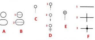
Relay contacts.
Depending on the design features, the intermediate relay contacts are normally open
(closing),
normally closed
(breaking) or
changeover
.
3.1. Normally open contacts.
As long as the supply voltage is not applied to the relay coil, its normally open contacts are always open
.
When voltage is applied, the relay is activated and its contacts close
, completing the electrical circuit. The pictures below show the operation of a normally open contact.
3.2. Normally closed contacts.
Normally closed contacts work the other way around: as long as the relay is de-energized, they are always closed
.
When voltage is applied, the relay is activated and its contacts open
, breaking the electrical circuit. The pictures show the operation of a normally open contact.
3.3. Changeover contacts.
For changeover contacts with a de-energized coil, the average
the contact attached to the anchor is
common
and closed with one of the fixed contacts. When the relay is triggered, the middle contact, together with the armature, moves towards the other fixed contact and closes with it, while simultaneously breaking the connection with the first fixed contact. The pictures below show the operation of a changeover contact.
Many relays have not one, but several contact groups, which makes it possible to control several electrical circuits simultaneously.
There are special requirements for intermediate relay contacts. They must have low contact resistance, high wear resistance, low tendency to weld, high electrical conductivity and long service life.
During operation, the contacts with their current-carrying surfaces are pressed against each other with a certain force created by the return spring. The current-carrying surface of a contact in contact with the current-carrying surface of another contact is called the contact surface
, and the place where the current passes from one contact surface to another is called
electrical contact
.
The contact of two surfaces does not occur over the entire apparent area, but only in separate areas, since even with the most careful treatment of the contact surface, microscopic tubercles and roughness will still remain on it. Therefore, the total contact area
will depend on the material, the quality of the contact surfaces and the compression force. The figure shows the contact surfaces of the upper and lower contacts in a greatly enlarged view.
At the point where current passes from one contact to another, electrical resistance occurs, which is called contact resistance
. The magnitude of the contact resistance is significantly influenced by the magnitude of the contact pressure, as well as the resistance of the oxide and sulfide films covering the contacts, since they are poor conductors.
During long-term operation, the contact surfaces wear out and can become covered with soot deposits, oxide films, dust, and non-conducting particles. Contact wear can also be caused by mechanical, chemical and electrical factors.
Mechanical wear occurs when contact surfaces slide and impact. However, the main cause of contact destruction is electrical discharges
, arising when opening and closing circuits, especially DC circuits with an inductive load. At the moment of opening and closing, the phenomena of melting, evaporation and softening of the contact material, as well as the transfer of metal from one contact to another, occur on the contact surfaces.
Silver, alloys of hard and refractory metals (tungsten, rhenium, molybdenum) and metal-ceramic compositions are used as materials for relay contacts. The most widely used material is silver, which has low contact resistance, high electrical conductivity, good technological properties and relatively low cost.
It should be remembered that there are no absolutely reliable contacts, therefore, to increase their reliability, parallel and serial connection of contacts is used: when connected in series, the contacts can break a large current, and parallel connection increases the reliability of the electrical circuit.
Designations depending on relay types
Depending on the type, relay devices may be designated differently on the diagrams.
Thermal Relay Models
Thermal protection relays are used to ensure normal operation of consumers. The devices turn off the electric motor instantly or after some time, preventing damage to the insulating surface or individual components.
In the diagrams, the thermal relay is designated as KSG and is connected to a normally closed contact. The connection is made using the TR system - to the output of the low-voltage electric motor starter.
Time relay
Designation of a time relay
The time relay is designated as KT and works on the principle of pausing under a certain influence. The device may also have cyclic activity.
To designate contacts operating for closure in accordance with GOST 2.755-87, the following are used:
- arc down – delay after voltage is applied;
- arc down – contact triggered upon return;
- two arcs in the opposite direction - a delay in applying and removing control voltage.
Pulse normally open contacts are designated as follows:
- a dash at the bottom with a diagonal angular line and an arrow without a lower part - pulse closure when triggered;
- a dash at the bottom with a diagonal corner line and an arrow without an upper part - pulse closure during return;
- a dash at the bottom with a diagonal angular line and a normal arrow - a pulse closure at the moment of operation and return.
The supply voltage supplied to the time relay is marked in the diagrams as a blue graph. The direction of voltage to the devices is indicated as a gray graph. The response delay range is indicated by red arrows. The time interval is represented by the letter T.
Current relay
Current relay on the diagram
The current relay controls current and voltage. An increase in the first parameter indicates a problem with the equipment or line.
On the diagrams, the device is marked as KA (the first letter is common for relays, starters, contactors, the second is specific for the current model). If BNT is present, it will be designated KAT, braking – KAW, filtration – KAZ. The coil in the drawings is depicted as a rectangle, the size of which is 12x6 mm. Contacts are designated normally open or normally closed.
The voltage winding is marked as a rectangle divided into two parts horizontally. The smaller one indicates the letter U; from the larger one, straight lines are directed horizontally up and down.
The current winding is indicated as a rectangle divided into two sectors in the horizontal direction. In the larger one, there are two lines horizontally at the top and bottom. On the smaller one, the letter I is written with a greater symbol (maximum current).
Features of the designation of electromagnetic relays on diagrams
Structurally, an electromagnetic relay is an electromagnet with one or more contact groups. Their symbols form the UGO of the device. The electromagnet winding is drawn as a rectangle with lead lines on both sides. Contact markers K are located opposite the narrow side of the winding and are connected by a dotted line (mechanical connection).
The contact pin can be depicted on one side, and the contacts - near the switching UGO. The assignment of contacts to a specific relay is indicated in the form of serial numbering (K 1.1., K 1.2).
Parameters or design features can be indicated inside the rectangle. For example, in the symbol K 4 there are two oblique dashes, i.e. The relay has two windings.
To distinguish them from standard devices, modifications with magnetically controlled contacts in a sealed housing are indicated by a circle. This is the reed switch symbol. The belonging of an element to a specific device is written in the form of contact letters (K) and serial numbers (5.1, 5.2).
Intermediate relay
Intermediate relay in the diagram
Intermediate relay devices are used to switch electrical circuits. They amplify the electrical signal, distribute electricity, and interface radio elements. The symbol of the coil is a rectangle with the letter K and a serial number in the drawing.
The designation of the intermediate relay contacts in the diagram is done using a letter, but with two numbers, which are separated by a dot. The first indicates the serial number of the relay device, the second indicates the number of the group of contacts of this device. The contacts located near the coil are connected by hatching.
The marking of the electrical circuit and terminals is carried out by the manufacturer. It is applied to the lid covering the working parts. The contact parameters are written under the diagram - the maximum switching current. Some brands number the pins on the sides of the connection.
The diagrams show the contacts in a state without voltage supply.
Main types of relays and their purpose
Manufacturers configure modern switching devices in such a way that operation occurs only under certain conditions, for example, when the current flowing to the input terminals of the control unit increases. Below we will briefly look at the main types of solenoids and their purpose.
Electromagnetic relays
An electromagnetic relay is an electromechanical switching device, the operating principle of which is based on the effect of a magnetic field created by a current in a static winding on the armature. This type of control unit is divided into electromagnetic (neutral) devices, which respond only to the value of the current supplied to the winding, and polarized ones, the operation of which depends on both the current value and polarity.
Operating principle of an electromagnetic solenoid
Electromagnetic relays used in industrial equipment are in an intermediate position between high-current devices (magnetic starters, contactors, etc.) and low-current equipment. Most often this type of relay is used in control circuits.
AC Relay
This type of relay, as the name suggests, operates when an alternating current of a certain frequency is applied to the winding. This switching device for alternating current with or without phase zero crossing control is a block of thyristors, rectifier diodes and control circuits. AC relays can be made in the form of modules based on transformer or optical isolation. These KU are used in AC networks with a maximum voltage of 1.6 kV and an average load current of up to 320 A.
Intermediate relay 220 V
Sometimes the operation of the electrical network and devices is not possible without the use of a 220 V intermediate relay. Typically, a control unit of this type is used if it is necessary to open or open multidirectional contacts of a circuit. For example, if a lighting device with a motion sensor is used, then one conductor is connected to the sensor, and the other supplies electricity to the lamp.
AC relays are widely used in industrial equipment and home appliances
It works this way:
- supplying current to the first switching device;
- from the contacts of the first KU, the current flows to the next relay, which has higher characteristics than the previous one and is capable of withstanding currents with high values.
Every year relays become more efficient and compact
The functions of the small size 220V AC relay are very diverse and are widely used as an auxiliary device in a variety of fields. This type of control unit is used in cases where the main relay cannot cope with its task or when there are a large number of controlled networks that are no longer able to service the head unit.
The intermediate switching device is used in industrial and medical equipment, transportation, refrigeration equipment, televisions and other household appliances.
DC relay
DC relays are divided into neutral and polarized. The difference between them is that polarized DC ICs are sensitive to the polarity of the applied voltage. The armature of the switching device changes direction of movement depending on the power poles. Neutral DC electromagnetic relays are independent of voltage polarity.
Electromagnetic DC control units are mainly used when there is no possibility of connecting to an AC electrical network.
Four-pin automotive relay
The disadvantages of DC solenoids include the need to use a power supply and higher cost compared to AC control units.
This video demonstrates the connection diagram and explains the operating principle of a 4-pin relay:
Watch this video on YouTube
Electronic relay
Electronic control relay in the device circuit
Having understood what a current relay is, let’s consider the electronic type of this device. The design and principle of operation of electronic relays are practically the same as in electromechanical control units. However, to perform the necessary functions, an electronic device uses a semiconductor diode. In modern vehicles, most relay and switch functions are performed by electronic relay control units and at the moment it is impossible to completely abandon them. For example, a block of electronic relays allows you to control energy consumption, the voltage at the battery terminals, control the lighting system, etc.
Two-character letter designations
For more accurate decoding and designation of elements on electrical circuits, two-letter, and in some cases multi-letter designations are used. Marking is carried out not only with the symbol of the general code of the element, but also with additional letters that more fully reveal the characteristics of each element. In order to organize such symbolism, a table has also been created in accordance with GOST 2.710-81:
| The first letter character required to be reflected in the marking | Group of main types of elements and devices | Elements that make up the group (the most typical examples) | Two letter code symbols |
| A | General purpose devices | – | |
| B | Various types of analogue or multi-charge converters, indicating or measuring sensors, devices that convert non-electrical quantities into electrical ones, with the exception of generators and power supplies | Loudspeakers | B.A. |
| Magnetostrictive elements | BB | ||
| Detectors of ionizing elements | BD | ||
| Receivers - selsyns | BE | ||
| Capsules - telephones | B.F. | ||
| Sensors - selsyns | B.C. | ||
| Thermal sensors | B.K. | ||
| Photocells | B.L. | ||
| Microphones | B.M. | ||
| Pressure Sensors | B.P. | ||
| Piezoelements | BQ | ||
| Speed sensors - tachogenerators | BR | ||
| Pickups | B.S. | ||
| Speed sensors | B.V. | ||
| C | Capacitors | – | |
| D | Integrated circuits, microassemblies | Analog integrated circuits | D.A. |
| Integrated circuits, digital, logical elements | DD | ||
| Storage devices | D.S. | ||
| Delay devices | D.T. | ||
| E | Miscellaneous elements | Heating elements | E.K. |
| Lighting lamps | EL | ||
| Squibs | ET | ||
| F | Protective devices, fuses, arresters | Discrete instantaneous current protection elements | F.A. |
| Discrete elements of inertial current protection | FP | ||
| Fuses | F.U. | ||
| Discrete voltage protection elements, arresters | F.V. | ||
| G | Generators and other power sources | Batteries | G.B. |
| H | Indicator and signal elements | Sound alarm devices | H.A. |
| Symbolic indicators | HG | ||
| Light signaling devices | H.L. | ||
| K | Contactors, starters, relays | Current relays | K.A. |
| Indicator relays | KH | ||
| Electrothermal relays | KK | ||
| Contactors, magnetic starters | K.M. | ||
| Time relay | KT | ||
| Voltage relay | KV | ||
| L | Chokes, inductors | Chokes for fluorescent lamps | LL |
| M | Engines | – | |
| P | Measuring instruments and equipment (use of PE marking is prohibited) | Ammeters | PA |
| Pulse counters | PC | ||
| Frequency meters | PF | ||
| Active energy meters | P.I. | ||
| Reactive energy meters | PK | ||
| Ohmmeters | PR | ||
| Recording devices | PS | ||
| Action time meters, clocks | P.T. | ||
| Voltmeters | PV | ||
| Wattmeters | PW | ||
| Q | Switches and disconnectors in power circuits | Circuit breakers | QF |
| Short circuits | QK | ||
| Disconnectors | QS | ||
| R | Resistors | Thermistors | RK |
| Potentiometers | R.P. | ||
| Measuring shunts | R.S. | ||
| Varistors | RU | ||
| S | Switching devices in measurement, control and signaling circuits | Switches and Switches | S.A. |
| Push-button switches | S.B. | ||
| Automatic switches | SF | ||
| Switches triggered by various factors: – from the level | SL | ||
| – from pressure | SP | ||
| – from position (travel) | S.Q. | ||
| – on rotational speed | S.R. | ||
| – on temperature | S.K. | ||
| T | Transformers, autotransformers | Current transformers | T.A. |
| Electromagnetic stabilizers | T.S. | ||
| Voltage transformers | TV | ||
| U | Communication devices, converters of non-electrical quantities into electrical ones | Modulators | UB |
| Demodulators | UR | ||
| Discriminators | UI | ||
| Rectifiers, frequency generators, inverters, frequency converters | UZ | ||
| V | Semiconductor and electrovacuum devices | Diodes, zener diodes | V.D. |
| Electrovacuum devices | VL | ||
| Transistors | VT | ||
| Thyristors | VS | ||
| W | Antennas, lines and microwave elements | Couplers | WE |
| Short circuits | W.K. | ||
| Valves | W.S. | ||
| Transformers, phase shifters | W.T. | ||
| Attenuators | W.U. | ||
| Antennas | W.A. | ||
| X | Contact connections | Sliding contacts, current collectors | XA |
| Pins | XP | ||
| Nests | XS | ||
| Separable connections | XT | ||
| High Frequency Connectors | XW | ||
| Y | Mechanical devices with electromagnetic drive | Electromagnets | YA |
| Brakes with electromagnetic drives | YB | ||
| Clutches with electromagnetic drives | YC | ||
| Electromagnetic cartridges or plates | YH | ||
| Z | Limiters, terminal devices, filters | Limiters | ZL |
| Quartz filters | ZQ |
In addition, GOST 2.710-81 defines special symbols to designate each element.
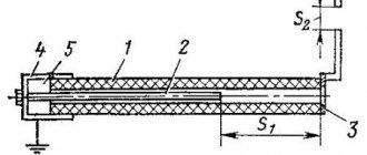
Relay device
The relay is a coil
, the winding of which contains a large number of turns of insulated copper wire.
Inside the coil is a metal rod ( core
) mounted on an L-shaped plate called
a yoke
.
The coil and core form an electromagnet
, and the core, yoke and armature form
the relay's magnetic circuit
.
An anchor is located above the core and coil
, made in the form of a metal plate and held by
a return spring
.
Movable contacts
are rigidly fixed to the armature , opposite which are located corresponding pairs
of fixed contacts
. Relay contacts are designed to close and open an electrical circuit.
Symbols on electrical diagrams. General information
Single-pole six-position switch with a moving contact that does not open the circuit when moving from the third to the fourth position 7. Most of the symbols in the electrical circuits of this element base are shown in the figures below.
The normally open contact is open; when it is switched to operating state, the circuit is closed.
If the electrical network or device is simple, everything can be placed on one sheet. This will be the complete schematic diagram.
It is advisable to indicate non-main signals for this part with links. Symbols of contactor coils and relays of different types: pulse, photo relay, time relay In this case, it is easier to remember, since there are quite serious differences in the appearance of the additional icons.
Some connections are buses - more powerful conductor elements from which taps can extend. Products for rooms with normal operating conditions IP from 20 to 23 have an unpainted middle; for wet rooms with increased protection housing IP44 and higher, the middle is tinted dark. The designations of these conventional elements can be used in electrical panel diagrams. Table 1.
Types and types of electrical circuits
Having dealt with the electrical circuits, we can move on to the designations of the elements indicated on them. A two-pole, six-position switch, in which the third contact of the upper pole operates earlier, and the fifth contact later, than the corresponding contacts of the lower pole 9. Radio engineering elements on electronic circuits are designated as follows.
Each diagram shows the connections between individual elements and conductors. UGO transformers Designation of current transformers on full and single-line in the diagram Graphic designation of electrical machines EM Electric motors, depending on the type, are capable of not only consuming energy. In order to graphically designate one or another electrical radio element, standard geometric symbolism is used, where each product is depicted separately or in combination with others. There are separate designations for two-key and three-key switches. How to draw a one-line diagram of a shield.
Designation sizes
A selection of materials from GOST related to the size of images of conventional graphic symbols of electrical circuit elements.
All images are inserted from GOST without changes.
GOST 2.701-84 Types and types of diagrams. General requirements for implementation (fragment)
2.4.2. Conventional graphic symbols of elements are depicted in the sizes established in the standards for conventional graphic symbols. Conventional graphic symbols, the size ratios of which are given in the relevant standards on a modular grid, must be depicted on diagrams in dimensions determined vertically and horizontally by the number of steps of the modular grid M (Fig. 2a). In this case, the step of the modular grid for each circuit can be any, but the same for all elements and devices of this circuit.
Crap. 2a
Conventional graphic symbols of elements whose dimensions are not established in the specified standards must be depicted on the diagram in the dimensions in which they are made in the relevant standards for conventional graphic symbols.
The dimensions of the conventional graphic symbols, as well as the thickness of their lines, must be the same on all diagrams for a given product (installation).
Notes:
1. All sizes of graphic symbols can be changed proportionally.
2. Conventional graphic symbols of elements used as components of the symbols of other elements (devices) may be depicted smaller in comparison with other elements (for example, a resistor in a rhombic antenna, valves in a dividing panel).
GOST 2.722-68 Electrical machines (fragment)
9. Dimensions of the main elements of conventional graphic symbols, table. 3.
GOST 2.721-74 Designations for general use. Table 7
GOST 2.728-74 Resistors, capacitors (fragment)
7. The dimensions of the conventional graphic symbols are given in table. 6. All geometric elements of conventional graphic symbols should be made with lines of the same thickness as the electrical communication lines.
Table 6
GOST 2.730-73 Semiconductor devices (fragment)
APPENDIX 2 Reference Dimensions (in a modular grid) of the main graphic symbols
GOST 2.732-68 LIGHT SOURCES (fragment)
4. Dimensions of the conventional graphic designation of an incandescent lamp
GOST 2.747-68 Dimensions of graphic symbols (fragment)
2. The dimensions of the graphic symbols are given in the table.
GOST 2.755-87 SWITCHING AND CONTACT CONNECTIONS DEVICES (fragment)
The dimensions (in the modular grid) of the main graphic symbols are given in Table 10. Table 10
GOST 2.756-76 RECEIVING PART OF ELECTROMECHANICAL DEVICES (fragment)
table 2
GOST 2.767-89 PROTECTION RELAY (fragment)
Dimensions (in a modular grid) of the main graphic symbols Table 4
GOST 2.768?90 ELECTROCHEMICAL, ELECTROTHERMAL AND THERMAL SOURCES (fragment)
RATIO OF THE SIZES OF THE MAIN GRAPHIC SYMBOLS
Additionally, I recommend reading the article: Dimensions of symbols in electrical circuits.
elektroshema.ru
Types of electrical circuits
The first thing to consider is that a diagram is a graphical representation of structural elements, nodes and their connections on paper, or in electronic form using generally accepted symbols. In total, there are about a dozen types of schemes, but the most common are the following:
- Functional;
- Principled;
- Assembly room.
They can be found in documentation for complex electronic devices, in equipment repair manuals for amateur craftsmen, or in wiring plans. Due to their prevalence, each species should be considered separately.
Functional diagram
It does not display the design in detail, but contains an image of the main blocks of the device with captions and functional units. Focusing on this drawing, you can only find out how the entire system of the device works, how the various elements are interconnected. It is advisable to use a functional diagram to describe, for example, a complex electronic device, but not always for power supply devices.
Schematic diagram
Contains a specific set of element designations, in accordance with the composition of the device. To correctly decipher the drawing, you need to know the basic conventional graphic displays of electrical elements. In this type of diagram, connections between devices and their constituent elements themselves are indicated. To display power lines, it is advisable to draw a linear diagram, and to indicate the types of electrical circuits and control and control partitions, a complete schematic diagram.
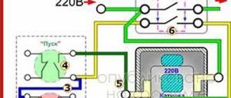
Connection diagrams
After the intermediate relay has been installed in the electrical cabinet, it should be connected to the electrical circuit. For this purpose, the contacts of the coil itself and direct contact elements are used. The relay usually has several pairs of NO normally open and NC normally closed contacts. The normal position is considered to be the absence of a signal to the coil. Since the coil does not have polarity, the contacts are connected arbitrarily.
Such a device is installed in control and automation circuits. Located between the actuator (for example, a contactor) and the reference source. The figure shows the electrical diagram of the device:
The picture shows an intermediate relay without voltage supply. If you apply it, the contacts will switch. The voltage in the coil can be different: 220, 24 and 12 volts.
How to connect the device is shown in the figure below:
In some cases, an intermediate type relay is used as a contactor, then the installation diagram will look like this:
As you can see, the intermediate relay has three groups of contacts that control the load and one group to hold the current in the coil. You can install an additional contactor, then the device is connected first to the contactor.
This device can also be connected to a motion sensor. Thanks to it, it is possible to connect several powerful lamps to the motion sensor system. Installation occurs as follows: the winding of the device is connected to the sensor, and the power contact switches the load in the lighting system. How to install such a sensor is shown below:
Another option for installing an electronic starter is to a thermostat. The diagram is shown in the picture (click to enlarge):
In this case, the thermostat and starter are connected in sequential order to the first phase and neutral wire (in the diagram they are designated as T1 and K1, respectively). The installation of the remaining contacts of the starter is carried out evenly between other phases.
Finally, we recommend watching a useful video on the topic:
https://youtube.com/watch?v=d6BA3PFlwCU
That's all I wanted to tell you about how to properly connect this device. We hope that the video instructions and intermediate relay connection diagrams provided were useful to you!
Relay according to the method of switching on the sensing element
According to the method of switching on the sensing element, primary, secondary and intermediate relays are distinguished.
The receiving element of electromagnetic relays is an electromagnet that converts the control current (voltage) into movement of the armature relative to the yoke.
The sensing elements of other electrical relays can be a magnetoelectric mechanism, an induction system, an electrodynamic mechanism, etc.
The sensing element of the primary relay is connected directly to the controlled circuits. In secondary relays, the sensing element is included in the controlled circuits through measuring transformers. Intermediate relays operate in circuits of actuating elements of other relays and are intended to amplify and convert signals from primary or secondary relays.
Operating principle of the contactor
The operating algorithm of this type of relay involves the use of electrodynamic forces created in a ferromagnet during the passage of electricity through the spiral of turns of the insulated wire of the coil.
Based on the technical features of the switch and the number of contact connections placed in it, the anchor either closes or opens them
The initial location of the L-shaped plate (anchor) is fixed by a spring. By supplying current to the magnet, the armature, with the commutating contact located on it, overcomes the spring forces and is drawn towards the magnetized field.
When moving, the shank located on the contact plane catches the lower contact circuit, moving it down. If the supply of electricity to the coil stops, the spring pulls the yoke back and the device returns to its original form.
Let's look at an example of how an electromagnetic-type relay works in a car.
If it is connected to a three-phase asynchronous motor, the following actions will be reproduced:
- Start – activation of the alarm.
- Starter activation.
- The closing of the last pair of contacts results in the start of the engine mechanism.
In addition, it is the relay that is responsible for turning off the engine when the reverse breaks. This eliminates the problem of sudden engine stops.
To recognize the type of electromagnetic contactor in production, marking values are used, consisting of a set of letters and numbers printed on the device
It is also important to know that an electromagnetic relay can be equipped with several groups of control contacts. The number of the latter depends entirely on the purpose of the specific model of the device.
Purpose and scope of intermediate relays
It is difficult to list the industries in which intermediate relays are used. In all industries, devices for household use, especially in elements of systems with electronic and electrical equipment, an intermediate relay can be installed.
There are several cases where auxiliary relays are used in complex electrical systems:
- For switching sections in various networks independent from each other;
- To increase the response delay of protective elements in circuits with high load currents;
- In secondary circuits, to control the parameters and operating modes of individual elements in high voltage circuits;
One relay on a production line can perform several switching operations simultaneously or sequentially in power or control circuits. In heating and water supply systems, when the deep-well pump is turned on, power is supplied to the relay coil, and when the group of contacts is closed, the control system for the operation of the pump is turned on. The operator’s display displays the main parameters: the presence of voltage on the pump, load currents in each phase, temperature and others, depending on the complexity of the circuit, as necessary.
The other pair will simultaneously close the power supply contacts to the coil of the magnetic starter, when triggered, the current will flow to all three phases of the pump motor. If the starter is assembled using a reversible circuit, another group simultaneously turns off the reversible circuit, eliminating a short circuit.
In a heating system, a signal with weak currents is not capable of turning on the coils of powerful magnetic starters or relays. Therefore, the intermediate relay acts as an amplifier of the control signal; the signal from the heat sensor turns on the intermediate relay, the contacts of which supply voltage to the windings of the magnetic starter, the contacts of which close and power is supplied to heating elements, boilers or other powerful heating devices.
How does an electromagnetic relay work?
An electromagnetic relay is an electromechanical system consisting, in the simplest case, of a coil of wire (winding) placed on a metal core and a moving part (armature) connected to springy contact plates. Its operation is based on the principle of electromagnetic induction.
When voltage is applied to the winding, current flows through it, electromagnetic induction occurs, magnetizing the core made of soft magnetic material.
Soft magnetic material is a special iron-based alloy that is quickly magnetized and quickly loses magnetization when the electromagnetic field disappears.
At a certain amount of current in the winding, the attractive force of the core exceeds the elastic force of the armature spring - and the armature is attracted to the core.
The armature is connected to mechanical elements with flexible contacts, which, when the armature is attracted to the core, are closed or opened, depending on the specific design.
One relay can have several groups of contacts.
To reduce the transition resistance, the working parts of the contacts are coated with noble metals (gold, palladium) or alloys based on silver, cadmium and other metals. The type of contact coating affects the cost of the relay as a whole.
To protect the winding and contacts from external influences, the entire structure is often placed in a closed housing. Markings are applied to the body.
Relay protection marking
To indicate relay protection, markers of machines, instruments, devices and the relay itself are used in the drawings. All devices are depicted in conditions without voltage in all power lines. According to the type of purpose of the relay device, three types of circuits are used.
Schematic diagrams
The schematic drawing is carried out along separate lines - operating current, current, voltage, alarm. The relays on it are drawn in dissected form - the windings are on one part of the picture, and the contacts are on the other. There are no markings of internal connections, clamps, or operating current sources on the circuit diagram.
Wiring diagram
Marking of protection devices is carried out on working diagrams intended for the assembly of panels, control or automation. All devices, clamps, connections or cables reflect the connection details.
The wiring diagram is also called the executive diagram.
Structural diagrams
Allows you to highlight the general structure of relay protection. The nodes and types of mutual connections will be indicated. To mark organs and nodes, rectangles with inscriptions or special indices are used to explain the purpose of using a particular element. The structural diagram is also supplemented with symbols of logical connections.
Symbols on power supply diagrams
The diagrams even show the shape and dimensions of the lamps.
The diagrams even show the shape and dimensions of the lamps. In functional drawings, contactors are depicted taking these features into account.
In addition, in the conventional graphic symbols on electrical circuit diagrams, special symbols are additionally used to explain the operating features of a particular circuit element. Letters and numbers are used to symbolically designate individual elements, their denominations and distances between objects.
In rooms with normal operating conditions, switches with IP20 are installed, maybe up to IP. The simplest example is an ordinary switch. Some can even immediately indicate possible problems that may arise during operation. If the symbols on various electrical circuits of GOST contain elements that do not have information about sizes, then these components are made in sizes corresponding to the standard image of the UGO of the entire circuit.
Types of electrical circuits
Almost, because the standards have not been updated for a long time and some elements are drawn by everyone as best they can. If the symbols on various electrical circuits of GOST contain elements that do not have information about sizes, then these components are made in sizes corresponding to the standard image of the UGO of the entire circuit. The normally off position of the switch corresponds to a shaded rectangle, and an unshaded rectangle corresponds to the switch being on. Gives a general idea of the functioning of the object.
Each of the designations can be used in certain cases. Control circuits are operational circuits - these are buttons, fuses, coils of starters or contactors, contacts of intermediate and other relays, contacts of starters and contactors, voltage phase control relays, as well as connections between these and other elements.
See also
The basis of any electrical circuit is represented by conventional graphic symbols of various elements and devices, as well as the connections between them. D - Display of battery or galvanic power source. Recent standardization was approved eight years ago by GOST. The option on the right is for open mounting.
Quartz filter ZQ Sequential numbers of elements should be assigned, starting from one, within a group of elements that are assigned the same letter position designation in the diagram, for example, Q1, Q2, Q3, in accordance with the sequence of their location in the diagram from top to bottom and from left to right. Given such circumstances, designers adopt practical experience from more experienced colleagues; they simply know how to do many things correctly, but do not know why. The values of the required parts are sometimes indicated next to the image, but in large multi-element circuits they are written in a separate table. On radio installation diagrams, the position of radio components, methods and order of their installation are noted. How wires, cables are designated, the number of cores and methods of laying them On wiring diagrams it is often necessary to indicate not only how the cable or wire runs, but also its characteristics or method of installation. How to read a valve circuit diagram
UGO dimensions
Dimensions of graphic symbols in electrical diagrams
| Name | Designation | Name | Designation |
| Switching device contact. General designation: closing | Switching device contact. General designation: switching | ||
| Heating element | Contact without self-resetting: normally open | ||
| Push-button switch | Normal contact with retarder, active: when activated | ||
| Plug connection contact: pin | Plug connection contact: socket | ||
| Removable connection contact | Electric machine rotor | ||
| Sensing part of electrothermal relay | Electromechanical device coil | ||
| Incandescent lamp (lighting and signal) | Electric bell | ||
| The fuse is fusible. General designation | Resistor is constant | ||
| Galvanic or battery cell | Grounding | ||
| Fixed capacitor | Electrolytic capacitor |
GOST 2.721-74
| Name | Designation | Name | Designation |
| Drive using bimetal | Float drive | ||
| Drive driven by pressing a button | Diaphragm drive |
GOST 2.755-87
The dimensions of the graphic symbols are given in the modular grid.
| Name | Designation | Name | Designation |
| Switching device contact 1) normally open | Switching device contact 2) normally open | ||
| Switching device contact 3) changeover | Pulse closing contact during operation and return |
| Name | Designation | Name | Designation |
| Three-pole switch | Electric machine stator | ||
| Inductor, winding | Electro-mechanical device coil: with one additional graphic field | ||
| Electrical measuring device: integrating (for example, an electric energy meter) | Electrothermal device without heating chamber; electric heater |
GOST 2.730-73 (amended 1989)
Dimensions (in modular grid) of symbols
| Name | Designation | Name | Designation |
| Diode | Thyristor diode | ||
| Transistor | Field effect transistor |
studfile.net
Application of alarm relay
Indicating relays are used in electrical networks with constant and variable current characteristics. Switching is used in automation systems, regulation by electric drives. The indicating relay is used in electrical power and technological units and control systems over them.
Instrument indicating relay
Indicating relays are used in most industries. The most popular area of application is energy. In this case, switching occurs through automation, with the help of protection, and also by workers.
Some types of relays are found in household appliances, such as refrigerators, washing machines, televisions, and heating boilers. These devices are more sensitive to voltage changes and react to both low and high voltage levels. In this case, such household appliances may fail.
In addition, the devices are in great demand in the military, aircraft construction, spacecraft, vehicles and railways. Relays for these areas of production are manufactured taking into account shocks, large vibrations, linear acceleration, that is, the destructive factors of long-term and severe use. At the same time, the permissible position is indicated at which the relay remains operational.