Welding arc. Characteristics of the welding arc
A welding arc is a powerful, long-lasting electrical discharge between energized electrodes in a mixture of gases and vapors.
The arc is characterized by high temperature and high current density. The welding arc as an energy consumer and arc power source (welding transformer, generator or rectifier) forms a mutually interconnected energy system. There are two modes of operation of this system: 1) static, when the voltage and current values in the system do not change for a sufficiently long time; 2) transient (dynamic), when the voltage and current values in the system continuously change. However, in all cases, the burning mode of the welding arc is determined by the current (ID), voltage (UD), the size of the gap between the electrodes (the so-called arc gap) and the connection between them.
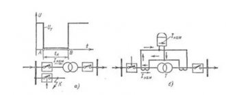
In the arc gap ID (Fig. 1, a) three regions are distinguished: anode 1, cathode 2 and arc column 3. The voltage drop in the anode and cathode regions is constant for given welding conditions. The voltage drop per unit length of the arc column is also a constant value. Therefore, the dependence of the arc voltage on its length is linear (Fig. 1, b).
The stability of the welding arc is determined by the relationship between current and voltage. A graphical representation of this dependence (Fig. 2) at a constant arc length is called the static current-voltage characteristic of the arc. The graph clearly shows three main sections: an increase in current in section I is accompanied by a decrease in arc voltage; in section II, the arc voltage changes little; in section III the tension increases. The combustion modes of the welding arc corresponding to the first section are unstable at the voltages of existing power sources. In practice, the welding arc will be stable in the second and third sections of the current-voltage characteristic. With an increase or decrease in arc length, the characteristics will shift to positions 2 and 3, respectively (see Fig. 2). For electrodes with a smaller diameter, the characteristics shift to the left, for larger diameters - to the right.
Rice. 1. Welding arc burning between non-consumable electrodes: a - arc diagram, b - dependence of arc voltage (Usp) on the arc gap (/d): 1 - anode region, 2 - cathode region, 3 - arc column
Fig. 2 Current-voltage characteristic of the arc (volt-ampere characteristic)
Shown in Fig. 2 volt-ampere characteristic of the arc was taken at a constant length of the welding arc. When welding with a consumable electrode, the length of the arc gap continuously changes. In these cases, you should use the characteristics that determine the relationship between voltage and arc current at a constant feed speed of the electrode wire (Fig. 3, curves 1 and 2). Each feed speed corresponds to a certain current range at which the welding arc burns stably and the electrode melts. In this case, with small changes in current, the voltage changes within large limits. This dependence is usually called the characteristic of stable operation. It, like the current-voltage characteristic, depends on the length of the electrode extension and the feed speed.
These patterns are valid for direct and alternating current, since the type of current does not affect the shape of the current-voltage characteristics of the electric arc. The shape of the characteristic is influenced by the geometry and material of the electrodes, the cooling conditions of the arc column and the nature of the environment in which the discharge occurs.
The stability of the welding arc and welding mode depend on the conditions of existence of the arc discharge and the properties, parameters of the power sources and electrical circuit. The external characteristic of the power source (curve 3 in Fig. 3) is the dependence of the voltage at its terminals on the load current. The following external characteristics of power sources differ (Fig. 4): falling 1, gently falling 6, rigid 5, rising 3 and vertical 2. A power source with one or another external characteristic is selected depending on the welding method. The control device of each source gives a number of external characteristics (“family of characteristics”). The steady-state operating mode of the system: “welding arc - power source” is determined by the intersection point A of the external characteristic of the power source (1, 2, 3, 5 or 6) and the current-voltage characteristic 7 of the welding arc.
Fig. 3 Volt-ampere characteristic of the welding arc (volt-ampere characteristic) 1.2 at a constant wire feed speed (characteristic of stable operation) and external characteristics of power sources 3, 4 and 5
Fig.4 External characteristics of power sources 1, 2, 3, 5, 6 and current-voltage characteristics of the welding arc 4, 7
The welding process will be stable if the arc discharge exists continuously for a long time at given voltage and current values. As can be seen from Fig. 4, at points A and B of the intersection of the external characteristics of the arc 7 and the power source, there will be an equilibrium in current and voltage. If for any reason the current in the welding arc corresponding to point A decreases, its voltage will be less than the steady value of the power source voltage; this will lead to an increase in current, i.e., to a return to point A. On the contrary, with a random increase in current, the steady-state voltages of the power source turn out to be less than the arc voltage; this will lead to a decrease in current and, consequently, to the restoration of the welding arc combustion mode. From similar reasoning it is clear that at point B the welding arc burns unstable. Any random changes in the current develop until it reaches a value corresponding to the stable equilibrium point A or until the arc breaks. With a flattened external characteristic (curve 6), stable arcing will also occur at point A.
When working on a falling section of the current-voltage characteristic of the arc, the external characteristic of the source at the operating point should be steeper than the static characteristic of the welding arc. With increasing arc characteristics, the external characteristics of the source can be hard 5 or even increasing 3.
When manual welding, when changes in arc length are possible, it must have a sufficient margin of stability.
All other things being equal, the stability margin increases with increasing slope of the external characteristic of the power source. Therefore, for manual welding, sources with steeply falling characteristics are used: the welder can lengthen the arc without fear that it will break, or shorten it without fear of an excessive increase in current.
Self-regulation of the welding arc. In automatic or semi-automatic welding with a consumable electrode, its feed speed (va) is equal to the melting speed. If the arc gap is accidentally reduced (curve 4 in Fig. 4), the current increases and the wire will begin to melt faster. As a result, the arc gap will gradually increase and the welding arc will reach its original length. The same thing will happen if the arc is accidentally lengthened. This phenomenon is called self-regulation of the welding arc, since the restoration of the original mode occurs without the influence of any regulator. Self-regulation occurs the more actively, the better the external characteristic of the power source and the higher the electrode feed speed. Therefore, for mechanized consumable electrode welding, power sources with flat-sloping external characteristics should be selected. When welding with direct current in shielding gases, when the static characteristic of the welding arc takes on an increasing shape, it is rational to use sources with a rigid characteristic for self-regulation systems. However, their open-circuit voltage is low and may even be less than the operating voltage of the arc, which makes its initial initiation difficult. In these cases, it is desirable to use power sources in which the external characteristic in the working part is a rigid or gently increasing current-voltage characteristic, and the open-circuit voltage is slightly increased, as shown by the dotted line in Fig. 4.
The AC welding arc requires power sources to reliably restart the welding arc. This is achieved by the correct choice of relationships between the open circuit, ignition and arc voltages and the parameters of the welding circuit. The simplest way to obtain a stable welding arc is to include reactance in the welding circuit. Due to this, at the moment of re-excitation of the arc, the voltage on the arc can increase sharply (Fig. 5) to the value of the ignition voltage (U3). The dotted t/xx curve represents the power supply voltage at no-load. Under load, due to the presence of reactance, the welding current lags behind the voltage in time.
When the arc breaks, the voltage across the arc gap must rise to a value corresponding to the instantaneous value of the no-load voltage of the power source. Due to the current lagging behind the voltage, this voltage is sufficient to re-excite the welding arc (Un).
Metal transfer in a welding arc and requirements for the dynamic properties of power sources. The following types of transfer of electrode metal into the weld pool are distinguished: large-droplet, characteristic of low current densities; small-droplet, jet, when the metal flows from the electrode in very small drops. Drops of molten metal periodically close the arc gap, or if short circuits do not occur, they periodically change the length of the arc. At a high current density in the electrode, fine-droplet transfer of metal is observed, without noticeable fluctuations in the length and voltage of the welding arc.
Voltage, current and arc length undergo periodic changes from no-load to short circuit; in operating mode, an arc burns, a drop forms and grows. Subsequently, if there is a short circuit between the drop and the bath, the current increases sharply. This leads to compression of the drop and destruction of the bridge between the drop and the electrode. The voltage increases almost instantly and the welding arc is excited again, i.e. the process is repeated periodically. Mode changes occur within a fraction of a second. Therefore, the power source must have high dynamic properties, i.e., a high rate of increase in voltage when the circuit is broken and the required rate of increase in current.
Rice. 5 Oscillogram of current and arc voltage when welding with alternating current.
At a low rate of current rise, unmelted wire enters the bath. It heats up relatively slowly over a large area, which is then destroyed. If the current increases too quickly, the bridge between the bath and the drop of electrode metal quickly overheats and collapses with an explosion. Some of the molten metal splashes out and does not enter the seam.
To avoid spatter, it is necessary to increase the electromagnetic inertia of the power source by increasing the inductance of the welding circuit.
Extinguishing methods
It should be noted that arc extinction occurs for various reasons. For example, as a result of cooling of the column, a voltage drop, or when the air between the electrodes is displaced by external vapors that prevent ionization.
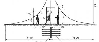
In order to prevent the formation of arcs on high-voltage power line wires, they are spaced over a long distance, which eliminates the possibility of breakdown. If a breakdown between the wires does occur, the long barrel will quickly cool and extinguishment will occur.
To cool the barrel, it is sometimes divided into several components. This principle is often used in the designs of air circuit breakers designed for voltages up to 1 kV.
Some circuit breaker models contain multiple arc chutes to promote rapid cooling.
Rapid ionization can be achieved by evaporating certain materials surrounding the space of the moving knives. High-pressure evaporation blows away the plasma of the barrel, resulting in extinguishing.
There are other methods: placing contacts in oil, auto-blowing, using electromagnetic damping, etc.
The nature of the phenomenon
The arc formation process is as follows:
- The welder touches the metal workpiece with the electrode for a split second.
- At the moment of contact, a short circuit occurs, accompanied by the flow of high current and, as a consequence, a powerful release of heat.
- The metal melts at the point of contact. It becomes viscous and viscous.
- At the moment the consumable is separated from the workpiece, a drop of melt trails behind it.
- Lengthening, it becomes thinner with the formation of the so-called. cervix. At some point, it evaporates and turns into a cloud of charged particles. At the same time, due to the high temperature in this zone, the air or shielding gas is ionized.
- Under the influence of an electric field, negative charge carriers rush to the anode, positive charge carriers - to the cathode. The process of current flow in the plasma begins.
At the moment of contact, a short circuit occurs and the metal at the point of contact melts. Each stage lasts milliseconds, the discharge occurs almost instantly. The current is then maintained by the emission of electrons at the cathode. On their way to the anode, they ionize gas and metal vapor, increasing the number of free charge carriers.
Modern welding machines are equipped with a high-frequency vibration generator (oscillator). This device allows you to excite the arc in a non-contact manner.