Why is labeling necessary?
Specific colors in electrics were not chosen by chance. Colored wiring is necessary for safe electrical work to avoid short circuits and electric shock. Previously, the color of conductors was black or white, which resulted in great inconvenience for electricians.
Previously, when disconnecting, it was necessary to supply power to the conductors, after which zero and phase were determined using control. Using coloring took all that pain away because everything became very clear.
Color coding is almost always applied along the entire length of the conductor. It helps to establish the assignment of each conductor to a specific group in order to facilitate their switching. There are three types of wires in electrics: phase, neutral and ground.
electrical safety
Alternating electric current with a voltage of 220 V or 380 V is dangerous for humans. Careless touching of exposed wires or metal parts of electrical equipment that may be live can result in severe burns or fatal injury. For this purpose, the PUE gives an answer to the questions: how the color of the wires phase and zero, L and N in electrics will help to clearly determine the security system used in a given electrical network.
Rules for marking live parts according to the PUE
To ensure clarity, simplicity and ease of recognition of individual parts of the electrical network, in accordance with clause 1.1.30 of the PUE, all electrical installations must have an alphanumeric and color designation. Moreover, the presence of one of these designations does not eliminate the need for the other.
Marking by color
Marking wires by color is the most visual and allows you to quickly determine the purpose of any wire. This marking can be done by selecting wires with the appropriate core insulation color, by applying paint to the busbars, or by painting or applying special colored tape at the core junctions.
Moreover, the paint on the tires may not be applied along the entire length, but only at the connection points or at the ends of the tires.
So:
- If we talk about the color designation of wires and cables, then we should start with the phase conductors. According to clause 1.1.30 of the PUE in a three-phase network, phase conductors must be marked in yellow, green and red. This is how phases A, B and C are designated respectively.
- The instructions for a single-phase electrical network suggest the designation of the phase wire in accordance with the color of which it is a continuation. That is, if a phase conductor is connected to phase “B” of a three-phase network, then it should be green.
Note! In a single-phase network in an apartment or house, you often do not know which phase your phase wire is connected to. In order to comply with GOST, you do not have to find out this at all. It is enough to designate the phase conductor with any of the proposed colors. After all, for a single-phase lighting network, it does not matter at all which phase your conductor is connected to. The only exception is the lighting network, which uses two different phase conductors.
- As for the neutral conductors, they should be blue in color. Moreover, the color of the neutral core does not depend on the three-phase, two-phase or single-phase network in front of you. It is always indicated in blue.
- Wire markings with a yellow-green stripe indicate a protective conductor. It is connected to the housing of electrical appliances and provides safety from electric shock if the insulation of electrical equipment is damaged.
- If the neutral and protective conductors are combined, then according to clause 1.1.29 of the PUE, such a wire core should have a blue color with yellow-green stripes at its ends. To make such markings with your own hands, you just need to take a blue wire and mark it with paint on its end seals or use colored electrical tape for this.
- As for DC networks, the positive core of a wire or bus should be indicated in red, and the negative core in blue. In this case, the designation of the neutral and protective conductors corresponds to the markings in alternating current networks.
Letter marking of wires
But color marking of wires is not always convenient. In switchboards, switchgears and on diagrams, the letter designation is much more convenient. It must be used in conjunction with the color designation.
So:
- The letter marking of phase wires in a three-phase network corresponds to their colloquial designation - phase “A”, “B” and “C”. For a single-phase network it should be the same, but this is not always convenient. Moreover, it is not always possible to reliably determine which phase exactly. Therefore, the designation “L” is often used. Clause 1.1.31 of the PUE standardizes not only the letter and color designation of conductors, but also their location. So for a three-phase network with vertical busbars, phase “A” should be the topmost, and phase “C” the bottom. And with a horizontal arrangement of conductors, the phase “C” closest to you should be, and the most distant phase “A”.
- If the wires are marked in the panel, then the symbol “N” indicates the neutral wire.
- The letter designation “PE” is used to designate the protective conductor. In addition, the grounding sign is often used, but the fact is that it cannot always accurately indicate the network diagram.
- The fact is that you may come across the designation “PEN”. It denotes the combination of the neutral and protective conductors. This is possible in TN-CS systems, which we discussed in one of our previous articles.
- But the marking of DC electrical wires is carried out with the symbolisms “+” and “¬―”. Which respectively means positive and negative wire. For direct current there is another difference. The zero core is designated by the symbol “M”, which is sometimes misleading.
How are zero working neutral conductors designated? answer
| Beginning of the form |
| Indicated by the letter N and green | Incorrect answer |
| Indicated by the letter N and white | Incorrect answer |
| Indicated by the letter N and blue color | Correct answer |
| Indicated by the letter N and the color yellow | Incorrect answer |
Which rooms are considered wet?
| Beginning of the form |
| Rooms in which the relative air humidity is more than 60%, but does not exceed 75% | Correct answer |
| Rooms in which the relative air humidity does not exceed 75% | Incorrect answer |
| Rooms in which the relative air humidity is more than 75%, but does not exceed 90% | Incorrect answer |
| Rooms where the relative humidity is close to 100% | Incorrect answer |
Within what period of time from the date of the last knowledge test can employees who received an unsatisfactory assessment be re-tested?
| Beginning of the form |
| No later than 1 week from the date of the last inspection | Incorrect answer |
| No later than 2 weeks from the date of the last inspection | Incorrect answer |
| No later than 3 weeks from the date of the last inspection | Incorrect answer |
| No later than 1 month from the date of the last inspection | Correct answer |
| No later than 3 months from the date of the last inspection | Incorrect answer |
For what period is an order issued for work on electrical installations?
| Beginning of the form |
| No more than 5 calendar days from the date of commencement of work | Incorrect answer |
| No more than 10 calendar days from the date of commencement of work | Incorrect answer |
| The order is of a one-time nature, its validity period is determined by the length of the executors’ working day | Correct answer |
| No more than 20 calendar days from the date of commencement of work | Incorrect answer |
| For the entire duration of the work | Incorrect answer |
In what case should electric motors be immediately disconnected from the mains?
| Beginning of the form |
| At the appearance of smoke or the first signs of fire | Incorrect answer |
| If the drive mechanism breaks down | Incorrect answer |
| When bearings heat up above the set temperature | Incorrect answer |
| In case of an accident involving personnel | Incorrect answer |
| In any of the above cases | Correct answer |
Didn't find what you were looking for? Use the search:
Best sayings:
Only sleep brings a student closer to the end of the lecture.
And someone else's snoring alienates him. 8843 — | 7556 - or read all.
91.146.8.87 © studopedia.ru Not the author of the materials posted. But it provides free use. Is there a copyright violation? Write to us | Feedback.
Disable adBlock! and refresh the page (F5)
very necessary
| Indicated by the letter N and green | Incorrect answer |
| Indicated by the letter N and white | Incorrect answer |
| Indicated by the letter N and blue color | Correct answer |
| Indicated by the letter N and the color yellow | Incorrect answer |
What maximum voltage value should be used to power portable (hand-held) lamps used in hazardous areas?
| Not higher than 12 V | Incorrect answer |
| Not higher than 42 V | Incorrect answer |
| Not higher than 50 V | Correct answer |
| Not higher than 127 V | Incorrect answer |
Which rooms are considered wet?
| Rooms in which the relative air humidity is more than 60%, but does not exceed 75% | Correct answer |
| Rooms in which the relative air humidity does not exceed 75% | Incorrect answer |
| Rooms in which the relative air humidity is more than 75%, but does not exceed 90% | Incorrect answer |
| Rooms where the relative humidity is close to 100% | Incorrect answer |
What groups are the electrical technical personnel of the organization divided into?
| For operational, administrative and repair | Incorrect answer |
| For administrative, technical and operational repair | Incorrect answer |
| For operational, administrative-technical, operational-repair and maintenance | Correct answer |
| For operational, operational-repair and repair | Incorrect answer |
Standard color coding of wires and busbars
Colored insulation of conductors today is an essential attribute for successful and correct installation of electrical wiring. This solution is by no means a way to make wires beautiful and attractive to the consumer; it is a convenient color marking, standardized and regulated throughout the civilized world, which is, without exaggeration, a necessity.
Color-coded wires provide precise identification of each conductor. The color of the core insulation determines its purpose in a group of several conductors and facilitates the switching and installation process.
This solution eliminates possible errors that could lead to fatal electric shock or short circuit. Electrical repairs and maintenance are also safer when wires are accurately marked.
The standard set out in the PUE strictly defines the colors of the markings, and thanks to this standard it becomes possible to easily identify each conductor, each cable core in a group by color or alphanumeric code.
As a rule, the entire conductor has a certain color, but it is also permissible to mark only the ends of individual cores at switching points where it is possible to use colored electrical tape or colored cambrics. Next, we will look in more detail at how exactly such marking is carried out for single-phase, three-phase and direct current networks.
For three-phase AC networks
In three-phase alternating current networks, high-voltage transformer inputs both at stations and substations, as well as busbars, are painted in the following colors, according to the phases:
- Phase “A” is colored yellow;
- Phase “B” is colored green;
- Phase “C” is colored red.
For DC networks
DC circuits are characterized by only two buses: positive and negative. Here the positive wire (positive charge bus) is marked in red, and the negative wire (negative charge bus) is marked in blue, because the neutral and phase wires are fundamentally absent here. The middle wire (M) is marked blue.
In the case where a dc network containing two conductors is created by branching from a three-wire dc circuit, the conductors are marked in the same way as the corresponding conductors of the original three-wire circuit.
Phase, neutral and ground in electrical wiring
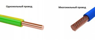
AC electrical networks are now always laid with multi-core wires insulated with cores of different colors, this greatly simplifies the installation process. If the wiring in the room is carried out by one installer, and in the future other people will carry out maintenance and repair of the network, they will no longer be forced to constantly identify “phase” and “zero”, they will simply be guided by color.
But in the old days this was a real problem, because the insulation was one color - either white or black. Now a standard has been developed, and in accordance with GOST R 50462 “Identification of conductors by colors or digital designations”, the cores are separate and in cables have strictly regulated designations.
The function of marking is to create the ability to quickly and easily visually determine the purpose of each specific conductor for any section of it; this is one of the main requirements of the PUE. What colors, according to GOST, should conductors have in AC electrical installations for voltages up to 1000 volts and with a solidly grounded neutral, which includes almost all residential buildings and administrative buildings?
The neutral working conductor (N) is marked in blue. For the neutral protective conductor (PE) - yellow-green markings in the form of stripes along or across the core. This marking in the named color combination is relevant only for grounding conductors (for neutral protective conductors).
When the neutral working conductor is made combined with the neutral protective conductor (PEN), then along the entire length of the wire the marking is blue, and at the connection points (at the ends of the conductor) there are yellow-green stripes, or vice versa: a yellow-green conductor with blue ends.
Thus, neutral wires are marked with the following colors:
- Neutral working wire (N) – blue marking;
- Neutral protective conductor (PE) – yellow-green marking;
- Neutral combined wire (PEN) - yellow-green marking with blue marks at the ends or vice versa.
Phase wires, in accordance with the PUE standard, can be marked in one of these colors: red, black, purple, brown, gray, pink, orange, turquoise, or white. If a single-phase electrical circuit is obtained by branching from a three-phase network, then the phase wire of the resulting single-phase circuit must necessarily match the color of the original wire of the three-phase network from which the branch was made.
The wires are marked so that the colors of the phase wires in no way match the color of the neutral conductor. And if an unmarked cable is used, then color marks are made at the ends of the cores, at the joints, using heat-shrink tubes or colored electrical tape. But to prevent unnecessary work on making tags, it is enough to initially choose the right insulation color, choosing a cable of sufficient length for your needs.
Sometimes an electrician at work has to deal with not very pleasant situations when the wiring has already been done, and neither the connections in the panel nor the wires are marked, in this case the person has to waste time and, using a probe, identify “phase”, “zero”, and "grounding".
However, you should always remember that even if it is not possible to purchase a wire of the desired color, you can, of course, use a wire of any color, but then you must definitely mark the ends of the wires with at least colored heat shrink or colored electrical tape. And always remember to be careful when installing electrical wiring and always follow safety precautions.
Purpose of conductors
The use of neutral conductors in an electrical panel
The neutral working conductor has another name - network conductor. The load current flows through it. In the diagram it is designated by the Latin letter “N”.
The main task of the neutral protective conductor is to ensure safety. In systems with a zero terminal of a solidly grounded transformer, it switches the conductive parts of electrical receivers and the zero point of the supply transformer. In emergency or emergency situations, they are under attack.
The following electrical elements are subject to protection from indirect contact (according to PUE 1.7.76):
- housings made of metal, portable and mobile devices;
System with PEN wire and two zeros - metal structures of transformers, electrical machines and lighting devices;
- metal cases of various designs with electrical equipment, cable couplings, trays and various distribution devices;
- steel casings of floor and apartment panels, distribution panels.
As protection, switching of these devices with a solidly grounded neutral in TN or TT, IT systems is used. The last two are grounded.
Schematically, the neutral protective conductor is designated “PE”. When the electrical circuit is operating normally, no current flows through the PE.
In the diagrams, the combination “PE” means the neutral protective conductor, as well as all protective segments of the circuit, for example, laid buses and conductors, grounding conductors, individual conductors in cables, as well as a wire in the potential equalization system.
Wiring inside the house
Wiring inside the house is carried out only with single-phase lines and copper wires. In electrical circuits used for domestic purposes, the working zero should always be blue! According to the PUE, intra-house lines must be laid with a grounding conductor. In all three-core conductors made in accordance with GOST, suitable for interior work, the grounding wire is yellow-green.
If the three-core conductor is flexible PVA type, then the phase conductor is usually brown. For indoor wiring, it is better to use wires made of cast copper. If the conductors are marked with stripes, then a conductor with a stripe of any color except blue and yellow-green is phase.
If the cable does not have a yellow-green conductor, use a conductor with a green stripe as the ground wire. The ground wire may be marked in pure yellow. In cables whose cores are entirely painted, the white wire is the phase wire.
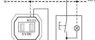
Connection to electric stove
A 220 V household electric stove is connected to a special outlet that can withstand high power. The colors of the conductors are red, green, blue, where red is the phase, green is the ground, blue is the neutral conductor.
There is a nuance: in foreign-made electric stoves and hobs designed for 220/380 V, the connection is made with a four-wire cable:
- blue – zero;
- yellow-green conductor – grounding;
- black conductor – phase A;
- brown conductor – phase B.
When connecting to a single phase network, it is allowed to combine the phase conductors on the electric stove under one contact clamp.
Neutral wire
The neutral conductor is the wire connected to the middle (null) point of the electrical system. In the standard connection diagram, this is a combined neutral working and neutral protective conductor in a three-phase circuit. The color of the neutral wire is all blue with yellow-green ends or all yellow-green with blue ends.
Wires are marked by color, letters and numbers. GOST until 2009 interpreted the possibilities of marking wires more broadly. Since 2009, the standards have been revised towards a more clear classification of colors and have eliminated notes that make it possible not to mark conductors.
The 2009 national standard clarified the terminology and expanded the alphanumeric classification. For electrical circuits until 2009, classic conductor colors were used: yellow, green, red.
In the classic version of three-phase circuits up to 1000 volts, conductors are marked in the following combinations:
- Phase A – L1, yellow – brown recommended.
- Black is recommended in phase B – L2, green.
- Phase C – L3, red – gray recommended.
- Neutral conductor – N blue.
- Combined working neutral with grounding conductor - PEN, blue with yellow-green tips - yellow-green with blue tips.
- Grounding conductor – PE, yellow-green.
This combination does not imply either the direction of rotation or phasing.
Rules for observing the colors of electrical wiring during installation
A three-core or two-core wire is laid from the distribution box to the switch, depending on what type of switch is installed: a single-key or two-key switch. The phase is broken, not the neutral conductor. If there is a white conductor available, it will be the power supply. The main thing is to maintain consistency and consistency in coloring with other electricians, so that it doesn’t turn out like in Krylov’s fable: “The Swan, the Crayfish and the Pike.”
On sockets, the protective conductor (yellow-green) is most often clamped in the middle part of the device. We maintain polarity, zero worker is on the left, phase is on the right.
But there are surprises from manufacturers, for example, one conductor is yellow-green, while the other two may turn out to be black.
Perhaps the manufacturer decided, if there was a shortage of one color, to use what was available. Don't stop production! Failures and errors happen everywhere. If you come across exactly the same one, it’s up to you to decide where the phase is and where the zero is, you just need to run around with the control.
The difference between neutral protective and working conductors
Before starting work, it is important to familiarize yourself with the features and characteristics of conductors and conduct a comparative analysis.
| Name | Description |
| N – neutral working wire | Together with the phase wire, it takes part in the continuous and unhindered supply of power to household appliances and other electrical appliances. A working current constantly flows through it. |
| PE – neutral protective conductor | Does not participate in the provision of electrical appliances and household appliances with electricity. The main task is protection against indirect interaction in networks with a solidly grounded neutral. |