Changes in grounding parameters over time
The need to periodically check ground resistance is caused by changes in its actual value over time and depending on climatic conditions.
The latter circumstance is associated with their dependence on many factors, the main of which are:
- Deterioration of contact in the areas where metal elements meet due to increased humidity.
- Changes in the condition of the soil at the site of its arrangement on dry and hot days.
- Aging (wear) of metal structures and supply conductors, which, according to GOST, must have a certain thickness.
Grounding resistance checked in any way permitted by regulations using measuring instruments suitable for these purposes. Let's look at the most famous of these techniques in more detail.
Methods for determining the presence of grounding
There are known professional methods for testing grounding devices that are part of a circuit that covers the entire protected object. However, the cost of the equipment used to implement these methods will not be affordable for the average user. In this regard, simpler methods are used to determine the presence of a local circuit or grounding PE conductor in a particular house or apartment.
Checking with a multimeter
A ground test using a multimeter can be carried out under the following conditions:
- Before checking the grounding in a country house or apartment, the input circuit breaker must be turned off in the distribution panel.
- Then you will need to select one of the sockets located in the room and completely disassemble it.
- After this, it is necessary to visually determine whether the wire of the corresponding color is connected to the ground terminal or not.
If it is present, you should make sure that the ground bus is connected to the protective circuit and that it is really effective. To do this, armed with a tester, you need to do the following operations:
- Apply power to the circuit by turning on the previously “cut off” input circuit breaker on the electrical panel.
- Set the central switch of the device to the desired voltage measurement limit (up to 750 Volts).
- Measure this indicator between the phase and neutral wires and record it.
- Carry out similar measurements, but between the phase and the supposed “ground”.
If in the last operation a reading appears on the multimeter display that is only slightly different from the first result, this means that there is indeed grounding in the outlet and that it is operational.
But another option is also possible, when the readings in the second case do not appear at all. With this outcome of measuring the ground loop with a multimeter, we can safely say that it is missing or for some reason does not work as expected.
Checking with a test lamp
In the event that there is no multimeter on hand, you can check the grounding using a test light assembled from parts that are at hand. Making this device yourself is not at all difficult; To do this, just find a socket from an old lamp or chandelier 1, two wires 2 and contact connectors 3 securely insulated on one side.
After assembling such a simple device for checking grounding, you can perform all the previously described operations using a digital multimeter.
This must be done for the reason that some unscrupulous electricians do not pay attention to the color of the insulation and in a hurry connect the blue wire to the phase, and the red or brown wire to zero. Using an indicator screwdriver, you can accurately determine which contact the phase is active on. When the end of the phase wire touches it, the neon indicator lights up (if you simultaneously place your thumb on the contact patch of the screwdriver). For the neutral wire, the same operation does not lead to the neon lighting up.
After this, you should take a test lamp and touch the identified phase terminal with one end of the wire, and zero, respectively, with the other. If there is voltage in the network, a working light bulb will light up in any case. Then the first end should be left in place, and the second should be touched to the grounding contact antenna.
When the light comes on, we can conclude that the circuit is working. The effect of a dim glow of the filament indicates poor quality of grounding or its complete absence.
Please note: If an RCD is included in the supply line along with the machine, during testing it may trip and turn off the circuit. This also indicates the good condition of the ground loop (indirectly)
This also indicates the good condition of the ground loop (indirectly).
Methods for measuring parameters of grounding devices
There are several known methods, using which it is possible to check the presence and measure the resistance of the ground electrode with fairly high accuracy. Let's look at each of these approaches in more detail.
Application of a multimeter
The question of how to measure ground resistance with a multimeter is not entirely correct. This can only be done with professional measuring equipment.
The procedure for measuring ground resistance with a multimeter usually comes down to a simple check of the connection of the ground contact of the socket to the protective circuit. How this can be checked using a tester and an iron, for example, has already been discussed in the corresponding article. Thus, when considering the issue of measuring grounding with a multimeter, this procedure is understood as checking its presence. In addition, this device can be useful for identifying hidden breaks in circuits or lost contacts.
Ammeter-voltmeter method
When applying this method of checking grounding resistance, you will need to assemble a chain, one of the components of which will be the grounding device being tested. It additionally includes a special current electrode, called “auxiliary”.
In addition, this circuit provides another one - a potential electrode (probe), designed to take readings of the voltage drop. It must be installed at approximately equal distances from both the current electrode and the grounded point. Due to this location, it is in an area with almost zero potential (photo below).
Ammeter-voltmeter method for measuring ground resistance
According to this scheme, measurements of grounding resistance are reduced to taking readings of voltage and current and to the subsequent calculation of the desired value according to Ohm’s law R=U/I . This testing method is optimally suited for country and private homes. To obtain the required current in the measuring circuit, you can use any transformer device suitable for power. As an option, some models of welding units are suitable.
Use of specialized devices
As already noted, it is not possible to measure grounding resistance with a simple tester (it is not capable of actually showing how many Ohms the grounding resistance is). This also applies to the circuit with a probe and a current electrode discussed above. To work with them, special analog devices of the following types must be used:
- F4103-M1
- Satellite-2016
- M-416 (multifunction meter)
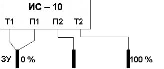
- IS-10 (microprocessor meter)
- IS-20/1 (more advanced device)
- MRU-101 (professional device
For example, you can see how grounding resistance is measured using the M-416 device. When working with it, you must proceed according to the following plan:
- First, you should make sure that there are batteries in the device compartment (3 pieces of 1.5 Volts each, giving a total supply voltage of 4.5 Volts).
- Then the device prepared for use must be positioned strictly horizontally and calibrated.
- To do this, set the handle with the pointer to the “control” position and, holding the red button firmly pressed, set the pointer to “zero”.
Measurements of protective grounding resistance with this device are carried out according to the same scheme with two electrodes.
Connection diagram for the M-416 device
After the stakes are driven into the ground, wires are connected to them according to the diagram shown (device contacts 1, 2, 3 and 4). Then the indicator of the instrument switch “Range” is set to “x1” (photo below).
Installing the handle of the M-416 device in position x1
Then you should press the control button and turn the “Reochord” knob until the arrow on the indicator shows “zero”. The number indicated on the slider scale must be multiplied by the selected range, which will result in the measured value.
Please note: In a situation where the meter reading exceeds 10 ohms, the multiplier switch (range) should be set to a higher value: “X5”, “X20” or “X100”, and then repeat all the previously described operations. The amount of resistance in this case is determined by multiplying the Reochord reading by a new scale.
To carry out measurements using this method, more “advanced” digital instruments can be used, which are characterized by ease of measurement and maximum accuracy. With their help, you can not only take readings, but also save measurement data in the internal memory.
When carrying out checks using a megohmmeter, you must act according to the instructions (it is similar to the procedures described above for the M-416). However, before checking the grounding resistance with a megohmmeter, you should know that the error in taking readings in this case will be much higher. This fact is explained by the noticeable difference between the systems under study and the usual insulation resistance. This device is more suitable for checking the insulation resistance of electrical networks of grounded equipment, the reliability of which also affects the safety of its operation.
If the insulation is broken, an unpleasant effect can be observed, which is explained by the fact that the resistance of the human body is large enough for a dangerous potential to appear on it. If you accidentally touch a bare conductor, a current will flow through your body, the magnitude of which is sufficient to cause serious injury.
Current clamp measurement
The peculiarity of the method of measuring ground resistance using standard clamp meters is as follows:
- In this case, there is no need to disconnect the grounding device from the equipment being serviced.
- Auxiliary electrodes are also not needed in this situation.
- It becomes possible to quickly control the entire process of taking readings.
The principle of measuring with current clamps is as follows: the test current flowing through the grounding conductor or bus (which in this case is the secondary winding) is assessed by the current clamps by its magnitude. After this, a reading of the voltage acting in the circuit is taken using a voltmeter.
To calculate the desired resistance, you will need to divide the resulting voltage value in volts by the current value in amperes measured using clamps.
Checking grounding in sockets
You can independently determine the grounding in an outlet in several ways. Before starting work, you will need an indicator screwdriver - it identifies the zero and phase wires. If the light comes on upon contact with the terminal, this is a phase. If the indicator does not light, it is zero.
Checking with a multimeter
Testing is carried out even if the colors match the standards. You need to work with a multimeter like this:
- Turn on the power supply to the house at the switchboard.
- Measure the voltage in the sockets. One probe is placed on phase, the second – on zero.
- Move the sensor probe from zero to the grounding conductor - PE.
- See what the tester shows. If the result has not changed, everything is fine with the system. If the readings are zero, the system needs to be grounded again.
Checking with a control light
To make a control, you will need a light bulb with a socket and two copper wires attached to it. Insulation is needed between all contacts of a homemade device. The control check is carried out according to the principle of a multimeter:
- The first probe is connected to zero, the second to phase.
- The probe moves from zero to the ground connection.
- The serviceability of the circuit is indicated by a lit lamp.
- A weak light indicates that the circuit is not working properly and that an RCD needs to be installed.
When there is wiring in the room without color indicators, you can find out the grounding like this:
- To determine zero and phase, one limit switch is output to the ground terminal, the second - in turn to other connections.
- The phase is at the point at which the indicator light comes on.
- If the lamp does not light, the PE does not work.
Indirect evidence of the absence of PE
There are several points by which one can judge the absence of PE. Owners of apartments and houses should be wary of:
- stable electric shocks from the boiler, washing machine, dishwasher, refrigerator;
- speaker noise when playing music;
- the presence of a large amount of dust near old batteries.
Testing with a pointer (digital) voltmeter
Checking the voltage value and its presence is carried out using AC voltmeters. Pointer instruments operate without a power source, while digital instruments operate in any position and are not damaged by mechanical impact.
The correct algorithm for using a voltmeter:
- The maximum permissible measurement value for the device is determined by the largest number on the scale.
- Clarification of the units of measurement of the device - microvolts, volts, millivolts.
- Connecting a voltmeter in parallel to a section of the electrical network and checking the polarity with a wire.
- Screwing the switch device wires to nuts and screws. Constant voltage models have plus and minus designations.
Contact resistance measurements
When measuring ground loop parameters, special attention is paid to the so-called “transition” zones formed over the entire area of direct joints of structural elements (including their contact with the soil and the soil itself). For these sections, the concept of “transition resistance” is introduced, which significantly affects the total value. All the measurement methods discussed above also concerned this part of the total system resistance (with the exception of the resistance of the material of the grounding conductors and pins).
By its magnitude, one can judge the speed at which a dangerous charge flows into the ground, as well as the obstacles encountered along the way. In existing systems, this component makes a significant contribution to the formation of the overall indicator for the entire ZK.
How to measure contact resistance
Before measuring grounding in transition zones, you will need to prepare a special device called a milliohmmeter. To carry out these tests, any other grounding measuring device from the same series will do (sometimes M-416 universal devices are used for this). Regardless of the type of device selected, only certified measuring equipment that has passed state verification should be used for these purposes. Otherwise, the measurements taken on the device will not be considered to comply with current standards and GOSTs.
When carrying out such measurements, the device selected as a measuring device with a charged power battery is connected with its clamp terminals on both sides of the controlled connection. Regardless of the type of circuit elements, the transition resistance between them should not exceed 0.05 Ohm. If a measurement of the grounding transient resistance carried out using this method gives an unsatisfactory result, the operation of the installation is stopped until the causes are identified and eliminated. The transient conductivity measurement diagram is shown in the photo below.
Contact resistance measurement circuit
Before checking the ground loop, you need to familiarize yourself with the existing methods for calculating it. In the vast majority of cases, they come down to simple calculations using Ohm’s law (by dividing the measured voltage by the current readings taken in the corresponding circuit).
Additional information: Before calculating the grounding resistivity, it is important to take into account all links in the emergency current flow chain, including contact zones.
The resulting result fully characterizes the design for its compliance with the standardized indicators.
How often is it measured?
The timing of checking the grounding of electrical installations is established in accordance with the following regulatory requirements:
- Visual inspections – every six months.
- Checking the quality of connections of metal elements at their joints - once a year.
Unscheduled checks of the contact resistance of the ground electrode are also possible, which are usually carried out after restoration of the circuit, as well as when serious adjustments are made to its design. Tests can also be carried out when a newly launched grounding system is put into operation.
When organizing regular or extraordinary inspections, it is necessary to be guided by the general provisions for calculating grounding resistivity.
General recommendations for measuring USG
Before constructing a grounding circuit, for example for a gas boiler, you should obtain accurate information about the area in which soil the grounding electrode will be installed. It is often suggested to refer to existing tables to determine the “p” values of soil.
However, this option with tables provides purely indicative data. Therefore, you should not rely on them. The true values of soil resistance can differ significantly.
Option #1: single-layer primer
If the soil has a homogeneous component, its resistivity is measured using the “test electrode” technique.
Structure of homogeneous soil. Under such conditions, measuring and calculating resistance is much easier than doing the same work on multi-layer soils
The method involves performing a certain procedure in two stages:
- Take a rod control probe with a length slightly greater than the depth of the design backfill.
- The probe is immersed into the ground strictly vertically to the depth of the design laying.
- The end remaining above the ground is used to measure the spreading resistance (Rr).
- The USG is determined by the formula p = Rr * Ψ.
It is advisable to perform the procedure several times at different points on the work site. Alternative measurements help achieve accurate soil resistance measurements.
Option #2: multi-layer soil
For such a situation, USG measurement is performed using the step probing method. That is, the control probe is immersed to the working depth in steps and resistivity measurements are taken at the position of each step. Calculations of the average USG are made using formulas for each individual measurement.
Multilayer soil. Under such conditions, it is necessary to calculate the resistance of each individual layer. Calculations for multi-layer soils require more work
Then, based on the climatic characteristics of the area, values for seasonal changes are found. In this way (quite complicated) the calculated values of the upper layers are obtained. The underlying layers are considered not subject to seasonal changes and therefore the calculation for them is limited to somewhat simplified measurement and calculation.
Requirements for the execution of work
Work of this kind, of course, is carried out by qualified personnel representing specialized organizations. Thus, utility services are usually responsible for the operation of power panels in residential buildings. It is permitted to make any measurements at these points only by accessing these services.
Electrical circuits are classified as dangerous systems. Despite the fact that communications in the household sector are designed for voltages less than 1000V, this voltage is fatal to humans. All necessary safety precautions must be observed when handling electrical equipment. Such measures are often simply unknown to the average person.
The following article, which contains rules and guidelines for carrying out the work, will introduce you to the features of constructing a grounding system for a bathtub in a city apartment.
Re-grounding resistance
Re-grounding is a critical element of a comprehensive electric shock protection system. It is installed on the receiving side of the supply line if there is a PE or PEN neutral wire in the connection.
Important! This requirement is valid for networks operating according to a TN scheme with a solidly grounded neutral.
As a rule, both natural and artificially created elements are used as re-grounding. However, the resistance of natural ground electrodes depends on many factors (including climatic conditions), so that over time it constantly changes its value.
In this regard, when arranging this type of grounding, preference is given to artificially created systems that have very specific indicators.
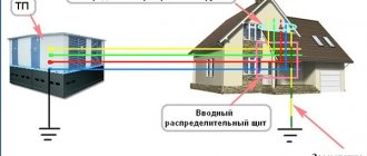
Re-grounding the cottage
The grounding wire of such a device is led out from the grounding loop towards the input panel with the main grounding bus installed in it.
The need for do-it-yourself re-grounding installed on the consumer side is explained by the following reasons:
- Its presence eliminates dangerous situations that arise in the power supply network when the neutral or grounding wire coming from the power substation breaks (photo above).
- In this case, it can work as an independent grounding, ensuring safe operating conditions for electrical installations on the consumer side.
- With it, in an apartment or private house, you can install electrical wiring with a third (grounding) conductor.
The presence of re-grounding is specifically stipulated in the PUE, certain provisions of which prescribe its mandatory installation and testing.
Checking protective grounding parameters
In addition to the obvious components of the protective “earth” system: such as a contact block, wires going to electrical installations, connection to a circuit in the ground, the earth itself plays an important role in providing protection. Accordingly, you need to make sure of the following:
- Between all elements of the circuit (pins, connecting bars, conductor into the room to the terminal block) there is a reliable electrical connection with minimal resistance.
- The voltage applied to the circuit (in the event of an accident) spreads across the physical ground with maximum current. This is only possible with good contact between the metal and the ground.
- The physical conditions of the terrain (ground) can ensure reliable contact even under poor (in terms of electrical current) conditions. Namely, drying out of the soil, cracking of the earth in the places where ground electrodes are installed.
Of course, no one takes measurements of parameters on every element of the grounding system. This will be required only in case of non-compliance with the standards, to find the so-called “weak link”.
By what principle is the protective ground loop checked?
It is necessary to create a complete analogue of a circuit that is known to work, and compare the indicators with the tested object. For this purpose, there are complexes for testing working grounding.
You can buy a set like this, but it is unlikely to pay for itself in the foreseeable future. Even taking into account that the frequency of checking grounding devices is once a year (for both residential and industrial facilities), it is easier to get one-time access to the equipment.
What is the frequency of measurements?
Before measuring the grounding resistance in one way or another, it is important to take into account the requirements of the PUE regarding the frequency of these tests. According to the main provisions of this document, they can be carried out in the following forms:
- routine examinations;
- extraordinary inspections;
- launch tests.
The frequency of each of these types of inspections is determined by the goals that they set for themselves. The frequency of inspections of the insulation resistance of station equipment is usually consistent with the inspection of the circuit breaker itself. Let's look at their different types in more detail.
Scheduled checks
The timing of planned activities is stipulated by instruction RD-34.22.121-87, as well as the requirements of the PUE. From these documents you can find out what is the frequency of visual inspection of visible parts of grounding devices, which according to them is organized at least once every six months. In addition, from the same standards it follows that at least once every 12 years, inspections of the structure must be carried out with the opening of the soil around it. Measurement of the resistance of grounding loops according to the same documents should be carried out at least once every 6 years.
Persons authorized to do so by the relevant authorities are responsible for conducting such inspections. The owner of a private house must fill out an application for them in advance with subsequent payment. Upon completion of the tests, he is obliged to provide the local energy service with a protocol for measuring the contact resistance between the elements of the closed circuit.
Extraordinary
Extraordinary measurements of circuit parameters should be carried out in the following emergency situations:
- After making changes to the design that are not provided for by the design, but affect the resistance to current flow (measurement of grounding in a private house should be carried out when moving it to another place).
- After emergency destruction and subsequent restoration of the ZK.
- Upon completion of the repair work.
The frequency of their holding is not regulated for obvious reasons.
Starting or introductory
Start-up or introductory grounding checks and resistance measurements are organized immediately after the installation of the protective circuit is completed (that is, on the eve of its delivery to the local energy service representative). To do this, you will need to invite a specialist from an electrical laboratory or other organization licensed to conduct such tests.
Based on the results of the inspection, an acceptance certificate is issued, which is the basis for the subsequent commissioning of the device and confirmation that all supply lines in private houses are grounded.
Test conditions
When organizing grounding testing activities, it is important to pay attention to the conditions in which they are supposed to be carried out. They must be taken into account at the test preparation stage, and upon completion they must be entered in a special journal. According to the requirements of current regulations (PUE, in particular), for this it is advisable to choose the summer season with sunny, dry weather, which allows you to obtain results that are closest to reality. This is explained by the fact that at such a time the soil is maintained in a fairly dry condition, corresponding to the actual operating conditions of the protective structure.
When carrying out control measurements of permissible resistances in damp autumn weather, for example, the results obtained will be significantly distorted. This is explained by the fact that soil saturated with moisture significantly increases the conductivity of the soil. In order to avoid all these difficulties and get a value close to the real value, the easiest way is to use the services of professionals. To do this, you must contact a special electrical laboratory that has a license to carry out the relevant work.
Upon arrival at the site, specialists will identify all factors and organize testing of protective equipment in accordance with the requirements of current regulations. Upon completion of the entire test cycle, they will also draw up a grounding resistance measurement protocol, a sample of which is presented below.
Protocol for testing grounding resistance
How does grounding work and why check its parameters?
Without going into details, we can say that grounding is needed to connect the electrical installation housing to the working zero. Looking at a few paragraphs above, you might think that this is absurd. In fact, what is meant is the possibility of current flowing from the protective grounding, through the physical ground (soil), to the working zero of the nearest substation. In fact, it will be a short circuit.
Accordingly, when a phase gets on the body of the electrical installation, the circuit breaker will operate, and there will be no electric shock.
Why is it necessary to check grounding resistance? To organize an emergency short circuit, a large current is required. If the resistance of the ground loop is too high, the current strength (in accordance with Ohm's law) will decrease and the circuit breaker will not operate.
Another danger of high resistance of the protective “earth” is that the resistance of the human body may be less. Then, if you touch an emergency electrical installation with your hand, you are guaranteed to be shocked by an electric shock.
When a phase appears on the body of the electrical installation, part of the voltage will go to compensate for the leakage into the physical ground. If the remaining potential exceeds 50 volts, the danger will remain.
Likewise, a circuit breaker without grounding will not disconnect a phase if it hits the housing. It will only work when the zero is connected to the phase. Complete protection is provided by installing the machine and simultaneously connecting the protective ground circuit. The RCD also significantly increases the level of safety.
And finally, about what a ground loop is.
In short, these are several metal pins (under normal natural conditions - three), deeply immersed in the ground, connected by conductors to each other and the grounding bus in the building.
Results
To summarize everything described in the previous chapters, it is necessary to note the following main points:
- Systematic checks of grounding loops make sure they are fully operational.
- When solving the problem of which instrument should be used to take readings, preference is given to special multifunctional devices that provide high measurement accuracy.
- In the process of carrying them out, it is important to adhere to generally accepted methods for determining the exact values of the measured quantities.
- The complete formula for determining the total resistance of the entire grounding structure can be found in the relevant sections of the PUE.
In addition to the article, we offer video materials for viewing that show how grounding resistance is measured using various multifunctional instruments.
In the final part of the review, we note that for a more detailed understanding of all the issues discussed, you should refer to numerous sources widely represented on the Internet. There you can also find a large number of thematic collections and video reviews that allow you to learn how to check and accurately measure the resistance of grounding structures of various types and classes.
Taking measurements
And yet, in the question of how to measure grounding resistance, it is better to use a megohmmeter rather than a multimeter. The best option is considered to be a portable electrical measuring device M-416. Its operation is based on the compensation measurement method; for this purpose, a potential electrode and an auxiliary ground electrode are used. Its measuring limits are from 0.1 to 1000 Ohms, the device can be operated at temperatures from -25 to +60 degrees, power is provided by three 1.5 V batteries.
And now step-by-step instructions for the entire process on how to measure the resistance of the ground loop:
- Place the device on a horizontal, flat surface.
- Now calibrate it. Select the “control” mode, press the red button and, while holding it, set the arrow to the “zero” position.
- There is also some resistance in the connecting wires between the terminals; to minimize this influence, place the device closer to the ground electrode being measured.
- Select the desired connection diagram. You can check the resistance roughly; to do this, connect the terminals with jumpers and connect the device using a three-terminal circuit. For accurate measurements, the error caused by the connecting wires should be eliminated, that is, the jumper is removed between the terminals and a four-clamp connection diagram is used (by the way, it is drawn on the cover of the device).
- Drive the auxiliary electrode and probe rod into the ground to a depth of at least 0.5 m, keep in mind that the soil must be dense and not bulky. To hammer in, use a sledgehammer, the blows should be straight, without swinging.
- Clean the place where you will connect the conductors to the ground electrode with a file to remove paint. Use copper conductors with a cross section of 1.5 mm2 as conductors. If you use a three-clamp circuit, then the file will act as a connecting probe between the ground electrode and the terminal, since a copper wire with a cross-section of 2.5 mm2 is connected on its other side.
- And now we move on directly to how to measure grounding resistance. Select the range “x1” (that is, multiply by “1”). Press the red button and turn the knob to set the arrow to zero. For larger resistances, it will be necessary to select a larger range (“x5” or “x20”). Since we chose the “x1” range, the number on the scale will correspond to the measured resistance.
It is clear how grounding is measured in the following video:
How to take grounding measurements with a multimeter
And if everything is clear with the modeling and calculations of grounding in the program, then it is worth paying special attention to the preparation and organization of measurements of the grounding loop directly at a specific facility. First of all, you need a phase conductor
You can sign up for it either from a nearby outlet, or run a separate wire from the metering panel. In both cases, the end point is the socket, in which you need to determine the phase with an indicator screwdriver and mark
First of all, you need a phase conductor. You can sign up for it either from a nearby outlet, or run a separate wire from the metering panel. In both cases, the end point is the socket, in which you need to determine the phase with an indicator screwdriver and mark it.
Next, you will need a plug in which one wire is inserted and connected to one pin contact. Here you also need to note the contact you are using. This wire is connected to the contacts of the socket block (at least two) and is broken by a circuit breaker along the way. The second wire, connected to the ground loop, is also inserted into the socket block and connected to other contacts.
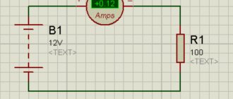
In this way, it is possible to relatively safely measure the potential difference in the area of the connected kettle. To do this, insert the plug into the socket so that the engaged contact of the plug is connected to the phase in the socket. We connect the kettle to the socket block, check whether the machine is on, and turn on the kettle’s load. First you need to prepare a multimeter to measure alternating voltage. After connecting the kettle to the phase-ground network, the measurement is carried out with probes through the contacts of a free socket in the block. Turn off the kettle and write down the resulting voltage U(kettle).
When measuring current, the sequence is the same, only the circuit breaker must be turned off (the kettle is on, but not working). The multimeter is switched to AC current measurement mode. The measurement is made by closing the circuit with probes through the contacts of the circuit breaker. This is not a safe measurement, so using cheap multimeters with flimsy probes is not recommended. For safer measurements in the circuit, you need to replace the kettle with a less powerful device with a resistance of about 200 Ohms. Accordingly, the current in the circuit will not exceed 1 A, and the potential removal through the grounding will decrease. Having measured the current in the circuit, we write down the result I.
All that remains is to measure the voltage in the house U (≈ 230 V). Knowing the three obtained values, the resistance of the ground loop is determined by the following formula: R = (U - U(kettle)) / I - 2 (Ohm). 2 Ohm - grounding resistance of the transformer neutral.
Standards for each type
In order to understand what regulatory and operational indicators should be for each type:
- For electrical installations. Ground resistance measurements should be carried out in close proximity to the substation. Depending on the load, this figure can be 60, 30 or 15 Ohms. It is also worth considering natural grounding electrodes - for them these values should be 8, 4 or 2 Ohms, respectively. All three quantities depend on the network voltage. 60 and 8 Ohms are allowed for a single-phase network of 200 volts. 30 and 4 Ohms - for three-phase with a voltage of 380 volts. The minimum values (15 and 2 Ohms) are for 660 volts. During operation, the resistance of the ground loop should also not fall below the values described in the paragraph above.
- For a distribution point or substation. For installations with voltages above 100 kilovolts (100 thousand volts), the grounding conductivity during the commissioning of the network and during its operation also remains unchanged and is 0.5 Ohm. In this case, the mandatory requirements for testing are a solid grounding type and connected to a neutral circuit. There are also standards for less powerful installations, in which the voltage lies between 3 and 35 kilovolts. In this case, you need to divide 250 by the calculated ground fault current - the resulting value will be the required resistance in Ohms. The indicator, according to PTEEP, should not exceed 10 Ohms in any case.
- For overhead power lines. It is calculated depending on the conductivity of the soil on which the power line supports stand:
- for soil with a resistivity of less than 100 Ohms per meter - 10 Ohms;
- with a resistivity of 100...500 Ohms per meter - 15 Ohms;
- with a resistivity of 500...1000 Ohms per meter - 20 Ohms;
- with a resistivity of 1000...5000 Ohms per meter - 30 Ohms.
For power lines with a current voltage of less than 1000 volts - up to 30 Ohms (for supports with lightning protection). Otherwise, the resistance should be 60, 30 or 15 ohms for networks with voltages up to 660, 380 or 220 volts, respectively.
General procedure for technical inspection
The main approaches to checking the quality of grounding are based on well-known methods for measuring its resistance to current spreading to the ground. When assessing this value, both individual elements and contact zones of the grounding loop, which starts from the protected area and ends at the point of contact of the ground electrode with the ground, are subject to control
During the work, special attention is paid to parts of the grounding structure that have direct contact with the ground and are subject to increased corrosive effects
The fact is that as a result of the destruction of the metal in the contact zone, its electrical conductivity decreases and the resistance to current spreading increases. As a result, the reliability indicators of the charger, as well as the efficiency of its operation, noticeably deteriorate. To check and evaluate the condition of metal transitions of individual grounding elements, special measuring instruments (ohmmeters) are used. They provide readings with an acceptable error.
Please note that the specified verification procedure is carried out, as a rule, as part of work operations that involve a comprehensive test of grounding devices for their compliance with the requirements of the PUE. Carrying out the test is closely related to the measurement of the current flowing in the circuit, in accordance with which the value of the normalized PTEEP resistance is calculated
If necessary, this value can be reduced by increasing the area of contact with the ground or changing the electrical conductivity of the soil. For this purpose, additional metal rods are added to the ground loop design, or the salt concentration in the area of its direct contact with the soil is increased.
Carrying out the test is closely related to the measurement of the current flowing in the circuit, in accordance with which the value of the normalized PTEEP resistance is calculated. If necessary, this value can be reduced by increasing the area of contact with the ground or changing the electrical conductivity of the soil. For this purpose, additional metal rods are added to the ground loop design, or the salt concentration in the area of its direct contact with the soil is increased.
The examined grounding circuit is considered to comply with the requirements of the PUE and safety standards only in cases where the total resistance of all its elements does not exceed a certain value. Based on the results obtained during the inspection process, representatives of special measuring laboratories draw up a report on the condition of the system being inspected and issue permission for its further operation.
Appliances used
Due to the fact that a household tester is not capable of providing high voltage, it cannot be used for this procedure. Usually they use devices that have been produced by industry for a long time, but there are also new models that work using new electronic technologies. All of them are characterized by low current consumption from the built-in power supply. Among them, the following models are worth noting:
- F4103-M1 is a popular device for performing work on measuring contours of various geometric shapes and sizes. The measurement error of the device is 4%, and the current frequency is from 265 to 310 Hz. The device is powered by 9 A373 batteries, and the current consumption does not exceed 160 mA.
- M-416 - this measuring device has been in operation for quite some time. It is distinguished by high accuracy of readings taken and reliability in operation. In addition to measuring ground resistance, this meter can determine soil resistivity. The measurement range is from 0.1 to 1000 ohms.
- The Fluke 1625−2 GEO is a more modern instrument that can measure using just the clamps. In this case, grounding electrodes are not used. In addition to measuring ground resistance, you can also check lightning protection.
In addition, the following models can be noted: MRU-101, IS-20/1, IS-10, etc.
Why measure resistance?
Measurements are necessary to determine the resistance value of the ground loop. The resistance of the insulating layer is also measured. Indicators must be within the standards developed by regulatory authorities. If necessary, the resistance of the grounding device is reduced by increasing the contact surface or improving the overall conductivity of the medium. To achieve the desired result, increase the number of electrodes or create a salty environment in the soil around the ground electrode.