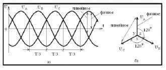
Scheme of Connecting a Generator to the Home Network
The number of phases that will be used in the generator depends on how many phases come from the main power supply.
Just one turn of the switch or operation in fully automatic mode and you will feel calm and safe. Generator autostart The most complete way to switch the load is using an automatic transfer switch.
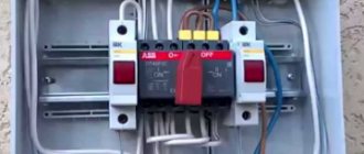
Here it also makes sense to use partial automation, since semi-automatic machines are inexpensive. 220V home generator with autostart system from Kirill Plisov. It will be interesting to read:. The nuances are that when connecting the gas generator to the network, it is necessary not only not to confuse the phase-zero polarity, but also in some RCDs the power source is connected to the upper terminals, and the load to the lower ones. Otherwise, you can receive large fines for illegal tapping. At the location of the electrical panel.
Do not wear loose clothing, as the fan inside can pull in the fabric and other items of clothing. Connecting a single-phase generator to a three-phase network at home will not be a problem, the main thing is that the generator’s power is enough to consume the most important consumers in the house.
Preference should be given to a brushless design with better current characteristics and less radio interference. ATS circuit with two contactors and a phase control relay
How to make a simple auto-switching circuit for a generator
It is inconvenient to always press the switch when starting a backup unit, so a simple automatic switching unit is assembled. This is not an autostart system; its task is to mechanically change the input between networks - the mainline and the mini-station. Starting/stopping the engine still needs to be done manually.
What you will need:
- 2 starters (contactors) - KM1 and 2 with cross connection. Their executive elements are contacts: power (KMk), normally closed (KMnz);
- For full automation it is necessary to install a time relay for warming up.
While the line is operational, KM1 closes KMk1, while KM1nz1 and KM1nz2 are uncoupled. When disconnected, the former open and the latter close. At start, after the relay delay has expired, current appears on KM2, KM2 closes, and backup power begins to be supplied.
When the main power appears, KM1 is activated, KM1nz1 and 2 are disconnected, and KM2 is de-energized. KMk2 open, KMk1 close. There is a switch to the main line. You just need to remember to turn off the backup device itself.
How to connect a single-phase generator?
There are several connection options. The first is connecting the unit to a designated group of consumers.
Connecting voltage in manual mode
The second method is to use a rocker switch (switch) in 3 positions 1-0-2, in other words, in the 1st position, power is taken from the centralized (city) electrical network, switch position 0 - the electrical circuit is turned off, in position 2 - home connected to a backup source of electricity, in this option it is a gas, gasoline or diesel generator.
Without delving too deeply into the structure of the devices, we only note that the design of a changeover switch or a 3-position switch is quite simple and includes stationary contacts to which the wiring is connected (consumer-city-device generating electricity), and movable contacts that switch the consumer from the centralized power grid to the generator and back.
When switching a 3-phase load, the city-consumer will switch 3 phases, in other words, 3 city phases A-B-C go to the switch, and the same 3 phases go to the consumer.
When switching the consumer to the generator, we need to do it in such a way that all 3 phases receive electricity.
In this case, it is necessary to slightly modify the switch-switch - make a jumper between phases A-B-C on the side connecting the device that generates electricity. Now, when the consumer switches to the generator, electric current will flow to all 3 phases.
Connecting the consumer via contactors
The third way to connect a consumer to a single-phase generator is to use contactors. With this option, 2 contactors are used, one to power the consumer from a centralized network, the 2nd contactor is needed to connect the consumer to a backup source of electricity - a gas, gasoline or diesel generator. This method is acceptable when using automatic backup power (ABP).
When the consumer is powered from a centralized network, all 3 phases connected to the contactor go to the consumer. When connecting a generator, as in the version with a 3-position switch, at the contactor terminals in the area where the cable from the generator is connected, we need to slightly modify the switch switch - place a jumper between phases A-B-C.
When operating a single-phase generator, it is necessary to take into account that if there is 3-phase equipment, it must be disconnected from the power supply while the generator is operating, since this can cause breakdown of these devices.
Connecting three-phase models
Connection via an additional distribution machine. The circuit diagram for connecting the machines from the power line and the generator is almost the same, which makes it possible not to change anything in a functioning 3-phase electrical network. This approach to introducing an individual home into the network is considered the most reliable and ensures the efficient operation of the equipment connected to it.
To implement it, you will need to take certain actions.
- Turn off the 380 V input circuit breaker, stopping the supply of current to the house.
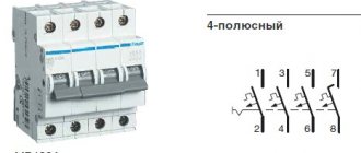
- Install a new 4-pole circuit breaker in the panel, the output terminals of which are connected by pieces of wire to the input terminals of all linear devices.
- The generator output cable with 4 wires (3 phases and neutral) is fed to the new circuit breaker, and each of them is connected to the correct terminal.
- If a residual current device is installed further in the diagram, when performing switching, the wiring of the wires connected to it (each of 3 phases and zero) is provided.
Connection via switch
A changeover switch (reversing switch) is the same switch, only with three positions.
When using it, the busbars from the generator are connected to one group of poles, and the supply wires from the power line are connected to another.
The central group of contacts of the switch, the wires from which go directly to the consumer, are sequentially transferred towards the input from the explosive or to the generator supply. In the middle position of the switch, the entire house is completely de-energized.
Connection diagrams
Having dealt with the auxiliary issues, they proceed directly to connecting the generator to the service line.
Connection via an additional distribution machine
The circuit diagram for connecting the machines from the line and the generator is almost the same, which allows you to not change anything in the existing three-phase electrical network. This approach to connecting a private home to the network is the most reliable and guarantees the successful operation of the equipment connected to it. To implement it, you will need to perform the following operations:
- Turn off the 380 Volt input circuit breaker by de-energizing the home network.
- Install a new 4-pole circuit breaker in the panel, the output terminals of which are connected by sections of conductors to the input contacts of all linear devices.
- The cable from the generator output with 4 cores (3 phases and zero) is fed to the new machine and each of them is connected to the corresponding terminal.
If an RCD is installed further in the diagram, when making switching, the wiring of the conductors connected to it (each of the 3 phases and zero) is taken into account.
Connection via switch
A changeover switch is the same switch, but has three positions. When using it, the busbars from the generating device are connected to one set of poles, and the supply wires from the high-voltage line are connected to another. The central contact set of the switch, the conductors from which go directly to the load, is alternately thrown towards the input from the explosive or to the generator supply. In the middle position of the switch, the entire home network is completely de-energized.
Automatic switching circuit
It is possible to get rid of the need to manually select a power source by using an automatic switching circuit for the load connected to it. At a minimum, it includes a control module and two cross-connected starters (contactors). The first of these nodes, manufactured on the basis of a microprocessor, semiconductor transistors or analog microcircuits, performs the following functions:
- recognition of a situation with a loss of electricity in the main supply line;
- subsequent disconnection of the consumer from it;
- switching it to a tap from a 3-phase generator.
Through a socket
To connect the generator to the home network through an outlet, you will need to carefully familiarize yourself with the features of using this method. Despite its simplicity and ease of connection, this option has many negative aspects, expressed as follows:
- the need to constantly ensure that the introductory machine is turned off;
- the need to purchase a special 4-pole socket designed for high currents;
- restrictions on the load connected to the generator.
The plug-in method is the worst of all possible. Its use is unacceptable under any conditions.
{SOURCE}
How to connect a single-phase generator to a three-phase network.
How to connect a generator to the house ? It would seem that it could be simpler, start the generator, connect it to the house and that’s it, we live as before))). In previous articles, we have already looked at how to connect a generator to the house and the main mistakes that can lead to big troubles, the smallest of which is the failure of the generator.
In this article I would like to consider the issue of connecting a single-phase generator to the house
, in which all electrical wiring is designed and executed for a three-phase network. Oddly enough, many electricians, even with decent work experience, fall into a stupor and begin to reinvent the wheel))).
The most optimal solution when connecting a generator to the house
,
This is when, even at the stage of construction and electrical installation work, a separate group of the most critical consumers is provided for backup power supply. As a rule, some lighting, heating equipment, some sockets, and a security and fire alarm are connected to this group. This method is good because you can get by with a relatively low power generator.
But quite often, in 90% of cases, people only remember about purchasing and then connecting a generator to the electrical network at home when power outages begin.
In order for everyone to understand what goes where, we will try to explain everything in simple and understandable language, without the use of special terms and various abstruse language.
How to connect the generator?
The electric generator can be connected in two ways:
- Through a switch (connection to the panel);
- Using automatic or semi-automatic reserve input.
The generator is connected to the panel using a changeover or reversing switch:
- Before installing it, a cable is laid, depending on the power of the generator.
- Then the switch itself is installed in the panel in a special box, protecting it from rust and corrosion.
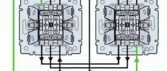
- After that, all that remains is to connect the switch (the main network cable is located on top, the private circuit of the house is in the center, and grounding is below), and start the generator.
Connecting a generator with a semi-automatic automatic transfer switch involves installing two semiconductors in protective boxes that are connected to each other. When the lights go out, you need to start the backup power source, then there will be an automatic transition from the main network to the generator.
Automatic reserve input means turning on the generator automatically, without any intervention.
How to connect a gas generator
The use of an electricity generator in the house can be done in 2 ways: by connecting electrical appliances directly to the unit’s outlet through an extension cord and by integrating the generator into the general electrical network of the room. If the first method is suitable for infrequent and short-term use (for example, in the country or in nature), then the second method is used during long power outages or in the absence of electricity at the site. In this article we will talk about generators as the main or backup power source in a country house or in any other building (in a store, workshop, production facilities) and about their correct connection.
Before connecting the power plant to the home network, you need to solve several problems:
- Understand how much backup power is needed. Assess how critical a power outage will be or whether constant power is required (for example, if a server is running in the house or just expensive equipment)
- Determine the location for the unit, taking into account safe operation and close proximity to the connection point.
- Calculate the required power for all electrical appliances in the house that can be used. It is also necessary to take into account possible losses on the line and leave a small power reserve (20–30%).
- Decide whether to use automatic or manual control.
The use of automatic control and protection systems will be more expensive due to the cost and the need for additional measures to protect the wiring from strong voltage surges when switching from the general network to the generator and vice versa. A more gentle measure would be to use manual control when you make the switch yourself.
When connecting the generator, it works with 3 networks:
- the general network through which the house receives electricity;
- home internal network;
- generator wiring.
Why can't you connect the generator through an outlet?
Connecting via a connector is a fairly simple procedure, but you should not give it preference when connecting a generator to a general house electrical network, as this entails many problems:
- Possibility of overload at the connection point - since the entire load falls entirely on only one outlet, this is fraught with rapid overheating, melting and even fire.
- The absence of a separate circuit breaker in the power line that would be responsible for safety and emergency shutdown in the event of dangerous situations.
- Human inattention - when turning on the unit, sometimes they forget to turn off the input machine. This entails overload and activation of the protection unit
- Possibility of generator breakdown when starting electric current through the line and reaching the contacts of a working unit. In this case, major repairs or complete replacement of the power plant may be required.
Methods for connecting a generator to the network
There are 3 ways to properly connect a power plant to a home network.
Changeover (reversible) switch (manual control)
This is a device that will be responsible for a secure connection. Advantages of this type of control:
- Simplicity of design - the switch is equipped with 3 modes - 1-0-2. 1 — power from the general network, 0 — closure of all contacts, 2 — power from the generator.
- Simplicity of connection - the general network is connected to the upper part of the switch on the left side, and the generator on the right. At the bottom, jumper wires form the input to the common house line. For system security, it is recommended to add machines to each line. They ensure system shutdown during overloads and other critical situations.
- Affordable price - switches of this type cost around 500 rubles.
Connection options
Before moving on to considering specific systems, it is worth understanding why it is necessary to make a special input system. The fact is that many users simply connect the generator through a connector - they say, anyway, the electricity disappears every few months, and there is no point in spending time and money on arranging a connection point.
But connecting through an outlet is fraught with many problems:
Connecting via an outlet can only be considered as a temporary option
Option 1 - connection via changeover switches
In this case, the following generator connection diagram will be used:
A very simple and understandable design that you can do yourself
The main element that will be responsible for a safe connection is the changeover switch; its design has the following features:
The changeover switch has three positions
- Simplicity . The switch has three modes: 1-0-2. In the first position, the system is powered from a stationary network, in zero all contacts are opened, and in position “2” energy will be supplied from the generator;
- Easy to connect . Below is a simple instruction, following which anyone can do the work with their own hands, even if they have never worked with electrical networks. The work does not require electrician skills or special equipment;
- Low cost . A reversible switch (as it is also called) will cost you about 500 rubles, the price is more than affordable.
Let's figure out how to connect the generator to the house:
If the walls do not hold sounds well, then you need to additionally soundproof them using special mineral wool or polystyrene foam.
Below, the entrance to the house is arranged using jumper wires.
The system startup process is carried out in the following sequence:
- The machine at the main line input ;
- The reversing switch switches to power from the generator;
- Automatic load switches off;
- The generator starts . For full operation, the equipment warms up for 3-4 minutes;
- Power is supplied to the changeover switch;
- Automatic load switches on.
Connection diagram of a single-phase generator to a three-phase network
Let's consider the key points of connecting a single-phase generator to a three-phase network. Recently, this topic was created on the forum, and I decided to give a more detailed answer, as well as discuss this issue on the blog, since many readers do not visit the forum.
Connecting a single-phase generator is relevant for private houses and cottages that want to have an independent power source.
Many luxury houses (cottages) have three-phase input due to high power consumption. Here the question may arise: what kind of generator is needed? A three-phase generator of the required power suggests itself.
Generator for a private home
Is a three-phase generator really necessary?
I will not give a definitive answer to this answer, however, I assume that a single-phase generator will be cheaper than a three-phase one.
I have already told you why three-phase input is bad. The main problem is that it is very difficult to achieve uniform phase distribution. Perhaps the generator does not tolerate operating modes very well when there is constant phase imbalance.
But how can we convert our three-phase shield into a single-phase one?
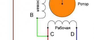
Everything is very simple. Scheme for automatically connecting a single-phase generator to a three-phase network:
Connection diagram of a single-phase DG to a three-phase network
For this we need only 2 contactors, not counting the auxiliary elements.
In normal mode, consumers are connected to a three-phase network through the KM1 contactor. If the main power is turned off, the generator starts. Starting can be done using the additional contact of the KM1 contactor. Contactor KM1 is turned off, and contactor KM2 is turned on and combines phase 3 into one.
If you do not need automatic starting of the generator, then instead of this ATS you can use, for example, a cam switch for the appropriate power. The connection diagram is similar to KM2. Here we must use either two manual switches or 1 switch, and turn off the supply network with an input circuit breaker.
Which solution is preferable? The choice is yours.
I also advise you to review my old articles:
I recommend reading:
“Scheme for connecting a single-phase generator to a three-phase network”
“At the same time, do not forget that the power of a single-phase generator will be at least 2 times greater than a three-phase one.”
They didn’t write about the zero cross section.
I don't understand the question about power.
The cross section of the zero is not less than the cross section of the phase wire. For example, VVG-3×16.
Why will the power of a single-phase generator be at least 2 times greater than a three-phase one?
About zero. Which cable to lay from the automatic transfer switch to the distribution board with a three-phase input with a power of 15 kW. Emergency diesel is acceptable at 15 kW.
Single-phase diesel respectively.
You calculate the current, select the machine, and then select the cable cross-section. At 15kVA - VVG-3×16
But then how will there be power from the network in three-phase mode?
The supply cable from the three-phase network will be your own, for example SIP4-4×16 or SIP4-4×25.
from the support to the ATS and from the diesel engine to the ATS everything is already clear. What kind of cable is placed from the AVR to the distribution board? And why is the power of a single-phase generator 2+ times greater than the power of a three-phase generator?
After AVR, you will have group lines. There should be no intermediate shields.
When you transfer all electric motors to one phase, the total Kc should decrease, therefore the power of the single-phase generator will be Pantryk:
There should be no intermediate shields.
If the ATS is built into a panel with group devices, then yes, there will be devices right away. And if the AVR is a separate design. It includes two cables (one from the diesel engine and one from the support) and one goes to the panel with group devices. So I’m talking about the zero of such a cable. Or for example, I have a two-story mansion and the allocated power is 30 kW, and I set the diesel to the same 15 kW. At the same time, I have a switchboard for the second floor. It is three phase. It comes with a 5x4 cable. And now we apply common-mode voltage to all phases. What happens to zero? In the particular case with one input distribution board, nothing bad will happen because The tire section is quite sufficient
But in the general case of using a single-phase generator in a three-phase network, it is worth paying attention to the zero cross-section in three-phase cables and groups
I did not consider all the nuances in detail, and did not become attached to a specific object. We always need to look at what currents we will have and, depending on them, select machines and cable sections.
If you have a project, we can discuss it in more detail on the forum.
CONNECTING A GENERATOR TO A PRIVATE HOUSE - VIDEO
This type of connection is strongly recommended by experts, since it is not only very reliable, but also provides the necessary comfort.
For those who know electrical engineering at a professional level, this method is better than all others. It involves the installation and use of an automatic transfer switchboard (ATS). As soon as the centralized power supply is turned off, the controller or relay of the ATS unit will start an autonomous source without human intervention and after some time transfer the load to it (Fig. 2).
If you understand that your qualifications are not high enough, then you should limit yourself to the stage of connecting the ATS unit, and involve a specialized organization in the assembly of this shield. This will protect the house from incorrect circuit solutions. For example, the absence of a mechanical interlock for the simultaneous activation of a pair of contactors can lead to parallel operation of the generator and the network, the consequences of which will be disastrous for both the equipment and the building.
Mini-power plants equipped with an electric starter, which, upon receiving a signal from the ATS, will start the generator, have the ability to connect via an automatic transfer switch. If the purchased model of an autonomous source is designed only for manual start-up mode, then the AVR. of course, will switch the consumer circuit to an autonomous source and back when the centralized power supply is restored. But you will have to turn the generator on and off manually. In this situation, it is more advisable to limit yourself to connecting the generator through a three-position switch-disconnector.
When contacting third-party contractors or making your own connection, you must strictly follow the manufacturer’s recommendations for installing and operating the generator, including the requirements for the presence of protective grounding. Only technically correct connection using reliable switching and protective devices guarantees long-term and trouble-free service of the entire in-house electrical network.