Before choosing a connection diagram for a single-phase asynchronous motor, it is important to determine whether to reverse. If for proper operation you will often need to change the direction of rotation of the rotor, then it is advisable to organize reversal using a push-button station. If one-way rotation is enough for you, then the simplest circuit without the possibility of switching will do. But what to do if, after connecting via it, you decide that the direction still needs to be changed? Single-phase 220V motor - how to change the direction of rotation?
Single-phase 220V motor - problem statement
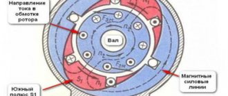
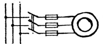
Let's assume that an asynchronous single-phase motor, already connected using a starting-charging capacity, initially has a shaft rotation directed clockwise, as in the picture below (single-phase motor 220V)
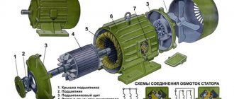
Single-phase motor connection diagram
Let's clarify the important points:
- Point A marks the beginning of the starting winding, and point B marks its end. A brown wire is connected to the starting terminal A, and a green wire is connected to the ending terminal.
- Point C marks the beginning of the working winding, and point D marks its end. A red wire is connected to the initial contact, and a blue wire is connected to the final contact.
- The direction of rotation of the rotor is indicated by arrows.
We set ourselves the task of reversing a single-phase motor without opening its housing so that the rotor begins to rotate in the other direction (in this example, against the movement of the clock hand). It can be solved in three ways. Let's take a closer look at them.
Variable network: 380V to 220V
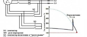
To connect a three-phase asynchronous motor to a 220V power supply, it is necessary to use one or two capacitors to compensate for the missing phase: operating and starting. The direction of rotational movement depends on what the third winding is connected to.
To force the shaft to rotate in the other direction, winding No. 3 must be connected using a capacitor to a toggle switch with two positions. It should have two contacts connected to windings No. 1 and No. 2. Below is a detailed diagram.
Such a motor will play the role of a single-phase motor, since the connection was made using one phase wire. To start it, you need to move the reversing toggle switch to the desired position (“forward” or “backward”), then move the “start” toggle switch to the “on” position. At the moment of startup, you must press the button of the same name - “start”. You need to hold it for no more than three seconds. This will be enough for overclocking.
Option 1: reconnection of the working winding (single-phase motor 220V)
To change the direction of rotation of the motor, you can only swap the beginning and end of the working (permanently on) winding, as shown in the figure. You might think that to do this you would have to open the case, take out the winding and turn it over. There is no need to do this, because it is enough to work with the contacts from the outside:
- There should be four wires coming out of the housing. 2 of them correspond to the beginnings of the working and starting windings, and 2 to their ends. Determine which pair belongs only to the working winding.
- You will see that two lines are connected to this pair: phase and zero. With the motor turned off, reverse the phase by changing the phase from the initial winding contact to the final one, and zero - from the final to the initial one. Or vice versa.
Connection diagram for a single-phase motor
As a result, we get a diagram where points C and D change places. Now the rotor of the asynchronous motor will rotate in the other direction.
Connection diagram for a three-phase motor via a capacitor
Here, the voltage of 220 volts is distributed into 2 series-connected windings, where each is designed for this voltage. Therefore, the power is lost almost twice, but such an engine can be used in many low-power devices.
The maximum power of a 380 V motor in a 220 V network can be achieved using a delta connection. In addition to minimal power losses, the engine speed also remains unchanged. Here, each winding is used for its own operating voltage, hence the power.
It is important to remember: three-phase electric motors have higher efficiency than single-phase 220 V motors . Therefore, if there is a 380 V input, be sure to connect to it - this will ensure more stable and economical operation of the devices. To start the motor, you will not need various starters and windings, because a rotating magnetic field appears in the stator immediately after connecting to a 380 V network.
Useful: Wiring diagram for a motion sensor for lighting
Option 2: reconnecting the starting winding (single-phase motor 220V)
The second way to organize the reverse of a 220 Volt asynchronous motor is to swap the beginning and end of the starting winding. This is done by analogy with the first option:
- Of the four wires coming out of the motor box, find out which of them correspond to the starter winding taps.
- Initially, end B of the starting winding was connected to the beginning C of the working winding, and beginning A was connected to the starting-charging capacitor. You can reverse a single-phase motor by connecting the capacitance to terminal B, and the beginning of C to the beginning of A.
Reconnecting the starting winding
After the actions described above, we get a diagram as in the figure above: points A and B have swapped places, which means the rotor began to turn in the opposite direction.
Online calculation of motor capacitor capacity
| Enter data for calculating capacitors - motor power and efficiency |
There is a special formula that can be used to calculate the required capacity accurately, but you can easily get by with an online calculator or recommendations that are derived from many experiments:
The working capacitor is taken at the rate of 0.8 μF per 0.1 kW of engine power; The launcher is selected 2-3 times more.
Capacitors must be non-polar, that is, not electrolytic. The operating voltage of these capacitors must be at least 1.5 times higher than the network voltage, that is, for a 220 V network we take capacitors with an operating voltage of 350 V and higher. To make starting easier, look for a special capacitor in the starting circuit. They have the words Start or Starting in their markings.
Starting capacitors for motors
These capacitors can be selected using the method from smallest to largest. Having thus selected the average capacity, you can gradually add and monitor the operating mode of the engine so that it does not overheat and has enough power on the shaft. Also, the starting capacitor is selected by adding until it starts smoothly without delays.
During normal operation of three-phase asynchronous electric motors with capacitor start, connected to a single-phase network, it is assumed that the capacitance of the capacitor will change (decrease) with increasing shaft speed. At the moment of starting asynchronous motors (especially with a load on the shaft) in a 220 V network, an increased capacity of the phase-shifting capacitor is required.
Option 3: changing the starting winding to the working winding, and vice versa
It is possible to organize the reverse of a single-phase 220V motor using the methods described above only if taps from both windings with all beginnings and ends come out of the housing: A, B, C and D. But there are often motors in which the manufacturer intentionally left them outside only 3 contacts. In this way, he protected the device from various “homemade products”. But still there is a way out.
Changing the starting winding to the working winding, and vice versa
The figure above shows a diagram of such a “problematic” motor. It only has three wires coming out of the housing. They are marked with brown, blue and purple colors. The green and red lines corresponding to the end B of the starting winding and the beginning C of the working winding are interconnected internally. We will not be able to access them without disassembling the engine. Therefore, it is not possible to change the rotor rotation using one of the first two options.
In this case, do this:
- Remove the capacitor from the initial terminal A;
- Connect it to the final terminal D;
- From wires A and D, as well as the phase, taps are made (you can reverse it using a key).
Single-phase motor connection diagram
Look at the picture above. Now, if you connect the phase to tap D, the rotor rotates in one direction. If the phase wire is transferred to branch A, then the direction of rotation can be changed in the opposite direction. Reversing can be done by manually disconnecting and connecting the wires. Using a key will help make the job easier.
Reversing single-phase capacitor motor with remote control
Digital reverse circuit of a single-phase asynchronous motor on a PIC12F629 microcontroller
This simple digital device was developed to control a single-phase asynchronous electric motor type 6AE80 with a rated power of 1100 W. One of the conditions was the presence of a wired remote control with a cable 5-6 meters long, light weight of the remote control and low-voltage control (for the operator’s electrical safety). The device can be used with any single-phase asynchronous electric motor, but the power of the motor must be taken into account. For more powerful motors, it may be necessary to use electromagnetic relays in the circuit that can switch more current.
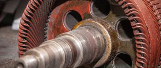
Electric motor 6AE80
Most often, electricians make such devices based on electromagnetic starters, which are almost powerful electromagnetic relays with 220-volt windings. For example, common contactors such as PML-1100. This is the most common solution, but for our purposes it has a number of disadvantages. The first is the large dimensions of the device on electromagnetic contactors, and the second is the need to pull large cross-section power wires to the control panel (push-button panel), through which a relatively large current flows and a dangerously high mains voltage of 220 volts is present. The picture below is a photo of one of these devices:
We see that such a device is comparable in size to the size of the electric motor itself.
I decided to develop a small-sized digitally controlled device using an inexpensive 8-pin PIC12F629 microcontroller.
The use of a microcontroller made it possible to control the motor with just two buttons (instead of the usual three buttons in reverse on starters). In this case, the operator does not need to think about stopping the engine before changing the direction of rotation - this is taken care of by the program “hardwired” into the microcontroller.
The photo shows my engine control panel. The remote control is connected to the controller unit with a soft, high-quality cable 6 meters long (If necessary, the cable length can be increased). A microphone cable with two cores and a screen is used. The cable has a diameter of 6 mm (in insulation). This cable is used in audio engineering to connect microphones. In principle, any three-core wire can be used. I used a microphone because it is of high quality, resistant to bending and breaks, and is designed for use in “extreme” conditions of live concerts.
Microphone cable (one option)
The control panel has two buttons. The green button is forward rotation, the red button is reverse, that is, rotation in the opposite direction (it should be noted that the directions of rotation are conditional).
If the engine is stopped, pressing any of the buttons starts the engine in the corresponding direction. If you press any of the buttons while the motor is rotating, the engine turns off.
On the body of the control panel there is a ring designed so that the remote control can be hung on the wall or on the operator’s neck (customer’s request). The motor is used with a gearbox in a pipe bending machine.
The housings of the control panel and the controller itself were designed in the SolidWorks 3D modeling program and printed on a 3D printer.
The body of the push-button panel (left) and controller (right), printed on a 3D printer.
Control controller mounted on the plastic cover of the junction box of the 6AE80 engine.
Changing the direction of rotation of a single-phase asynchronous motor
There are several types of asynchronous single-phase electric motors. This article is about capacitor start motors. such an electric motor has two windings - working (R.O.) and starting (P.O.). the working winding is connected directly to the 220 volt network, and the starting winding is connected through a special starting capacitor. The capacitor allows you to create a phase shift of the alternating current in the starting winding relative to the current in the working winding.
In this diagram (and in the distribution block of our 6AE80 engine), the beginning and end of the working winding are designated as U1 and U2, and the beginning and end of the starting winding are designated Z1 and Z2. In order to change the direction of rotation, it is enough to swap the beginning and end of any of the windings. Usually reverse is used along the working winding, but it makes absolutely no difference which winding beginning and end are changed. We will change the terminals of the working winding, that is, U1 and U2. So, the circuit for reverse switching will look like this:
It should be borne in mind that changing the direction of rotation of such an engine is possible only at the moment of its start. In this case, the engine armature must be stationary. If you switch the winding and apply power to the motor without waiting for its armature to stop rotating, the motor will start in the same direction in which it was rotating before, regardless of whether the winding is turned on.
Schematic diagram of the motor control controller
The printed circuit board is laid out in the DipTrace program, so the circuit diagram is also drawn in the DipTrace circuit editor. To enlarge the diagram, click on it with the mouse:
In this scheme, the PIC12F629 microcontroller is in charge. This is a small chip in an 8-pin package. The microcontroller is configured to operate from an internal (built-in) 4 MHz oscillator, so an additional quartz resonator is not needed here. Two microcontroller ports are used to control the motor. Port GP4 (pin 3) controls the electromagnetic relay (K1) for turning the engine power on and off. The direction of rotation is switched by a relay (K2) controlled by the GP5 port (pin 2) of the microcontroller. The microcontroller controls the relay windings through switches on relatively powerful transistors Q1 and Q2. These transistors are necessary because the output port of the microcontroller cannot provide enough current to turn on the electromagnetic relay. The electromagnetic relay coils are included in the collector circuits of transistors Q1 and Q2. Diodes, driven parallel to the relay coils with the cathode to the power positive and the anode to the transistor collector, protect the transistor transitions from inductive voltage surges that occur in the windings at the moment the relay operates.
To track clicks on the control buttons, microcontroller ports GP0 and GP1 (pins 7 and 6) are used. These pins are configured as inputs and are connected to the +5V power supply through resistors R5 and R6 with a resistance of 1 kOhm. The buttons themselves are not shown in the diagram, since the diagram was drawn for the layout of the printed circuit board, but there are no buttons on the printed circuit board; they are installed in the remote control. The buttons are connected to the board pins BTN_FWD (FORWARD button), BTN_REV (BACK button) and to the GND (ground) pin:
Remote control diagram
There are three LEDs installed on the controller body, which are not on the circuit or printed circuit board. The fact is that I decided to install LEDs already when I assembled the controller. The first, blue LED lights up when the power supply (+5V) of the controller is turned on. The second LED, red, lights up when the relay switching the direction of rotation (K2) is activated. The third LED, green, lights up when the engine is turned on, that is, 220V power is supplied to it.
If you want to install LEDs, their connection diagram is shown below. Also, if you wish, you can modify the controller circuit board; all files can be found at the end of this article. I was too lazy to modify the board, so I simply soldered three resistors using surface-mounted mounting and fixed the LEDs themselves in the holes on the controller body using a small amount of cyanoacrylate (superglue).
LED connection diagram
Controller power
As the power source for this controller, I used a regular pulse adapter for a smartphone with an output voltage of 5 V. For the controller to operate, it is enough that the adapter provides an output current in the region of 500 - 600 mA. My adapter turned out to be rated for 2 A. The only modification to the adapter was replacing the micro USB connector with a regular power plug, like this (male):
This connector is more reliable and practical than micro USB. I installed a mating part on the controller body - the “mother” socket
You can buy a ready-made 5 V adapter with such a plug. In our radio stores, such an adapter for a maximum current of 2 A costs approximately 200..250 rubles.
If you have a small mains transformer in your household with a voltage on the secondary winding in the region of 9 - 14V, you can assemble a power supply according to the classical scheme:
But I think that a purchased pulse adapter is a cheaper and, most importantly, “fast” option. You can also order such an adapter in China, on Aliexpress:
Printed circuit board
The printed circuit board is laid out in the DipTrace program. You can download the free version of the program for 400 pins. Its functionality is quite sufficient for such a board.
Below in the frame you can see a three-dimensional image of the printed circuit board. By clicking on the “play” button in the center of the image, you can “spin” the board in virtual 3D space and examine it in detail:
Induction Motor Controller by shantidas on Sketchfab
The large pads above the two orange relays are the high voltage part of the board. In the center of these round pins I drilled holes with a diameter of 3 mm, and using M3 fasteners (screw - nut - washer - washer - nut) I secured the wires from the electric motor and from the 220 volt network. Of course, you can just solder these wires if you are too lazy to bother with fasteners. When connecting the high-voltage part of the board, you must be careful and attentive to prevent short circuits in high-voltage circuits.
The printed circuit board is single-sided. There are three jumpers on it. One jumper is located on the low-voltage part of the board (to the right of resistors R4 and R2). It is made with a piece of mounting wire. The other two jumpers are located in the high voltage part of the board. To create them, you need to connect the points on the board with pieces of insulated wire with a cross-section of at least 1 mm: A1 to A2 (the first jumper) and B1 to B2. Be careful, the mains voltage operates at these points and the motor current flows through these wires. So don't use thin wire here
Connecting the electric motor to the board
Connecting the electric motor is not difficult, but I repeat, you need to be very careful here and check everything several times, since an error can cause a short circuit and “boom!!!”, since you are working with a 220V network voltage.
To successfully connect the electric motor, all 4 wires must be routed from its housing to the junction box, that is, the beginning-end of the working winding and the beginning-end of the starting winding. In some motors, the common connection point of the motor windings is located inside the housing and there is simply one common wire. It is impossible to connect such a motor in reverse. Our 6AE80 engine has all 4 ends removed from the housing and the installation was initially made on a three-pin mounting block inside the distribution compartment.
The blue and brown wires lead to the start capacitor. Let's leave them as they are.
the first thing to do is to disconnect the working winding wires from the circuit. In this motor they are marked U1 and U2. They need to be disconnected, extended with additional pieces of wire (cross-section 1.5 - 2 mm) and brought out through the “connection”, marked as U1 and U2. We connect two more pieces of the same wire to the block in the place where the ends of the working winding were screwed (in the photo these are the left and middle screws of the contact block) and also bring them out, marking them as KU1 and KU2 (Block-U1 and Block-U2). We connect these 4 wires to the contacts of the same name on the high-voltage part of the printed circuit board (behind the relay).
Connection diagram of the motor to the controller board
The thick lines show the wires that need to be added. Thin lines are what's inside the motor.
We connect the 220 volt network to contacts 220-1 and 220-2 on the controller board.
Controller Parts
U3 - microcontroller PIC12F629 Q1, Q2 - transistors BD139 K1, K2 - electromagnetic relay type RT424005 with a 5-volt winding and a switched current of 8 A.
D1, D2 - diodes 1N4001 All resistors with a power of 0.125 - 0.25 W with ratings indicated in the diagram. Capacitor C1 - ceramic at 0.1 uF Capacitor C2 - electrolytic at 47 uF 16V two normally open buttons for the remote control (I bought suitable ones in a radio store for 15 rubles)
Attention! To control larger motors, relays capable of switching higher current will be required. Such relays can be large in size and will have to be mounted separately.
Program for microcontroller
The firmware for the PIC12F629 microcontroller is written in C language in the MikroC Pro For Pic environment. To flash the microcontroller, you will need any of the programmers that can flash PIC microcontrollers.
in the archive: Program (firmware) for the microcontroller with source codes The firmware itself is the file Revers_12F629.hex. Also in the archive you will find a project for simulation in Proteus. This is the file Reves12F6298.pdsprj A printed circuit board project in DipTrace format and a 3D model for printing controller and push-button housings
A series of videos about the making of this device:
Visits: 1936 Total: 314475