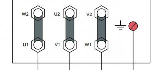
Operating principle of a single-phase asynchronous machine
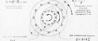
The operation of an asynchronous motor is based on the interaction of the rotating magnetic field of the stator and the currents induced by it in the motor rotor. When the rotation frequency of the pulsating magnetic fields differs, a torque occurs. It is this principle that is followed when regulating the rotation speed of an asynchronous motor using a frequency converter.
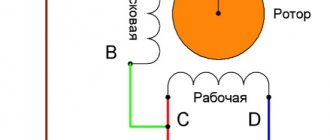
The electric motor can in fact be considered two-phase, but it has only one working stator winding, the second, located relative to the main one at an angle of 90°, is the starting one.
The starting winding occupies 1/3 of the slots in the stator structure, and the main winding accounts for 23 stator slots.
The rotor of a single-phase motor, short-circuited, placed in a stationary magnetic field of the stator, begins to rotate.
Fig. No. 1 Schematic drawing of a motor, demonstrating the principle of operation of a single-phase asynchronous motor.
The principle of operation of blood pressure
To understand why a starting winding is needed, let’s look at an example: the motor is connected only to the working winding (220V).
In it, I1 (single-phase current) creates a pulsating magnetic field. It can be decomposed into two - with the same amplitude and rotation speeds, but oppositely directed - Fa and Fv. When the rotor is stationary, these fields create torques M1 and M2 that are different in sign, but equal in magnitude.
The resulting starting torque is zero (Mn= M1 – M2), i.e. the motor will not be able to rotate without applying a load to the shaft.
Therefore, a starting winding is required. The field it creates causes the motor to rotate. The direction of rotation determines the starting initial torque.
Rotation speed control of single-phase motors
There are several ways to regulate the rotation speed of a single-phase motor.
- Controlling motor slip or voltage variation. The method is relevant for units with a fan load; it is recommended to use motors with increased power. The disadvantage of this method is heating of the motor windings.
- Step control of engine rotation speed using an autotransformer.
Fig. No. 2. Adjustment circuit using an autotransformer.
The advantages of the circuit are that the output voltage has a pure sinusoid. The transformer's ability to withstand overloads has a large power reserve.
Disadvantages - the autotransformer has large overall dimensions.
Using a thyristor engine speed controller. Thyristor switches connected back-to-back are used.
Rice. No. 3. Scheme of thyristor control of a single-phase asynchronous electric motor.
When used to regulate the rotation speed of single-phase asynchronous motors, the circuit is modified to avoid the negative influence of the induction load. LRC circuits are added to protect the power switches, a capacitor is used to correct the voltage wave, the minimum engine power is limited, this ensures that the engine starts. The thyristor must have a current higher than the motor current.
Transistor voltage regulator
The circuit uses pulse-width modulation (PWM) using an output stage built using field-effect or bipolar IGBT transistors.
Rice. No. 4. Scheme of using PWM to regulate a single-phase asynchronous electric motor.
Frequency regulation of a single-phase asynchronous electric motor is considered the main way to regulate the motor frequency, power, utilization efficiency, speed and energy saving indicators.
Rice. No. 5. Electric motor control circuit without excluding the capacitor from the design.
Motor speed control range when using a frequency converter
3.1 Using an inverter to reduce motor speed
To operate at low frequencies (below 10-15 Hz), special attention must be paid to motor cooling and shaft torque.
Enclosed fan cooled motor ( TEFC)
) has cooling only due to the built-in fan. The performance of the cooling fan decreases in proportion to the engine speed. When engine speed is reduced, cooling efficiency decreases, which leads to engine overheating and possible failure.
There are several options for cooling the electric motor when operating at low frequencies:
- reduce the period of continuous operation of the engine at low frequency
- organize additional cooling;
- reduce the load on the motor shaft;
- install a reduction gearbox, which will increase engine speed;
- use a larger motor.
The volt-frequency control method allows you to maintain a constant torque on the motor shaft at different speeds. When operating at low frequencies (below 5-10 Hz), the torque on the shaft will depend on the characteristics of the specific motor (active resistance of the windings). To maintain torque at frequencies below 5-10 Hz, it may be necessary to adjust the minimum voltage of the U/f
. Increasing the voltage value will cause an increase in starting torque, but will also lead to an increase in current consumption, and in proportion to the increase in flowing current, heating increases. Recommended frequency control range for voltage-frequency control: 5-50 Hz. The ELHART EMD-MINI frequency converter supports frequency adjustment from 0.5 to 999.9 Hz.
The vector control method is able to more accurately maintain torque at low frequencies (especially with changing loads). The range of possible adjustment is wider than that of the volt-frequency mode and depends on the specific model (company, series) of the inverter. For vector control, it is recommended to use Delta Electronics frequency converters of the VFD-E and VFD-C series.
To increase the starting torque, it is recommended to use a frequency converter of higher power (since the converter can only provide the motor with one and a half times the current (rated current × overload capacity of the inverter).
Frequency converter: types, principle of operation, connection diagrams
The frequency converter allows its owner to reduce energy consumption and automate processes in equipment and production management.
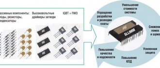
The main components of the frequency converter: rectifier, capacitor, IGBT transistors assembled into an output stage.
Thanks to the ability to control the parameters of the output frequency and voltage, a good energy-saving effect is achieved. Energy saving is expressed in the following:
- The engine maintains a constant current torque of the shaft. This is due to the interaction of the output frequency of the inverter converter with the engine speed and, accordingly, the dependence of voltage and torque on the engine shaft. This means that the converter makes it possible to automatically regulate the output voltage when it detects a voltage value that exceeds the norm with a certain operating frequency necessary to maintain the required torque. All inverter converters with vector control have the function of maintaining constant torque on the shaft.
- The frequency converter is used to regulate the operation of pumping units (see page). When receiving a signal from a pressure sensor, the frequency generator reduces the performance of the pumping unit. As the engine speed decreases, the output voltage consumption decreases. Thus, standard water consumption by a pump requires 50Hz industrial frequency and 400V voltage. Using the power formula, you can calculate the ratio of power consumption.
By reducing the frequency to 40Hz, the voltage is reduced to 250V, which means that the number of pump revolutions is reduced and energy consumption is reduced by 2.56 times.
Rice. No. 6. Using a Speedrive frequency converter to regulate pumping units using the CKEA MULTI 35 system.
To increase the energy efficiency of using a frequency converter in electric motor control, you must do the following:
- The frequency converter must match the parameters of the electric motor.
- The frequency generator is selected in accordance with the type of working equipment for which it is intended. Thus, the frequency converter for pumps operates in accordance with the parameters included in the program to control the operation of the pump.
- Precise settings of control parameters in manual and automatic mode.
- The frequency converter allows the use of energy saving mode.
- Vector control mode allows automatic adjustment of engine control.
Single-phase frequency converter based on EG8010 with PFC and pure sine.
I would like to introduce you to the next stage in the development of the frequency converter.
Brief background: I needed to somehow regulate the rotation speed of a single-phase asynchronous motor (duct (exhaust) fan), for which the only adequate solution is a frequency converter, and, not finding suitable options, I began developing it on the Arduino platform, which turned out to be extremely exciting, useful and not as simple as it initially seemed. However, after some time, the result was still obtained, although not exactly the one we would like, but still it worked and fulfilled the assigned tasks. This was written about in detail in my previous article. The main drawback of my frequency generator was the shape of the output voltage (far from sine, more like a parabola). And just at this time I came across information about the Chinese EG8010 microcircuit (and the board assembled on its basis EGS002) on the basis of which it was decided to assemble the next version of the frequency converter.
So, the main task is still the same: to obtain an alternating voltage of a sinusoidal shape at the output with the ability to regulate its frequency and amplitude. The EGS002 module is a bridge controller for a single-phase frequency converter with all the necessary protections and feedback. At the output, such a converter, depending on the configuration, can produce a sinusoid from 0 to 400 Hz, with a constant amplitude or an amplitude varying proportionally to the frequency. The carrier frequency of sine cutting is 23 kHz. It can also work in unipolar and bipolar modes (we don’t use the second one, so we won’t talk about it). In addition, it is possible to connect a display, a fan, an external temperature sensor (to control the fan) and even connect via the RS2323 port. For power supply, the module requires +5V for the processor and switch driver logic (IR2113) and +12V (+15V) to control the gates of these same switches. Well, of course, the voltage from which the sine wave is formed (from 12V to 400V), in my case +340V.
The documentation for the board contains errors in the very first diagram, both in English and in Russian, be careful:
Wrong:
Right:
Initially, I tried to supply rectified mains voltage as high voltage. And the first test version of the board was just with an input filter and a diode rectifier. However, as it turned out during the experiments, this voltage is not enough (depending on the network voltage +300V, maximum +310V), at the inverter output it was possible to get a maximum of 180-190 volts, which did not allow the fan to start at maximum speed, and besides at low voltage, voltage reduction does not work when the frequency decreases, which is unacceptable for an asynchronous motor.
There was a need to increase the input voltage. As it turned out, to obtain 220V output, with a margin for stabilization, it is necessary to supply at least +340V. The most obvious way to solve this problem is to use a power factor correction or PFC circuit. After studying the microcircuits that were in local stores, it was decided to assemble PFC on the ICE2PCS01G chip. This controller operates in continuous conduction mode (CCM), if I’m not mistaken, in Russian it will be in the “continuous current” mode, which gives such advantages as a low level of interference into the supply network and small losses in the inductor. Also, this microcircuit allows you to adjust the main PWM frequency and has a minimum number of elements in the harness. General aspects of working with the microcircuit are described in the datasheet, and the calculation of the values of the trim elements for specific parameters is carried out in the online calculator on the manufacturer’s website https://www.infineon.com/ (the calculator becomes available after registration). The ratings of the elements correspond to the circuit with the exception of the PFC choke; the best results were shown by a choke from a computer power supply with an inductance of 0.6-0.7 mH, this is slightly less than the calculated value (1.5 mH). The controller is powered by an external power supply voltage of +15V. After assembly, the only thing left is to set the output voltage to +340V using trimming resistor R15. A snubber chain (R29, C20) is desirable, but not required; with such a small load everything works fine without it. It is advisable to select a rectifier input diode bridge with a reverse voltage of at least 1000V, taking into account emissions at the inductor.
PFC module diagram:
Next about the power part, the inverter itself. The circuit is also taken from the datasheet on the EG8010, there is nothing special to tell here, the only difference is the diodes (D1, D6, D7, D8), they bypass the internal slow diode of the transistors, protecting the latter from high-voltage emissions of the windings of the connected motor, SF38 diodes are suitable for this, HER38 and the like. The power transistors in the datasheet are indicated as IRF840, but I used 9N90 in an insulated case, I think that it is undesirable to use less than 900V. The output choke, as many who have used this board advise, is best wound on rings of the MP-140 brand; I used a pair of semicircular rings measuring 24x13x7mm, thereby obtaining a core with dimensions of 24x13x14mm, respectively. The inductance for this inductor according to the datasheet is 3.3 mH, but in my case with such inductance the inductor got very hot, and the best results were obtained with an inductance of about 6 - 7 mH, wound with a wire of 0.4 mm * 2 wires, the estimated wire length is about 6 .5 m.
Power section diagram:
Nutrition. I didn’t reinvent the wheel, but simply left space on the board for a separate AC-DC converter with dimensions up to 60mm * 28mm, fortunately the same Chinese have a lot of them, for every taste (in my case, the diode bridge and high-voltage electrolyte were removed from the converter, because it already receives rectified mains voltage). It is best to use a source with an output voltage of 15V (for reliable opening of power switches), this voltage is supplied to the IR2113 drivers (located on the EGS002 module), and it also powers the PFC controller (ICE2PCS01G), then the voltage is first reduced by the LM7812 converter to 12V to power the fan , and after LM7805 up to 5 volts, respectively, which are already used to power the EG8010 itself and to power the driver logic.
A little about the modification of the EGS002 board. As I already wrote, it has several options for operation, by default the board is configured for use in an inverter and the jumpers are sealed in such a way that the output should be exactly 50Hz, however, this does not suit us.
In this case, you need VVVF mode (Variable Voltage and Variable Frequency Mode), a mode with variable frequency and variable voltage in the frequency range from 0 to 100 Hz.
To do this, it is necessary that there be a high level on pin 18, a low level on pin 19, and a high level on pin 32, to allow the voltage to change when the frequency changes. You don’t need to do anything with leg 19; it’s already sitting on the ground, but 18 and 32 need to be carefully unsoldered from the board, lifted so that they don’t touch the contact pads and pull them up to +5V, it seems to me that the easiest way to do this is by connecting them to the VCC power pin (26 leg), it should look something like this:
In addition to this, it is also necessary to unsolder the 16th leg, lift it from the board and make a tap from it; a potentiometer will be connected there to adjust the frequency. The remaining jumpers can be left untouched and left at default; they are responsible for the settings of both soft start and deadtime. Jumper JP9 turns on the display backlight, it can be soldered at will, I connected a button there without locking.
Frequency adjustment is carried out by changing the voltage on pin 16 (FRQADJ) using a 10 kOhm potentiometer, the outermost contacts of which are connected to +5V and ground, and the 16th leg and a capacitor to ground are connected to the slider to compensate for interference. However, this connection scheme has some nuances; the frequency is adjustable in the range from 0 to 100 Hz, which is redundant for the intended purpose.
Let me remind you that the amplitude (effective voltage value) also changes along with the frequency; initially, at the first start, the frequency value is set to 50 hertz and using the PR1 potentiometer, the output voltage is adjusted to 220-230 volts. Now and further, when adjusting the frequency, the voltage/frequency ratio will remain constant, therefore, as the frequency increases, the voltage will also increase, but with a +340V supply, the maximum that can be obtained is approximately 230V alternating voltage at the output, i.e. the frequency will increase, but the voltage will remain the same. In practice, it looks like this: the engine picks up speed up to 50 hertz, and with a further increase in frequency, the rotation speed begins to decrease, the engine does not have enough voltage, the rotor begins to lag further behind the rotation speed of the magnetic flux, in such cases they say: the engine slip increases, the torque decreases , heating losses increase, in general, this is not good for the engine. A similar situation is observed with an excessive decrease in frequency. To avoid these problems, it is necessary to limit the range of voltage adjustment on pin 16 and, accordingly, the frequency. This can be done by adding a resistor in series with the potentiometer on both sides:
During the tests, this option turned out to be optimal: a 10 kOhm resistor on the +5V side, 4 kOhm on the ground side. As a result, this manipulation limits the frequency adjustment from 17 Hz to 58 Hz, and as a bonus, smoother adjustment. The elements are soldered by surface mounting directly onto the potentiometer terminals. 10 kOhm multi-turn potentiometer.
Further technical aspects and tests. During initial tests there was almost no heating, neither on the power switches nor on the switch and PFC diode. Therefore, I didn’t bother with the radiator, I took an aluminum corner 20mm * 10mm * 2mm and made one common radiator from it. There was no need to isolate anything from him, because... all transistors and diode are in insulated housings. The only thing that heats up in this circuit is the output choke, and then up to a maximum of 48 degrees after an hour of operation at an ambient temperature of +26. Therefore, the holes in the case are sufficient for cooling. However, there is a connector for connecting a fan, as well as space in the case at the top (a small fan 10 mm thick will fit exactly). The airflow turns on at approximately 40 degrees (the temperature sensor is a 10 kOhm NTC thermistor R17).
A little about assembly and inclusion, if anyone suddenly decides to repeat it. I recommend not soldering the EGS002 module at first, plug it into the network and use trimming resistor R15 to set the voltage at the PFC output to 340 volts, then, having already soldered the module and setting the frequency on it to 50 Hz, use trimming resistor PR1 to set the output voltage to 220-230 volts.
The entire structure was originally designed for a Gainta G1037B case with dimensions of 189mm*113mm*66.6mm, a board with dimensions of 168mm*103mm, two-layer, ordered in China (only the test version was made with photoresist) all components are placed on one side, with the exception of the PFC controller, it was only in the SOIC-8 package therefore remained on the opposite side. The board in the pictures is slightly different from the finished one, because... Afterwards some points were corrected.
Board (picture) and photo of the assembly:
And a little bit of the debugging process and the first tests)
The project is open, created on the EasyEDA platform, located here: https://easyeda.com/Amatroskin/pfc-inv
That's all, thank you all for your attention. I welcome questions, comments, and constructive criticism.
Attached files:
- eg8010_datasheet_en.pdf (835 Kb)
- EGS002_manual_en.pdf (4290 Kb)
- Gerber_PFCINV.zip (261 Kb)
Tags:
- Voltage transformer
Single-phase frequency converter
The compact frequency conversion device is used to control single-phase electric motors for household equipment. Most frequency converters have the following design capabilities:
- Most models use the latest vector control technologies in their design.
- They provide improved torque for single-phase motors.
- Energy saving is set to automatic mode.
- Some models of frequency converters use a removable control panel.
- Built-in PLC controller (it is indispensable for creating data collection and transmission devices, for creating telemetry systems, and integrates devices with various protocols and communication interfaces into a common network).
- Built-in PID controller (monitors and regulates temperature, pressure and technological processes).
- The output voltage is adjusted automatically.
Fig. No. 7. Modern Optidrive converter with basic functional features.
Important: A single-phase frequency converter, powered by a single-phase network with a voltage of 220V, produces three linear voltages, the value of each of them is 220V. That is, the linear voltage between the 2 phases is directly dependent on the output voltage of the frequency converter itself.
The frequency converter does not serve for double voltage conversion; due to the presence of a PWM regulator in the design, it can increase the voltage value by no more than 10%.
The main task of a single-phase frequency converter is to provide power to both single- and three-phase electric motors. In this case, the motor current will correspond to the connection parameters from a three-phase network and remain constant
Purpose of the frequency converter
Asynchronous motors, in comparison with other electric machines, are more powerful and efficient, but have the disadvantage of the need to be equipped with additional elements responsible for the rotor rotation speed.
The same applies to the starting current, which is 5-7 times higher than the rated current, due to which shock loads lead to loss of energy and all together reduce its service life.
To combat these problems, there is a class of devices that automatically controls inrush currents. They are called frequency converters.
With their help, it is possible to reduce starting currents by 5 times, achieving a smooth start.
In addition, by adjusting frequencies with voltage, the rotor is controlled.
In addition to these advantages, the use of such devices has the following:
- at the time of start-up, up to 50% energy is saved;
- with their help, feedback is carried out between adjacent conductors. Their
- can be called three-phase voltage generators of the desired value and frequency.
Frequency regulation of single-phase asynchronous electric motors
The first thing we pay attention to when choosing a frequency converter for our equipment is the correspondence of the mains voltage and the rated value of the load current for which the motor is designed. The connection method is selected relative to the operating current.
The main thing in the connection diagram is the presence of a phase-shifting capacitor; it serves to shift the voltage supplied to the starting winding. It is used to start the engine, sometimes after the engine has started, the starting winding along with the capacitor is turned off, sometimes it remains on.
Selection of frequency converters
For manufacturers of these devices to win the market, price is important, as with any electronic equipment. To reduce it, they create devices with a minimal set of functions, i.e. The more expensive a frequency converter is, the more versatile the device is, which is important for a consumer who wants to extend the life of the engine.
We recommend:
- Do-it-yourself quadcopter assembly, step-by-step assembly
- Three-phase asynchronous electric motors, technical characteristics, types, features
- Connection diagrams for a three-phase electric motor for 220 volts
Winding connection methods
Engines in everyday life and in amateur practice drive a variety of mechanisms - a circular saw, an electric plane, a fan, a drilling machine, and pumping equipment. Without knowing how electric motors work, it is better not to get into the weeds with frequency drives. Engines are:
- permanent
- and alternating current (asynchronous and synchronous).
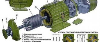
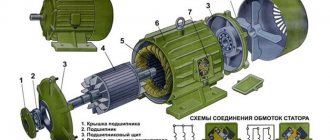
The mechanism includes a rotor and a stator. The principle of electromagnetic induction, studied in school, underlies the principle of their operation. Most of the electric motors produced are “asynchronous”. Where did this word come from? The rotation frequency of the moving part (rotor) always lags behind the rotation frequency of the magnetic field of the stationary part (stator). The output frequency scale varies - 1000, 1500, 3000... rpm. And all because the rotor is able to rotate on the shaft at different speeds inside the core.
Depending on the number of poles, the units are one-, two-, or three-pole. In the stator core of the latter there is a winding for each phase, the ends of which are brought out to the terminal box. How can you increase the speed of an asynchronous motor (IM) without losing power? By changing the number of pole pairs.
To move on to other methods, and there are two more of them, we cannot do without the symbols “star” and “triangle”. The three windings of the coil can be connected in two ways: at a point or in a circle, hence the names of the connections “star” and “triangle”.
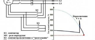
What happens if a three-phase motor connected by a triangle is connected to a 380 V power supply? In this case, the starting current values can increase seven times, which will lead to network overload. When dealing with engines, you need to be extremely careful. When buying a product, be sure to think about whether the nameplates show a triangle/star icon (and not vice versa star/triangle) at the same voltage of 220/380 V.
Single-phase frequency converter ESQ-A200
A small-sized single-phase frequency converter is needed to control an asynchronous motor with capacitor start (AIRE, ABE, etc.)
Such motors are installed in electric fans, washing machines, refrigerators, etc.
On the website https://xn--80aqahnfuib9b.xn--p1ai/esq_A200.html you can see all the characteristics of the device. Here you can buy it, having decided on the table with the model.
| Model | Current, A | power, kWt | Dimensions (HxWxD) | Weight, kg | Price, RUB including VAT |
| ESQ-A200 series, single-phase 1/1 phase, 200-260 V (for single-phase electric motors) | |||||
| Frequency converter ESQ-A200-2S0007 for single-phase motor 0.75 kW | 4,7 | 0,75 | 141x85x113 | 1,1 | 14 338 |
| Frequency converter ESQ-A200-2S0015 for single-phase motor 1.5 kW | 7,5 | 1,5 | 141x85x113 | 1,2 | 13 874 |
| Frequency converter ESQ-A200-2S0022 for single-phase motor 2.2 kW | 10 | 2,2 | 170x125x113 | 2 | 19 007 |