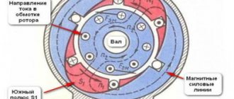
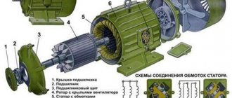
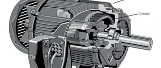
Three-phase asynchronous motors have found the widest application in industry and other fields. Modern equipment is simply impossible to imagine without these units. One of the most important components of the operating cycle of machines and mechanisms is their smooth start and the same smooth stop after completing the task. This mode is provided by using frequency converters. These devices have proven to be most effective in large, high-power electric motors.
With the help of frequency converters, inrush currents can be successfully adjusted, with the ability to control and limit their magnitude to the required values. To use this equipment correctly, you need to know the operating principle of a frequency converter for an asynchronous motor. Its use can significantly increase the service life of equipment and reduce energy losses. Electronic control, in addition to soft start, provides smooth adjustment of the drive in accordance with the established relationship between frequency and voltage.
What is a frequency converter
The main function of frequency converters is to smoothly regulate the rotation speed of asynchronous motors. For this purpose, a three-phase voltage with variable frequency is created at the output of the device.
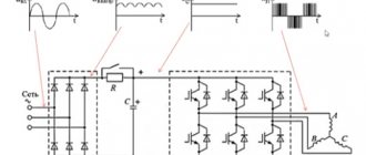
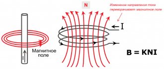
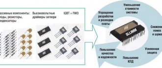
Frequency converters are often called inverters. Their basic principle of operation is to rectify the alternating voltage of an industrial network. For this purpose, rectifier diodes are used, combined into a common unit. Current filtering is carried out by high-capacitance capacitors, which reduce the ripple of the incoming voltage to a minimum. This is the answer to the question why a frequency converter is needed.
In some cases, the circuit may include a so-called energy drain circuit, consisting of a transistor and a resistor with high power dissipation. This circuit is used in braking mode to suppress the voltage generated by the electric motor. This prevents capacitors from overcharging and premature failure. As a result of the use of frequency drives, asynchronous motors are successfully replacing DC electric drives, which have serious disadvantages. Despite the ease of adjustment, they are considered unreliable and expensive to operate. During operation, the brushes constantly spark, and electrical erosion leads to wear on the commutator. DC motors are completely unsuitable for explosive and dusty environments.
Digital models of asynchronous motor
In Fig. Figure 2 shows a digital model of an IM controlled by stator currents, with one short-circuited frame on the rotor. The model was built in the Matlab 6.5 Simulink 5 system using the differential equations of an unsaturated IM obtained in article [6] (system of equations (13)):
where Mm is the maximum mutual inductance between the stator winding and the rotor frame; l and D are the length and diameter of the IM rotor; KB is the proportionality coefficient between the stator winding current and the magnetic induction on its axis in the air gap; J is the total moment of inertia of the motor and load; α is the rotor rotation angle.
Rice. 2. Digital model of an IM with one short-circuited loop on the rotor when controlling stator currents
Time diagrams of absolute slip (the difference between the synchronous rotation speed and the rotor speed) in rad/s, the rotor current ia in A and the difference between the electromagnetic torque and the load torque Mr – MN in N m with an abrupt application of MN to the IM, which is in the ideal idle mode stroke (Ω = ω), are presented in Fig. 3 and 4. Hypothetical blood pressure parameters: l = 0.6 m, D = 0.4 m, KB = 0.05 T/A, Mm/L = 20, r/L = 10p, ω = 100pc-1, Im = 10 A. The calculated value of the maximum constant component of the electromagnetic torque is Mrmax = 27 N m, J = 3.84p kgm2.
Rice. 3. Transient process when applying a braking torque of 1 N•m to the IM, which is in ideal idle mode
In Fig. 3 and 4 show processes at MN = 1 and 0.5 N m, respectively. Their analysis shows that with one frame on the rotor in a steady state, the frequency of oscillations of the load torque and absolute slip, and therefore the rotor rotation frequency, is twice as high as the frequency of the non-sinusoidal rotor current.
Rice. 4. Transient process when applying a braking torque of 0.5 N•m to the IM, which is in ideal idle mode
With a large number of rotor rods, the digital model of the IM turns out to be very cumbersome. To simplify it, it is desirable to decompose the system of differential equations that describes it. The result obtained in article [6] for the steady state under the main control method, defined by the expressions:
and an arbitrary number of rods 2N of the “squirrel cage” rotor suggests that decomposition of the system of electromagnetic equilibrium equations is possible, equation (27')]:
where Mkj = Lcos((k – j)δ) is the mutual inductance between the rotor frames, k, j = k ≠ j, δ = π/N.
Let us assume that the system of equations (3) admits decomposition to the form:
The solution to the system of differential equations (4) in the form of the Laplace transform has the form:
Where
To confirm the validity of the decomposition of system (3), it is proven that solution (5) of system (4) is also a solution to system (3).
The possibility of decomposition significantly simplifies the construction of a digital model of IM, which is too cumbersome for large values of N.
In Fig. For simplicity, Fig. 5 presents a digital model of an IM controlled by stator currents with three frames on the rotor (2N = 6).
Rice. 5. Digital model of an IM controlled by stator currents, with three frames on the rotor (2N = 6)
The model was built in Matlab 6.5 Simulink 5 using the system of equations obtained in article [6]:
In Fig. Figure 6 shows the process of testing the system for regulating the rotation speed of the IM (Fig. 1) of a stepwise changing set value of the rotation speed (ΩЗ = 20π1(t) – 10π1(t – 7)) rad/s at a load torque МН = 0. After jumps ΩЗ due to the constant frequency of rotor currents (absolute slip) v = ΩЗ – Ω, corresponding to the extremum of the electromagnetic torque of the motor, the process of changing the frequency of rotation of the motor Ω occurs with the maximum possible with a given limitation of the amplitude of the stator currents by the electromagnetic torque of the motor Mr.
Rice. 6. The process of working out a stepwise changing set value of the rotation speed at MN = 0
For simplicity of the model, the number of frames on the rotor is assumed to be 3. The amplitude of the stator currents is limited to the value Inmax = 20 √2 A. The remaining hypothetical parameters of the IM are left unchanged. The calculated values of the Mr extremum are Mrе= 216 N·m. The proportional regulator of the specified stator current amplitude has a value of K = 20 As/rad.
Note that after a jump in the driving influence, the process of increasing Mr occurs in the model with an abrupt change in the stator currents, which is not physically realizable.
In Fig. Figure 7 shows the process with the same input action ΩЗ and MH = 40 Nm. In steady state conditions, the control error depends on the load torque and is ∆Ω = 0.607 rad/s. Increasing Kv by five times to K = 100 Ac/rad makes it possible to reduce ∆Ω also by five times. Using a PI controller instead of a P controller allows you to reduce ∆Ω to zero.
Rice. 7. The process of working out a stepwise changing set value of the rotation speed at MH = 40 N•m
Operating principle of the frequency converter
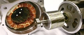
Efficient and high-quality control of asynchronous electric motors has become possible through the use of frequency converters together with them. The overall design is a variable frequency drive, which has significantly improved the technical characteristics of machines and mechanisms.
The control element of this system is a frequency converter, the main function of which is to change the frequency of the supply voltage. Its design is made in the form of a static electronic unit, and the generation of an alternating voltage with a given variable frequency is carried out at the output terminals. Thus, by changing the voltage amplitude and frequency, the rotation speed of the electric motor is adjusted.
Asynchronous motors are controlled in two ways:
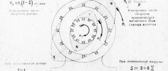
- Scalar control operates in accordance with a linear law, according to which amplitude and frequency are proportionally related to each other. The changing frequency leads to changes in the amplitude of the incoming voltage, affecting the torque level, efficiency and power factor of the unit. The dependence of the output frequency and supply voltage on the load torque on the motor shaft should be taken into account. In order for the load torque to be always uniform, the ratio of the voltage amplitude to the output frequency must be constant. This balance is precisely maintained by the frequency converter.
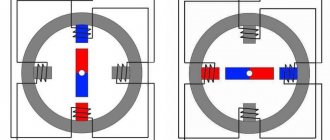
- Vector control keeps the load torque constant throughout the entire range of frequency adjustments. Control accuracy increases and the electric drive responds more flexibly to changing output loads. As a result, the motor torque is directly controlled by the converter. It must be taken into account that the torque is formed depending on the stator current, or more precisely, on the magnetic field it creates. Under vector control, the phase of the stator current changes. This phase is the current vector that directly controls the torque.
Introduction
When regulating the stator currents of a motor controlled from an autonomous inverter, covered by negative feedback on the stator phase currents [1, 2], the difference between the stator winding currents and the specified values can be neglected. This makes it possible to significantly reduce the inertia of the motor associated with the inductance of the stator windings, and with sufficiently smooth changes in the specified frequency and amplitude of the stator currents, consider a three-phase controlled alternating current generator, which regulates the instantaneous values of the stator currents, as the IM power source. In this case, the control actions for the IM are the stator currents. Thus, it is possible to use a simpler control algorithm that creates in a closed-speed electric drive the maximum acceleration during acceleration and deceleration, as well as the minimum stator currents that provide the necessary electromagnetic torque of the IM in steady state, in comparison with the known vector and scalar methods of IM control [3–5].
Setting up a frequency converter for an electric motor
In order for the frequency converter for an asynchronous motor to fully perform its functions, it must be correctly connected and configured. At the very beginning of the network connection, a circuit breaker is placed in front of the device. Its rating must match the amount of current consumed by the motor. If the frequency generator is intended to be operated in a three-phase network, then the machine must also be three-phase, with a common lever. In this case, if there is a short circuit in one of the phases, you can quickly turn off the other phases.
The actuation current must have characteristics that fully correspond to the current of an individual phase of the electric motor. If the frequency converter is planned to be used in a single-phase network, in this case it is recommended to use a single circuit breaker, the rating of which should be three times the current of one phase. Regardless of the number of phases, when installing a frequency switch, the machines should not be connected to a break in the ground or neutral wire. It is recommended to use direct connection only.
If the frequency converter is correctly configured and connected, its phase wires must be connected to the corresponding contacts of the electric motor. The pre-windings in the motor are connected in a star or delta configuration, depending on the voltage supplied by the converter. If it matches the smaller value indicated on the motor housing, then a delta connection is used. At higher values, a star circuit is used.
Next, the frequency converter is connected to the controller and control panel, which is included in the delivery package. All connections are made in accordance with the diagram given in the instruction manual. The handle must be in the neutral position, after which the machine turns on. Normal activation is confirmed by an indicator light on the remote control. In order for the converter to work, the RUN button, programmed by default, is pressed.
conclusions
Asynchronous electric motors are superior to DC motors in many respects. This superiority concerns both the device and reliability. Therefore, in many cases, users choose asynchronous motors, guided precisely by considerations of their superiority over other devices.
Mechanical current control causes some negative consequences, since when using this control option one cannot be sure of one hundred percent and high-quality operation of the equipment. The use of frequency converters for asynchronous motors has its very important advantages, which are important in many aspects of working with motors. One of the most important advantages of using electronic control and frequency converters is the fact that these devices allow you to save energy consumption. In addition, the power will be greater.
Frequency drivers should be selected taking into account many characteristics that are specified in the documentation attached to the device. Home-made frequency converters can be useful in domestic conditions, but they should not be used in production.
The operation of converters must be carried out correctly, in accordance with all recommendations and rules. This will improve the quality of equipment operation. In addition, many tips will extend the life of the engine and converter. It is highly recommended to monitor the voltage. In the event of a critical increase in voltage, capacitors may explode. Frequency generators must be used in compliance with all basic safety rules. It is recommended not to start working with them without all the necessary knowledge in this area.