Well pump kit
Let's look at the encountered (recommended) submersible well pump kit. Typically this kit includes:
- The pump itself. It is often sold separately;
- Electrical cable for connection. Included in the pump kit;
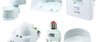
- Automation block. Sold as a set or as additional equipment;
- Hydraulic accumulator (expansion tank). Sold as additional equipment.
The given equipment for a well pump is the maximum and is not typical for all manufacturers of well pumps. The automation unit (control system) and hydraulic accumulator may not be included in the kit and their need is determined by the water supply scheme of the house. In the simplest version, the well pump is equipped only with an electrical cable for connection.
Understanding this, let's consider three options for connecting a well pump.
- Connecting a well pump to power supply without automation;
- Connecting the well pump to the power supply with the control unit (system) (automation unit);
- Connecting the well pump to the power supply via a pressure switch.
Harness
There are two types of heating systems - forced and natural circulation. Systems with forced circulation cannot work without a pump; systems with natural circulation work, but in this mode they have lower heat transfer. However, less heat is still much better than no heat at all, so in areas where electricity is often cut off, the system is designed as hydraulic (with natural circulation), and then a pump is installed into it. This gives high heating efficiency and reliability. It is clear that the installation of a circulation pump in these systems is different.
All heating systems with heated floors are forced - without a pump, the coolant will not pass through such large circuits
Forced circulation
Since a forced circulation heating system without a pump is inoperative, it is installed directly into the gap in the supply or return pipe (of your choice).
Most problems with the circulation pump arise due to the presence of mechanical impurities (sand, other abrasive particles) in the coolant. They can jam the impeller and stop the motor. Therefore, a mesh dirt filter must be placed in front of the unit.
Installing a circulation pump in a forced circulation system
It is also advisable to install ball valves on both sides. They will make it possible to replace or repair the device without draining the coolant from the system. Turn off the taps and remove the unit. Only that part of the water that was directly in this piece of the system is drained.
Natural circulation
The piping of the circulation pump in gravity systems has one significant difference - a bypass is required. This is a jumper that makes the system operational when the pump is not working. One ball shut-off valve is installed on the bypass, which is closed the entire time the pumping is running. In this mode, the system operates as forced.
Installation diagram of a circulation pump in a system with natural circulation
When the electricity goes out or the unit fails, the valve on the jumper is opened, the valve leading to the pump is closed, and the system operates as a gravity system.
Installation features
There is one important point, without which the installation of the circulation pump will require rework: it is necessary to rotate the rotor so that it is directed horizontally. The second point is the direction of flow. There is an arrow on the body indicating which direction the coolant should flow. This is how you turn the unit so that the direction of movement of the coolant is “in the direction of the arrow”.
The pump itself can be installed both horizontally and vertically, just when selecting a model, make sure that it can work in both positions. And one more thing: with a vertical arrangement, the power (pressure created) drops by about 30%. This must be taken into account when choosing a model.
Connecting a well pump without auxiliary equipment
Without a control unit, automation unit or other auxiliary equipment, the pump's power supply cable is connected to a pre-installed electrical outlet with a grounding contact.
Grounding of a borehole (submersible) pump is mandatory. To directly connect the grounding, the GZSh (main grounding bus) of the house is used, which in turn is connected to the existing grounding loop of the house.
An electrical cable with a grounding conductor is used to supply power to the pump socket. The supply voltage of the submersible pump is 220 volts.
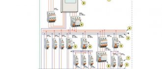
To power the pump, you need to select a separate electrical group and protect this group with a circuit breaker. The rating of the circuit breaker is calculated based on the electrical power of the pump. So for pumps up to 3,000 W you need a 10 Ampere circuit breaker, for pumps of higher power you will need a 16 Ampere circuit breaker.
Important! This connection cannot be considered correct. It only shows the general principle of connecting a well pump. The lack of automation in controlling the operation of the pump will lead to its malfunctions when water disappears (dry running) in the supply system.
Where to put
It is recommended to install a circulation pump after the boiler, before the first branch, but on the supply or return pipeline it doesn’t matter. Modern units are made from materials that can withstand temperatures up to 100-115°C. There are few heating systems that work with a hotter coolant, so considerations of a more “comfortable” temperature are untenable, but if you feel safer, put it in the return line.
Can be installed in the return or direct pipeline after/before the boiler up to the first branch
There is no difference in hydraulics - the boiler, and the rest of the system; it makes absolutely no difference whether there is a pump in the supply or return branch. What matters is the correct installation, in the sense of strapping, and the correct orientation of the rotor in space. Nothing else matters.
There is one important point regarding the installation location. If the heating system has two separate branches - on the right and left wings of the house or on the first and second floor - it makes sense to install a separate unit on each, and not one common one - directly after the boiler. Moreover, the same rule remains on these branches: immediately after the boiler, before the first branch in this heating circuit. This will make it possible to set the required thermal conditions in each part of the house independently of the other, and also in two-story houses to save on heating. How? Due to the fact that the second floor is usually much warmer than the first floor and much less heat is required there. If there are two pumps in the branch that goes up, the speed of movement of the coolant is set much lower, and this allows you to burn less fuel, without compromising the comfort of living.
Connecting a well pump to power supply with a control unit (automation unit)
Direct connection of the pump is fraught with rapid failure of the pump. The main cause of the malfunction is the pump running idle when the water level drops.
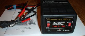
For simple water supply systems, the best option is to include ready-made (factory) automation units in the water supply scheme (example in the photo). Sometimes such units are called deep-well pump control stations. Sometimes with a hydraulic controller. They are needed:
- For smooth start and smooth stop of the pump;
- For automatic pressure maintenance;
- Protection of the pump from “dry pumping”, without water;
- Protection of the pump from power surges;
- Protection against lack of water intake;
- Network overload protection.
Block models are different and the set of listed functions may change. An automatic control unit for a well pump is a necessary device, and that is why reputable companies include it in the pump package, often with limited functionality.
The automation unit (hydraulic controller) is quite compact in appearance. The connection is also simple, and a simple electrical circuit of a well pump with a control unit can be represented as follows.
However, for longer operation of the automation unit, it is better to consider the diagram of its connection through a contactor. The controller will ensure simultaneous activation of the automation unit with the submersible pump.
How to connect a pump to a well and water supply
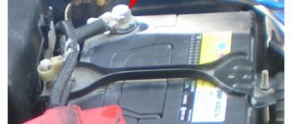
Before installing a submersible pump, thorough cleaning of the well shaft is required. For this purpose, using a temporary pump, liquid is pumped out of the column until all sand and impurities are removed. To protect the pressure device from water hammer, you need to install a non-return valve on it.
The pump is connected to the well in the following sequence:
- The pipeline is being installed. When connecting the pump to a rigid pipe between it and the main line that transfers water to the consumer, it is better to insert a small piece of flexible hose to dampen the vibration of the electric motor.
- A cable, electrical wire, or hose are connected to the device.
- The device is smoothly lowered into the well.
- When the pump reaches the bottom, it is raised half a meter to a meter.
- The cable is rigidly fixed, the cable is connected to the electrical network, the hose is connected to the rest of the system and laid in the mounting channels.
A cover should be installed at the wellhead to prevent dirt and foreign objects from entering the shaft.
Connecting the well pump to power supply via a pressure switch
To reduce the cost of the pump kit, you can connect the pump without a control unit, using only a pressure switch.
The pressure switch ensures that the pump is disconnected from the power supply when the water pressure in the system reaches the upper limit and the pump is turned on when the water pressure reaches the lower limit. When working in a water supply circuit with an expansion tank (hydraulic accumulator), pressure thresholds are measured in the tank.
Connection diagram
Length of water pipeline and number of nodes
Although water will move horizontally through the system, losses in nodes and pipes cannot be avoided. It is recommended to purchase purchased equipment with a power reserve of up to 20%.
These devices are also divided into two categories:
- centrifugal , which have a higher price and better performance;
- vibration ones , which cost less and work worse.
Vibration pumps have a suction valve, which can be located:
- at the top of the device;
- at the bottom of the device.
The ability to avoid the ingress of bottom dirt, in the first option, can be compensated by the problem of working with a low water level in the well.
The second option has downsides - such a pump sucks up clay near the bottom, while the low water level will become much less of an obstacle.
The installation of vibration devices is not recommended in sand wells, which are generally considered to be all channels drilled to the depth of interstratal or groundwater.
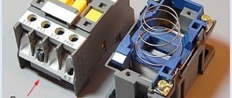
Mixed connection diagram of the automation unit and pressure switch
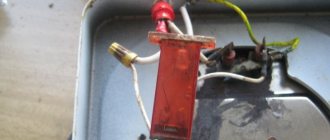
The automation unit protects the pump from running dry (lack of water). This is sometimes not enough. To protect against low water pressure, a pressure switch, for example RD5, is installed in the circuit. Its device is shown in the figure.
The pressure relay and automation unit are included in the circuit like this.
Installation features for other water supply systems
Even after reading the recommendations on how to properly install a surface self-priming pump in a well or well, difficulties may arise when connecting the equipment to other sources. These tips will be useful for those who are planning to automate the supply of water from a water column or storage barrel.
It’s not too late to think about how to connect a surface pump to a column, even after installing a hand pump. It is recommended not to dismantle the manual control, but to supplement it with automation.
For both devices to work, you need to cut under the check valve of the column, install a tee with a check valve and connect the electric pump through a rigid pipe. It is better to replace the check valve on the column or install another one on the tee to prevent air from being sucked in from the side of the column. A ball valve is inserted between the hand pump and the pipe.
The principle of operation of the combined column is simple: first, the column is raised above the ball valve using a hand pump, then it is closed and the electric pump is started
It is important that there is always water in the “glass” of the column; if necessary, it must be added
Irrigation barrels come in handy in dachas and suburban areas, and using a pump greatly simplifies the difficult work of a gardener. The electric pump not only automatically supplies water, but also creates the necessary pressure. On sale it is easy to find inexpensive, simplified equipment for barrels and advanced automatic garden models that work with micro-drip irrigation systems.
Before connecting the surface pump to the barrel, it is necessary to connect hoses for water intake and irrigation to the device. Rubber hoses are not suitable for this purpose - they will simply shrink from water pressure and will not be able to perform their task. The device is installed on the ground, as close to the container as possible. Only hoses are lowered into the water - the body of the device must remain out of reach of splashes. After completion, the pump is stored in a dry place.
Compact barrel models were invented especially for summer residents - they are installed on the edge of a container with water. These convenient devices are equipped with filters and pressure regulators. The kit almost always includes hoses.
Connection diagram for pressure switch RD5 and protection LP/3
You can simplify the circuit, otherwise reduce its cost, without losing installation quality, by installing an LP/3 protection relay instead of the automation unit. The main disadvantage of this scheme is the need to manually start the pump after shutdown, which is compensated by its low cost.
Pay special attention to connecting RD5 and LP/3 in a single circuit. They are connected in series, that is, when the pressure drops and when running dry (lack of water), the pump turns off. Again, in this scheme the pump is restarted manually.
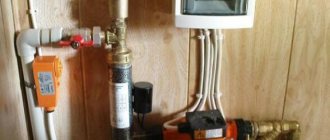
Installation process
The installation process of a simple automated system, which will include a pressure switch, does not require special knowledge or much effort. The first step is to assemble the pump unit and install it in the well. In parallel with it, a power cable is lowered, which is tied to the supply pipe. On the surface, the pipe that comes from the pump is connected to the accumulator. To do this correctly, you need to prepare the accumulator. In order for the latter to perform its function, it must contain air under pressure. The pressure value should be slightly higher than the lower shutdown threshold. This gap is 10%.
To pump in the required amount of air, you need to unscrew the special cap at the back that covers the spool. To work, you will need a car pump with a pressure gauge or a regular hand pump without it. If the pressure does not rise, then the problem may be with the rubber bulb that is located inside the tank. After preparing the tank, a brass five-piece adapter is installed on it. An automatic device is screwed into one of its holes, and a pressure gauge is screwed into the second. These holes are smaller in diameter than others. A pipe is supplied to one of the large holes, which comes from the pump, and to the other - a pipe that will go to consumers.
Next comes the connection of the electrical part of the automation. The terminals are designated by three Latin letters, which indicate which wire is connected where. The neutral wire is supplied to the hole with the letter N, the phase wire is supplied to the hole L, the third hole can be indicated by an icon with three stripes or the letter E, the ground wire must be connected to it. The power cable is not connected directly to the general meter circuit breaker. A separate machine must be installed for it. It is desirable if it is differential in order to catch the slightest leaks due to moisture getting inside the automation.
After connecting the cables, do not rush to close the automation cover; you will need to adjust the operating pressures. The large spring, which is located inside the automatic pump, is designed to adjust two values at once. The spread between these values is controlled by a smaller spring, also called delta. You will need to test run the pump. As soon as the pressure reaches a critical point and it turns off, you need to monitor the pressure gauge and note the point at which the engine turns on. The standard value that many choose for themselves is from 1.5 to 2 atmospheres.
If the pressure gauge shows that the readings are higher, then on the automatic pump you need to turn the nut of the large spring clockwise. Don't be too zealous, because one turn can change the value by 0.8 atmospheres. When the desired value for the water pressure from the pump is reached, then you can set the upper point in a similar way, but you should rotate not a large, but a small spring. A video of setting up the automation for the pump can be seen below.
Conclusion
The presented electrical diagrams for connecting a well pump are the simplest, but most common in the private sector for home water supply. However, it is worth noting that for large houses and powerful pumps, more complex automation and startup schemes for water supply pumps are used.
©Elesant.ru
More articles
- Do-it-yourself water drilling for water supply to a house, cottage, or dacha
- Types and choice of surface pump for a private house
- Choosing polyethylene pipes for external water supply at home
- Choosing a water supply scheme for your home: do-it-yourself water supply for your home
- Choosing a well pump is easy
- Sources of water supply systems for a private home
- How to install a well for a private house
- External and internal water supply of a country house
- Water supply to the house: external water supply of a private house
- Laying a trench for the external water supply of a private house
- Calculation of a surface pump: how to calculate the pressure of a surface pump
- Calculation of a well pump: formula and example of detailed calculation
- Private house water supply systems
- Automatic water supply station: selection and installation of a water supply station
- Insulation of the external water supply of a house: materials and methods of insulation
Installation location
Usually the pumping station is assembled in a heated room. The ideal place would be a boiler room with well-equipped sound insulation. There are other options for installing a water supply station. Often it is placed in the basement or basement, but subject to their heat, sound and waterproofing. You can also use a special box - it is placed in the underground with a hatch providing access to the equipment.
A platform is used to place the station in the well. It is installed below the freezing level of the ground. In this case, the structure of the well should be insulated from above. But this method of placing a water station is characterized by problematic access to it.
You can also provide space in the caisson for the pumping station. To do this, a structure is built around the well, buried below the freezing level of the soil. The caisson is closed and thermally insulated at the surface of the earth. For maintenance, a small hatch will be sufficient.
You can also build a house for a pumping station or place equipment in an extension. If this is a separate building, it must not only be insulated, but also heated in cold weather.
Self-installation allows you to significantly reduce the cost of installing a pumping unit. Depending on the type of source, different connection schemes for the water station are used. Correct installation depends, among other things, on small elements such as an oil seal, check valve, filters, etc. They can improve and make the operation of pumping equipment longer.