Scope of application of circuit breakers and switches
From all of the above, it is clear that such devices are designed to switch circuits that under no circumstances should be connected to each other.
One striking example is switching an object to a backup source. Suppose you are tired of constant power outages in your country house and have acquired a gas generator. The electricians turned off the power, you switched to the generator. Turned it on - you are powering your house again from the standard network. Everything is simple in words, but how to do it practically? This is where a changeover switch will help you out. Take a look at the diagram below: In one switch position the house is connected to the mains, in the other it is connected to the generator. Moreover, even if there is voltage in both the network and the generator, switching does not threaten anything - it is impossible to connect the network to the generator. Unfortunately, although this scheme is simple, it is not entirely correct. Let's look at the actions you must take when connecting the generator:
- Disconnect the house from the standard electrical network.
- Start the generator and bring it into operating mode.
- Connect the house to the generator.
You don’t need to be a rocket scientist to understand that it is impossible to perform such a sequence of operations with a conventional changeover device. You will either have to start the generator first and then switch, or switch sources and then start the generator.
If the first option is still suitable, then the second is absolutely unacceptable for most household appliances. How will a refrigerator feel, for example, if during the startup of a gas generator the supply voltage begins to rise from 0 to 220 V, and the frequency from 0 to 50 Hz? If you don't know, it will burn.
Pass-through switches always work in pairs
Now take a look at the third option, which shows how pass-through switches should actually be used
Please note that there are two wires between the control points. And this is a big minus for those who hoped to somehow use old veins lying in the thickness of the walls for control.
Look, now you can see that the neutral (black wire) goes straight to the chandelier. But the neutral can be broken or connected at any time from both ends of the corridor. In this case, there is always a phase on one of the wires, and you just need to apply it to the desired point. Due to this, the whole problem is solved.
Now we leave the bedroom, turn on the light, get to the threshold of the kitchen, and turn off the chandelier. By the way, if someone wants to join night gatherings, they will solve their problems in exactly the same manner without any difficulty. But what if we need to place another switch - say - near the front door?
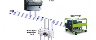
Distribution board diagram with a “network-generator” switch
Details Published: 04 June 2015
In dacha areas, garden plots, the private sector and similar places, frequent power outages are common. Here they can turn off the lights for an hour, for the whole day or for a longer time. This creates quite a few problems, since people can no longer imagine life without electricity. He has things working at home: a refrigerator, a TV, room lighting, a pump for watering the garden, and the like.
Gasoline power plants are very popular in such places. Turn off the lights, start the gas generator and continue to enjoy life. The power plant must be connected to the distribution board through a special outlet. Below I look at the diagram of a distribution board with a “mains-generator” switch, which allows you to switch to power supply from a gas generator when the external network is lost and back.
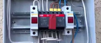
Here I am considering manual switching, which is carried out using a reversing switch. All diagrams show an ABB OT40F3C switch. This is a high-quality and reliable reversible switch. It has three positions:
- the handle is turned to the left - the contacts on its left side are closed, and on the right side they are open;
- the handle is in a vertical position - all contacts are open (both right and left);
- the handle is turned to the right - the contacts on its right side are closed, and on the left side they are open.
If what is written is not entirely clear, then look at the latest diagram and you will immediately understand how it works.
It is worth noting that if you take such a reversing switch for a higher current, then the switch handle is not included in the kit. It must be purchased separately.
Below is a simple single-phase switchboard diagram with a mains-generator switch. This is plenty for a small dacha or garden house. If you have a large house, then you need to revise the ratings of the input machine and increase the number of group lines. Everything is individual here.
It is very convenient to use a network indicator in such panels. For example, the signal lamp LS-47. Why is she needed here? Let's say the lights are turned off and you start the power plant. Everything is working.
Next, how to determine whether there is voltage in the network or not? You won’t run to the switchboard every half hour and use an indicator to check whether the light is on or not. This is not convenient and is forgotten over time. So you can miss this moment and “sit” on the gas generator until the evening. And gasoline is expensive these days.
In such a situation, the mains voltage indicator will immediately show you when the light comes on
It will just light up and you will immediately notice it. It is clearly visible from afar even through the transparent cover of the shield
As soon as the warning light came on, they immediately turned off the power plant and switched the switch to mains mode.
Below is the same diagram of the distribution board, but with an LS-47 signal lamp.
If you want to protect yourself and your dacha from current leaks, then you need to install an RCD. Below is a diagram with one common protective device. If you want more, then go ahead and fight. Here you can fantasize endlessly.
For a better understanding of the operation of such a circuit, I schematically showed the state of the contacts of the reversing switch with red lines and the direction of the current with red arrows.
Below is the work from an external network.
And here the work from a gas generator is already presented.
And these are already two diagrams of the operation of this switchboard in one. It looks like a cartoon. Like?
At the request of site visitors, I am posting below a 3-phase electrical panel diagram with a “network-generator” switch
Also don't forget to smile:
A drunk man goes home and hits his head on every lamppost. Then an acquaintance meets him and asks: “Why are you hitting the pillars like that, why are they bothering you?” Can't get around? “That’s not the point at all, it’s just how I determine the way home.” - Didn't understand. - What’s incomprehensible here? Here are 3 more pillars along this street, then 7 more along another - and I’m home.
Connection features
The choice of connection diagram for a changeover switch is influenced by the type of electrical network.
Single-phase network
You can connect such a device to this network only if it has two poles. In addition, you need to take into account that the operation of the switch is only possible if there is a power supply with suitable technical characteristics. As for jumpers that provide contact between two-pole devices, it is advisable to give preference to copper ones.
Two-phase network
How to connect a switch with your own hands if the network is two-phase? The circuit involves the use of a 200V power supply. Also, for these devices you need to use only expansion switches. Only then can the devices be used in a three-phase power supply network, regardless of the number of modules used.
The maximum voltage for such devices will be 300V, and the maximum negative resistance will be 40 Ohms. The contacts in such devices are applicable exclusively to closed models, and fluctuations in electrical energy are controlled using pass-type capacitors.
Three-phase network
For this type of electrical network, reversible switches are used. They provide a complete uninterrupted supply of electric current, distributing the load over several lines and completely preserving the power supply. Here you need to use 400 V power supplies. It would also be appropriate to use pulse transformers.
How to connect a generator
I didn’t want to connect the generator through the ATS circuit, because I don’t have the knowledge or funds for this, but I decided to do everything myself and connect it without automation.
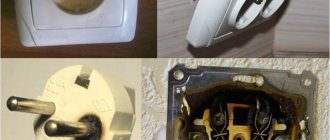
The store advised me to connect the generator directly through the outlet, but I did not do so for safety reasons. And they offered and sold me this adapter:
Cable with plugs for connecting the generator to an outlet
To make using the generator safer, I made the following socket for it on the wall of the summer kitchen:
Generator socket
The SSI-114 type socket has a cover that protects live parts. But there will always be voltage on it - both when the generator is running and from the street! I secured it higher so that the children couldn’t reach it.
I made another adapter for connection so as not to confuse it with anything else, and signed the danger warnings.
Connection cable
The fork looks like this:
Generator output plug
This is the most dangerous place in the structure. But how to avoid trouble is the secret in the connection sequence, more on that later.
Generator, electrical network and automatic heating boiler
A standard generator, designed according to the classical scheme, produces a sawtooth sine wave of the mains voltage, so it is advisable to use an inverter generator for a heating boiler that produces voltage in the form of a pure sine wave (wave). The frequency from a conventional generator is generated with a value different from the industrial frequency of the alternating voltage network of 50 Hz. The voltage is also different from the standard 220V voltage. And many, for example, gas heating boilers require voltage with a clearly defined neutral and phase, while in conventional generators there is no clear phase.
To ensure a high-quality connection of the heating boiler from the generator, it is necessary to use a UPS, and it is better if it has a double converter. It is possible to install a power source with built-in batteries or an accumulator, in which case the UPS will act as an AC converter, which will allow the user to gain a few minutes to start the generator and maintain continuous operation of the heating boiler. The same generator can be used as a battery charger.
The boiler and the circulation pump, its presence in the heating network is necessary, will not fail after power is supplied from the generator, but this probability is nevertheless present, it always increases with periodic use of the generator to power the boiler.
Fig. No. 3. Connection diagram of a heating gas boiler from a generator via a UPS.
An ideal option for an on-line type UPS. Its advantages:
- Voltage to the heating system will be supplied continuously.
- The heating boiler has a clearly marked neutral and phase, this is necessary for boilers with a combustion sensor.
- The voltage sine wave has a pure appearance.
- Excellent network voltage stabilization, the UPS copes with the task of protecting against high-frequency pulses and interference from welding equipment.
- Ability to cope with increased quality of mains voltage without a voltage stabilizer.
- Increasing battery life up to several days, especially if you install high-capacity batteries.
Safety rules required to be followed when operating a generator feeding a heating boiler.
Connection diagrams
Please note that the procedure for connecting the device may differ depending on the type of electrical network.
Connecting devices to a single-phase network
Connecting such a switch to a single-phase circuit is possible only if the selected device is made in a two-pole version. It is also necessary to keep in mind that this device can only function with a power supply whose operating voltage is 300 V.
- For such a modification, the negative resistance indicator will reach 50 Ohms. An important point is that sometimes these switches are supplemented with counters. But such a device as switches can rarely be found when using changeover switches.
- When choosing jumpers to ensure contact between two-pole modifications, only those made of copper should be used.
- To install such devices in residential buildings, you should make sure that there are electrical panels of the KK202 series and other modifications. Due to the discrepancy in performance characteristics, reversing units are not recommended for single-phase circuits.
Connecting the device to a two-phase network
If we talk about the voltage limit with which they are able to cope, then this is the level of 300 V. In such a combination, these switches will be subject to a load that will be about 20 A. Most often, the choice is made on such models of switches, which represent the PP30 series.
According to their design, they are equipped with only two modules. With this design, they will be able to provide an output voltage corresponding to a value of 350 V. The blockers used in them can have different designs
For servicing residential buildings, it is important to ensure that there is an electrical panel. This is a requirement
But the design of control units usually contains thyristors. For the network, the limit of negative resistance is 40 ohms. The contact systems that are implemented in such switches are applicable only to closed-type models. In this case, control of electricity fluctuations is ensured by feed-through capacitors. A device such as a reversing unit performs the task of maintaining the required current frequency. If the choice was made on two different models, then they must be used in combination with the controller. This, in turn, makes it possible to minimize the negative effect of nonlinear distortions that appear in the circuit.
Connection diagram to a three-phase network
In the case of installing a switch in a three-phase circuit, it is necessary to use power supplies with an operating voltage of 400 V. It is worth noting that for such purposes it is allowed to use transformers made exclusively in the pulse version.
- The procedure for connecting the device itself is performed using an inverting input. The output current is supplied through a special device, the role of which is performed by pass-through capacitors. For such cases, it is advisable to use switches of a two-module design.
- At the same time, single-module modifications can also be found on sale. Their feature is the minimum threshold voltage limit, corresponding to a level of 350 V. As for the negative resistance indicator, its value in the circuit can correspond to a value of 55 Ohms. To solve this problem, care should be taken to ensure that the design of the switch contains a device such as a blocker.
- Residential buildings must be equipped with special electrical panels, representing the KK22 series. Control units used for such situations can include in their design not only thyristors, but also dinistors.
Two-way modification
When choosing such changeover switches for a generator, you should keep in mind that they can only be used for single-phase circuits. Its design includes 2 pass-through capacitors. For sale you can find not only two-module, but also three-module models. They can work in combination with power supplies having an operating voltage of 300 V. The connection diagram for such a switch may involve the use of a meter. The installation of such a device itself is carried out using jumpers made of copper. Such switches can only work in combination with expansion type switches.
An important point is that electrical panels of any design are suitable for such devices. The changeover switch used for the generator is designed for a threshold voltage, which is 350 V. As for the load parameter, it can have different values. The determining criterion here is the manufacturer of the product. On average, this indicator reaches 30 A.
How to connect a generator to the network at home: diagram
The circuit is made for an electrical network and a generator. Switching can occur in manual or automatic mode
It is especially important where the insertion point of the switch is located. It must be located after the electric meter, but before the protective device
Let's first study the manual switching circuit. If the voltage disappears, use a switch or circuit breaker to break the connection to the central network and activate the generator. The switch must not implement these two actions at the same time. Be sure to provide a neutral position in the installation for subsequent connection.
It turns out that changeover or reversing switches can serve as a manual switch. When making a choice, you need to take into account the rated currents so that they are not lower than what is consumed. The process of how to connect a generator to the network at home varies. The layout and even the design of the devices may also differ. Look at the image below. It shows the connection of a three-phase generator.
In addition to the manual method, sometimes an indicator is installed that determines the presence or absence of voltage in the centralized network. An example of devices would be 220 V modular indicators or 220 V light indicators (twenty times cheaper), which have a closed housing and ready-made wiring. Their disadvantage is that they are connected to the fuse.
When automatically switching an electric generator, as the name implies, the process occurs without human intervention, automatically. The function falls on the ABP block. It consists of various devices: switches, indication parts, voltage control relays, contactors.
Such a generator must be equipped with an electric starter. To enable the reserve, the centralized network is turned off, the generator starts, warms up, and the wiring is connected to the consumer network. If voltage is supplied to the network again, the process is turned off in the reverse order.
Backup automatic entry can be carried out by different systems. You can look at the process by taking the GG700E gasoline generator model as an example. The connection starts after the voltage from the centralized network disappears. In just twelve seconds, all consumers at home will be provided with electrical energy.
The system is also capable of monitoring the stability of the energy supply. If operation occurs smoothly and continuously for more than ten seconds, then power begins to be supplied again through the common network. The device continues to operate for a few more seconds to check, and then turns off.
What does a pass-through switch look like and work?
If we talk about the front side, the only difference is: a barely noticeable arrow on the up and down key.
What does a single-key pass-through switch look like? You see there are double arrows
If we talk about the electrical circuit, everything is also simple: in ordinary switches there are only two contacts, in pass-through switches (also called changeover contacts) there are three contacts, two of which are common. There are always two or more such devices in the circuit, and they are switched using these common wires.
The difference is in the number of contacts
The operating principle is simple. By changing the position of the key, the input is connected to one of the outputs. That is, these devices have only two working positions:
- input connected to output 1;
- input is connected to output 2.
There are no other intermediate provisions. Thanks to this, everything works. Because the contact switches from one position to another, electricians believe it is more correct to call them “switches.” So a pass-through switch is also this device.
In order not to rely on the presence or absence of arrows on the keys, you need to inspect the contact part. Branded products should have a diagram on them that allows you to understand what type of equipment you have in your hands. It is definitely found on products from Lezard, Legrand, and Viko. They are often absent on Chinese copies.
This is what the changeover switch looks like from the rear
If there is no such diagram, look at the terminals (copper contacts in the holes): there should be three of them. But not always on inexpensive copies the terminal that stands alone is the input. They are often confused. To find where the common contact is located, you need to ring the contacts with each other at different key positions. This must be done, otherwise nothing will work, and the device itself may burn out.
You will need a tester or multimeter. If you have a multimeter, set it to sound mode - it beeps when there is contact. If you have a pointer tester, ring for a short circuit. Place the probe on one of the contacts, find which of the two it rings with (the device beeps or the arrow shows a short circuit - it deviates to the right all the way). Without changing the position of the probes, change the position of the key. If the short circuit is missing, one of these two is common. Now all that remains is to check which one. Without switching the key, move one of the probes to another contact. If there is a short circuit, then the contact from which the probe was not moved is the common one (this is the input).
It may become clearer if you watch a video on how to find the input (common contact) for a pass-through switch.
Advantages and disadvantages of switches
It remains to consider the advantages and disadvantages of these devices. The advantages include:
- Visibility. The device usually has an open or semi-closed design, which means that its serviceability can be verified visually. Well, since you can clearly see the conductive knives and tires, it will not be difficult to determine in what position the breaker is located.
- Simple design. Almost all such switches, including changeover switches, have an extremely simple design. They are very durable, easy to maintain, and their repair usually does not require high qualifications and is inexpensive.
- High switching power/cost ratio. This is perhaps one of the main advantages of the devices. Some of these devices can switch currents of hundreds of amperes, and are relatively inexpensive.
But switch-type switches also have disadvantages. Here they are:
- Increased danger for the operator. Since most devices have an open design, it is very easy to get energized if handled carelessly. Therefore, only qualified personnel are usually allowed to work with such switches, and the switch itself is often placed in a closed cabinet or housing.
- Irregular switching time. The switching speed of almost any switch depends only on the operator’s reaction. When the knives are slowly moved under load, a high-temperature arc can “stretch” between the opening contacts, which is equally dangerous for both the equipment and the operator himself*.
Arc suppression inserts, which are equipped with some types of switches, help fight the arc only partially. That is why the vast majority of electrical equipment manufacturers recommend switching using switch devices only after removing the load using intermediate circuit breakers.
How to connect a power plant to a house via a changeover switch
Remember that the generator must be completely disconnected from the existing electrical network, i.e. It is necessary to disconnect not only the phase, but also the zero.
The simplest and most inexpensive ways to connect a generator to your home with your own hands:
- Through a changeover switch (in the picture on the left).
- Through a three-way reversing switch or three-position switch (in the figure on the right).
If the changeover switch is installed separately, then the three-way changeover switch is provided for mounting under a standard DIN rail in the electrical panel. For a single-phase network, two poles are sufficient (for a phase + zero break), and for a three-phase network, a four-pole one is required (for a three-phase ABC and zero break).
Three lines are connected to a three-way switch or changeover switch: one from a stationary power supply network, the second from a generator, and the third to electrical consumers. They have three switching positions:
- Mains power is on.
- Generator power is on.
- Everything is disabled.
The design of a changeover switch or three-way switch eliminates the possibility of simultaneously turning on a stationary power supply and a generator. That is, either the power plant is turned on, or power from a stationary electrical network is turned on, or everything is turned off.
Let's look at the do-it-yourself connection diagram for a changeover switch. The three-way switch will be connected in the same way according to the diagram printed on it or from the instructions.
All work must be carried out only after removing the voltage, checking its absence and taking measures to prevent its accidental activation.
An external power supply is connected to the upper jaws or contacts, a power station to the lower ones, and home electrical consumers to the middle ones.
In the event of a power outage, you must:
- Start the electric generator manually and give the gasoline generator a few seconds to warm up.
- Switch the changeover switch to the lower position as shown in the diagram.
When voltage appears in the external power supply, switch the switch to the previous position and then turn off the generator.
Switch design
Installation of a reversing switch in the distribution panel
The reversing automatic machine has the form of a box with a built-in blade contact system and spring brackets. When closing the first, metal blades enter the brackets. Thanks to this operating principle, contact rupture under its own weight is eliminated. There is a smooth redistribution of electricity from one line to another.
You can fix the switch on the wall in any position - horizontally, vertically and even diagonally. This does not affect its performance.
Expert opinion
It-Technology, Electrical power and electronics specialist
Ask questions to the “Specialist for modernization of energy generation systems”
Connection diagrams A reversing switch is an excellent solution for safely and error-free load switching from one supply line to another. Ask, I'm in touch!
Installation and connection rules
Changeover switches are installed inside distribution boards - ASU. For modular devices, standard DIN rails are provided. The dimensions of the shield are selected according to the number of installed modules. Switches in the usual design are mounted on specially designated mounting panels. A DIN rail can also be used here to accommodate modular protective equipment.
Shields made of plastic or metal are used indoors, and only metal products with the required degree of protection are installed outside.
The main cable supplied from the metering board is connected to one of the inputs of the switching device. The other input is for the backup cable connected to the generator. If the switch has only one output, a cable coming from the distribution panel is connected to it. Modular devices usually have 2 inputs and 2 outputs. The outputs are connected in parallel using jumpers, after which they are connected together to the distribution board.
Such a connection is clearly visible in the example of a single-phase network, to which a three-pole changeover switch is connected, connecting the generator to the electrical network. The main requirement for carrying out such a procedure is to maintain polarity. Correct connection will allow you to avoid changing the positions of phase and zero when making switchings. At the network input, protection is installed in the form of a circuit breaker located in the metering panel. The input coming from the generator is also protected by a machine installed in the panel along with the switch.
Connecting the device can additionally use automatic transfer of a reserve - ATS, or the reserve is switched on manually using an automatic machine. In the case of using changeover switches, such switching is performed without load. First, the load is switched off automatically, and only then all the necessary manipulations with the switch are carried out.
If the design of the switch includes an arc extinguishing device, then switching can be done directly, without first turning off the machine. However, the circuit on all lines must necessarily include fuses or circuit breakers, since the switch itself will not be able to protect the network in an emergency.
Operation of the changeover switch will be safe if you follow the installation rules and recommendations of specialists:
- For installation and further work it is better to use a closed room.
- Switching equipment is reliably protected from moisture and negative external environmental influences.
- The temperature limit at which normal operation is possible is from minus 40 to plus 55 degrees.
- Installation of the changeover switch and its fastening must be strong and reliable.
When installing the device outdoors, you should first ensure protection from external influences. At possible low temperatures beyond the permissible limits, a heating system for the cabinet should be provided in advance. All work on installation, maintenance and repair of switching equipment must be carried out by qualified specialists, with the network completely disconnected.
Types of switches for generators
When choosing products for generators, it is best to give preference to single-module switches. If we are talking about a blocker, then it must be equipped with a classic contact system. The design of reversible blocks often contains a controller. That is why you should not opt for systems with a resonator.
In such situations, the threshold frequency will be high. Products used for generators may vary in size
It is important to pay special attention to the number of capacitors
Before installing generator products, it is necessary to carefully study the grounding system. Full operation of the device is possible in the presence of a grounding electrode. The labeling of the latter must necessarily contain information about the protection system, in most cases this is IP30. Based on this information, you can safely judge the reliable insulation of the device. Such a system will function over many cycles.
Two-way systems
When purchasing changeover switches, it is important to take into account the fact that they can only be used in single-phase circuits. The design must contain two pass capacitors
Manufacturers produce not only two-, but also three-module systems. They can operate with a power supply having a voltage of 300 V. The connection diagram for such a device often involves the use of a meter. Installation is carried out using copper jumpers. Operation of the units is possible in conjunction with expansion switches.
Changeover switches are designed for a voltage of 350 V, the load may vary. The determining factor is the manufacturer. The average load is 30 A.
Three-way modifications
If we look at these changeover switches in detail, it is important to note that they are equipped only with expansion switches. This is the most suitable option for use in two-phase circuits
Products are in wide demand on an industrial scale. Their operation in an enterprise is possible if connected to an electrical panel of the KK202 series.
Often, jumpers are made of copper; blockers may differ in design. A feature of the products is a high sensitivity limit. In addition, they are equipped with a reliable protection system. Insulation comes in different classes. The determining factor when choosing is the manufacturer.
Thus, products of the SFT 250A series are installed exclusively in conjunction with power supplies with voltages of 200 and 300 V. The connection diagram for such devices provides for the use of pass-through capacitors. This is necessary so that the load is no more than 3 Amps. Often systems operate with analog switches. In addition, units manufactured in an expansion version are common.
. When connecting meters, they need to be allocated a special place behind the contact system. Reversing units must be equipped with a resonator and a controller. The choice must be made taking into account the peak frequency of the product.
Generator switches are an effective solution and provide many benefits. In addition to convenient maintenance, it is possible to monitor network characteristics. This minimizes the risk of dangerous situations affecting the functioning of devices connected to the network
When choosing devices, you need to pay special attention to the parameters of the included elements, as well as the room where installation is planned
Type of devices
The most common type of changeover products is single-module switches. They are often equipped with copper conductors. It should be borne in mind that such units are best used for generators with operating rates of no more than 20 Hz. However, there are certain disadvantages that should not be neglected when choosing.
It should be noted that during the operation of single-pole products, the maximum load on them can be no more than 200 Amperes. Therefore, it is better to avoid installation in residential areas where a lot of electricity is consumed. In addition, they have a low output voltage of 200 V.
Today, changeover-type devices with two poles are often used. Most often they are installed in residential premises. Switches can operate in both single-phase and two-phase networks. Average negative differential resistance data is 60 ohms.
Output voltage readings may vary. The modification of the product depends on this.
Nowadays, devices of the PP20 series equipped with open capacitors are mainly used. The connection system provides for the presence of a power supply with a voltage of 300 V.
Application of ABP
The autostart system is more expensive than the manual one, but it constantly monitors the network voltage. When the voltage disappears, the contactor interrupts the connection between the ATS and the central power grid. The starter turns on and the generator starts working. Most generator owners prefer using cheaper partial automation, which works as follows:
- The main power supply is connected through a contactor that opens when the input is disconnected.
- The gas generator is started manually. A time relay is installed in it to warm up the engine and automatically switch to connecting the reserve to the home network.
- When the power supply is restored, the contactor is switched off and the load is supplied again from the public network.
A fully automated power supply system regulates the operation of the gas generator using microprocessors. Video on this topic
Changeover switch principle of operation
An electrical type device that serves to disconnect an electrical load from one energy source and connect it to another source is called a changeover switch, or a changeover type switch (switch with a midpoint). The devices are available with or without arc arresters. In the first case, network switching can occur with a fully connected load. In the second - only when it is turned off.
The switch is operated manually, that is, if it is necessary to switch power sources, the operator acts on the isolated control lever of the switch. There are also automatic switching systems.