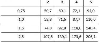
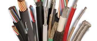
SIP is a self-supporting insulated wire. It is called self-supporting because it contains, as a rule, in the zero core or separately, a steel wire core, which allows the wire not to stretch under its own weight. This wire is intended for use in overhead power lines, that is, for pulling “at height.” In addition, it is they who usually carry out the pulling of the overhead line from the highway to the house.
The design of this wire does not involve the use of terminal blocks, much less twists. Moreover, a direct connection of two SIP wires is not made at all, since they can transmit current with a voltage of up to 35 kW. For electrical interfacing of self-supporting insulated wires, special piercing clamps are used.
SIP laying
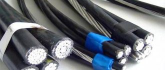
SIP is a single-phase or three-phase wire, the phases of which are insulated with durable polyethylene, resistant to ultraviolet radiation, and the neutral wire is the load-bearing wire.
This is an aluminum strand braided around a steel core. The neutral carrier wire can be insulated or not; three insulated phases are wound on top of it. Such a wire works in the distribution of electricity from transformer substations within the building boundaries, which, in general, justifies the increased concern for safety. These wires are insulated very well and hermetically, since external wiring is subject to all natural influences.
When laying SIPs, they are pulled from support to support, the two wires are joined to each other using a sealed clamp, which is crimped. Thus, the contact of the spliced wire and the insulation of the SIP cable along the entire line from beginning to end remains sealed.
To connect a branch line to the main line, specially designed self-piercing branch clamps are used. The technology in this case does not require removing the insulation from the wire; the clamp connects two wires using a puncture method, and the clamp itself creates reliable insulation of the branch from the outside.
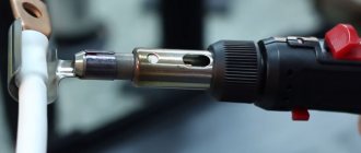
The technology is as follows:
- Install the clamp onto the main insulated wire through the hole provided for this purpose and securely fix it.
- Pass the external connecting wire through the second hole.
- Using a wrench (usually 13 or 17), tighten the clamp head. The dosage of force for the cable is that when twisting, after piercing the insulation of both wires inside the clamp and creating reliable contact, the head breaks off, and the contacts inside the clamp are securely fixed.
- After the head comes off, the connection is reliable, and the insulation is solid and sealed.
- The end of the branch conductor is sealed with a special cap.
Types of SIP anchor clamps
The SIP is secured to the bracket itself on the wall using anchor clamps. Their brand depends on the cross-section of the wire and the manufacturer.
Ensto anchor SO 243, SO 157.1, SO 158.1, SO 80
Anchor IEK ZAB and ZAB
Anchor KVT ZAB
Anchor Sicam GUKp
Anchor Niled DN 123
And the pivot table:
| Manufacturer | Anchor clamp brand |
| ENSTO | SO 243 - SO 157.1 - SO 158.1 - SO 80 |
| IEK | ZAB - ZAB |
| KVT | ZAB |
| SICAM | GUKp |
| NILED | DN 123 |
For example, what is the difference between an SO243 and an SO80 clamp? Both seem to be suitable for a 16mm2 SIP section.
Imagine that your entrance to the house from the pillar passes across the road. And one fine day, a truck with an oversized cargo will catch the SIP, tightly secured to the bracket with a powerful anchor. The jerk will be so strong that it could easily tear out a piece of the facade.
And if there is an anchor clamp with less tensile strength, then it can simply tear the wire from the fastener, leaving the wall of the house untouched.
By the way, the same thing should happen on the sealing support.
Terminal markings
The markings of piercing clamps produced by different companies may differ from each other. It should contain information about the cross-sections of wires - main cable and branch. The defining parameters are the ranges of wire cross-sections.
For example, the marking, which has been in operation for more than 20 years, is as follows: ZPO 16-95/1.5-10, means: branch piercing clamp, main wire cross-section from 16 to 95 mm 2, branch wire cross-section from 1.5 to 10 mm 2 .
Here is an approximate range of piercing clamps from the company
- ZPO 16-95/1.5-10
- ZPO 16-95/4-35(50)
- ZPO 50-150/6-35(50)
- ZPO 50-150/50-150
- ZPK 35-95/4-54
Piercing clips in a rubber housing.
List of main characteristics
The characteristics of clamps of this type are determined by the following parameters:
- The number of branch SIPs that connect to the main core (usually from one to four).
- Cross-section of the main core (mm2).
- SIP cross-section (mm2).
- Maximum current load (A).
- Product weight (g).
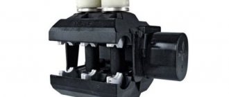
As an example, we give a table of characteristics of NILED connecting fittings.
Characteristics of NILED connection clamps
Types of parts
The industry envisages the production of several types of clamps for SIPs. All of them are designed to work in certain conditions.
Branch piercing with one bolt
This type of clamp is also often called a bare clamp. It is used to lead the wire (uninsulated) to the vulture.
Distinctive features:
- Section from 16 to 95 mm.
- The polymer housing of the clamp can prevent UV rays from penetrating inside and is also resistant to various weather conditions.
- The branch clamp has a stable bar.
In this case, the branch piercing clamp is made of aluminum (alloy), which prevents rust
. Both the bolt and the mechanism are reliably made.
Piercing branch with two bolts
A tap component is used to route bare wires to the main trunk line to the sip line. The cross section can reach 95 square mm. The body uses highly resistant glass-reinforced polymer. For convenience, the branch clamp has a lower bar that helps fix the key in a given position.
This item will last a long time
, since it is resistant to moisture, wind and other manifestations of the external environment. Manufacturers, as a rule, are responsible for quality, so in this case you can count on it.
When choosing a clamp for SIP, it is worth remembering that the bolt head must be proportional to the key. most commonly used head is 13 mm
. Sometimes you can find 17 mm, but much less often. The size of the wire cross-section indicates the thickness of the line. From this size you can understand the size of the branch that should be mounted in the branch clamp. When choosing this part for SIP, you need to remember all these simple rules.
When designing electrical wiring, all issues that relate to running the cable to the input circuit breaker are often ignored, since this point is taken for granted. However, installing a piercing clamp for SIP wires is a very responsible undertaking that requires full mastery of the technology. When conducting wires, you must be guided by two bases - durability and safety.
In addition, it is important that any element or part of the chain can be reached without problems for the purpose of repair or replacement. In this article we will look at the principle of operation, purpose and installation features of a piercing clamp for SIP wires
Purpose of the clamp
In the vast majority of cases, a piercing clamp is used to conduct electricity into a particular room (house, garage, barn) from the main line. The principle of operation is to pierce the main cable with a special device, after which aluminum single-core SIP wires are connected in the clamp body through special terminal clamps protected from external harmful influences (electricians call them nuts).
Another wire coming out of them is fed to the input circuit breaker for further distribution of the electrical network throughout the room.
Errors when connecting branch lines to the main line
- When installing the clamps, do not press the head completely. There may be a bad connection.
- Second time use branch clamps. Even if it looks like a working new one, during the first installation the cutting teeth may have been damaged (bent, broken), and contact in this case may not be possible.
- Connect wires that do not branch off from the main line, but are equivalent to each other.
- Try to use a clamp to connect not one, but two lines. Since the cutting contacts are centered along one core, they must accurately cut through the central part and enter the conductor. Otherwise they will miss or bend.
Installation features
Before installing and using the clamps, you need to take into account the mistakes that consumers make during installation:
- Do not try to unscrew the head after it has been screwed in. It only works to close it; it cannot be locked again. If the fastening is incorrect, the screw must be changed.
- It is not allowed to install more than one core into the product. The contact will be unreliable.
- It is not allowed to connect the cores of the SIP wire during installation - this violates safety regulations and increases the likelihood of a short circuit and fire.
When connecting the SIP piercing clamp, you must use dielectric wedges.
Electricity supply via SIP
Electricity connection to a residential building is most often made using a self-supporting insulated SIP wire. It consists of several phase aluminum conductors covered with durable polyethylene insulation (cross-linked polyethylene) and a zero carrier. It can be with or without insulation. Often, for branches, a wire without a zero load-bearing core is used (SIP-4, SIP-5).
Compared to conventional cable, SIP has the following advantages:
- You can make the connection yourself. If the power line is de-energized, the connection process is completely safe. But if you don’t have the skills to work with electricity, it’s better to turn to electricians for help.
- Reliable power transmission in any climatic conditions. The wire can withstand high and low temperatures, gusts of wind and precipitation.
- Low price and durability.
SIP also has advantages over bare wires, which are also laid through the air:
- no porcelain insulators required;
- the distance between the cores decreases;
- there is no overlap of wires with each other under the influence of wind;
- Reactive losses are reduced due to the presence of insulation;
- Wire installation is simplified.
Why you can’t bring SIP into your home
First, the official information. According to GOST 31946-2012, according to which all SIP wire is produced in our country, “3.1 self-supporting insulated wire:
Stranded wire for
overhead power lines (...)”.
The exception, as I said, is only for the wire with the letter “n” - it can be laid along the walls of buildings from the outside. And even then – at a certain distance from the surface. The additional letter “n” in the marking indicates the fireproof design of the SIP. The polyethylene insulation of such wires is self-extinguishing and does not support combustion. However, such a wire cannot be brought into the house either.
A special feature of SIP insulation is that its insulation is designed for outdoor use. This means that it is resistant to sunlight. Cable insulation for indoor wiring must have a very low flammability, and resistance to sunlight is not important here.
Since SIP insulation is made of polyethylene, which burns with the formation of burning molten drops that set fire to everything around, the limitations on the scope of SIP use are understandable.
Some readers may have a question: why does it have to light up? After all, no one will deliberately set it on fire in the house. Here we remember the beginning of the article. Where it was said that a fire can occur at any time due to improper connection.
The main cores of SIP are made of aluminum or its alloys. As you know, aluminum is a soft metal and the contact connection tends to weaken over time. If the contact is not tightened in time, it will heat up. When heated, the contact resistance will increase, which will lead to even greater heating and cause arcing of the contacts. The problem grows like an avalanche: more heating - worse contact - more heating, etc. Aluminum “flows” inside the terminal and its tightening becomes weak.
The situation is complicated by the fact that the aluminum wire and the terminal material of the machine or meter (copper-brass alloy) have different temperature expansion coefficients.
This means that a situation may arise when the contact deteriorates and heats up so much that the SIP insulation begins to melt or catch fire. As an example, I will give a few photographs. Three-phase input to a circuit breaker in an electrical panel:
The result of incorrect connection of the SIP to the terminals of the circuit breaker. The counter also got it.
As you can see in the photo, due to poor contact and probably considerable load, the wire got hot, which led to the melting of the insulation, which began to flow down the body.
SIP insulation melted due to heating and flowed down
In the event of a fire, such insulation, continuing to flow, could possibly set fire to the entire panel. The photo clearly shows that the insulation was severely melted, and the owner decided to “fix” it with electrical tape.
SIP wires - the insulation melted due to heating
That is, the problem did not arise suddenly, they tried to eliminate it.
It is not the effect that needs to be eliminated, but the cause. And the reason here is an incorrect connection. One might say that the technology has not been followed. But more on that below.
When heated, a short circuit occurred and two wires burned out. One core remained intact (phase on pole 2). And two wires are soldered together and at the place of soldering you can see a burnt-out insulation (hole). There was little time left before the short circuit. The worst thing about this situation is that in the event of a fire, turning off the power supply would be problematic.
The same electrical panel in which the input circuit breaker was promptly replaced:
Reconnection of SIP and installation of a new input machine
Moreover, the ends of the SIP are again connected in the same way. This means the problem may repeat itself. Plus - it should be noted that the rating of the installed input circuit breaker is lower (it was 63 - now 40 A), which means that the maximum current of the SIP will be lower. But the question is: how long will it last? – remains relevant.
While we're on the subject, a couple more mistakes in this closet. After the introductory machine there is a nominal value of 63 A. It is unlikely that choosing such a large nominal value is advisable and safe. By the way, phase burnout is not as scary as zero burnout. If there is poor contact at the points 4th pole of the machine - 4th pair of meter contacts - bus N, not only a fire is possible, but also damage to single-phase household appliances. If you do not agree with me, read the articles What is a zero break in a three-phase and single-phase network and Three-phase electrical panel diagram - I answer the reader’s questions. I also described how to connect a PEN wire to the metering panel in the article Electrician in the mountains of Georgia. Well, there is no grounding, from the word “at all”.
Moreover, keeping in mind the possibility of SIP fire, it cannot be installed on flammable surfaces, even outdoors. Here is a photo sent by a reader. Here the “street” is the wall of a wooden country house:
SIP is turned on automatically on the external wall of a wooden house
The outgoing cable is not yet connected. I advised the reader to place a metal or asbestos substrate under the box, and take care of the quality of connecting the SIP to the terminals of the machine, which will be discussed below.
Advantages of branch compressors
In work, the use of such technology provides a number of undeniable advantages, in particular:
- Ability to work under voltage. Using the clamp, you can make a tap from the main SIP without de-energizing the line.
- The ability to connect wires made of different metals (copper and aluminum), provided that they are single-core.
- Tightening control - using a breaker head (in particular, in the P95 branch clamp it is aluminum) or using a dynamometer. In the first case, breaking the head means achieving the required pressure.
- Convenient removal method using a second screw.
- The case is hermetically sealed for the corresponding models. Leak tests are carried out in water using high voltage current.
- Compensation for temperature expansions.
- Speed of installation work.
- There is a wide range of wire gauges that can be connected this way.
Wedge characteristics
The use of plastic separating wedges will be more rational, since they:
- have comfortable grooved handles that prevent slipping during use;
- the material used in manufacturing is highly durable;
- sets of wedges are fastened with a rope, which prevents the possibility of the wedge falling out during use on the support;
- will not damage the insulation of the wires.
They are usually used during installation work on SIP conductors to separate the cores from the general bundle.
OZPI
The technology of modern branch clamps with insulation piercing (IPPI) is developing in the following areas:
- improved contact system;
- new materials for the manufacture of clamp bodies;
- controlled tightening force of the main bolt;
- increased tightness of connections;
- increasing ease of installation.
Modernization of contact group
- Plates made of aluminum alloys and with pyramidal-shaped teeth, placed in a checkerboard pattern (Fig. a below).
- Aluminum or copper plates with wedge-shaped teeth like a saw (Fig. b).
- Aluminum plates that combine the advantages of previous types (Fig. c).
OPPI devices from popular manufacturers: a – Ensto; b – (1 – Sicame and Simale, 2 – Niled); c – Sicame and Simale
Any of the three methods guarantees the creation of a puncture of insulation and reliable electrical contact with the current-carrying core of the SIP. The material of the phase wires is softer than the neutral wire and the teeth penetrate deeper into them. In any case, the shear head of the tightening bolt ensures the creation of reliable electrical contact while maintaining the required strength of the conductor.
The housings shown in Fig. The above models are made of glass fiber reinforced polyamide. They have good mechanical and electrical properties and withstand weathering well.
The tightening process of the main bolt is controlled due to the shear head. It provides only one-time use of the OPPI. However, you can use a torque wrench to create the required force. This option was used in early models of devices, but it turned out to be not very convenient.
Using specific torque charts for different models, you can use a torque wrench for secondary installation. In this case, you cannot be completely sure of the reliability of the connections, since the piercing teeth in the clamp used are deformed.
Installers prefer models with minimal tightening force.
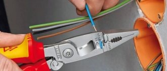
Connection to SIP
To connect to the power line, you need to have piercing branch clamps, a SIP for the branch and a wrench.
Despite the fact that the clamps eliminate the possibility of electric shock and the wires are insulated, personal protective equipment must be used. These include rubber gloves and a mat, as well as a dielectric wrench.
The wires of the main line should be separated one by one from each other, driving dielectric wedges between them (Fig. below). If you don't have them, you can make them wooden.
Dielectric wedges are used to separate the main line wires from each other.
A wedge is inserted between the cores, and the bundle is untwisted several turns in the direction opposite to the winding. Then a clamp is put on the core. For the main it goes right through, but for the branch you can only connect on one side; on the other, the terminal is closed with a cap.
Installing the main (bottom) and branch (top) wires into the clamp
The branch connection wire is straightened at the end and inserted into the clamp hole until it stops (Fig. above). In the contact terminal system, the conductors must be arranged in parallel.
When connecting wires, follow their markings.
With smooth contact surfaces, the insulation from the connected sections of current-carrying conductors is removed (solar clamps). To do this, first a clamp is applied to the installation site, 2 marks are applied to the insulation, after which it is removed with a cable cutter. When installing this way, the line must be de-energized.
The branch conductors are stripped in the same way. Then the clamp is installed and the wedge holding the wire is removed. At a distance of 15-20 cm from it, bandages are installed on the SIP.
Installation work with SIP wires is carried out at height. The confidence of the installer and the complexity of the operations depend on how correctly the fittings for installation are selected.
Design
Structurally, the SIP clamp consists of:
- Waterproof or sealed housing (the latter is preferable).
- A kind of internal “terminal” made of one or more symmetrical plates with pyramid-shaped spikes, which are located in each of the sockets.
- A fastening system based on the use of a breakaway calibrated screw head.
- Additional clamp release system designed for emergency removal.
Inside the case there is a special lubricant that seals the puncture site, preventing water and air from coming into contact with the wire. This is also facilitated by the specific shape of the teeth.
The SIP clamp is tightened with an ordinary bolt with a 13, or less often 17, head. In total, the system has two bolts - one with a breakaway head, the other a regular one, which, if necessary, can be loosened to pull out the wire and disassemble the entire structure.
There are 2 or 4 sockets for wires. They can be of different diameters, for example, 16–120 and 6–50. Here the first group of numbers is the cross-section of the main wire, the second is the additionally connected one. One of the advantages of SIP clamps is that they (within certain limits) can be adjusted to fit cables of various calibers.
There are two main types of these connectors - with a breakaway head and with a torque wrench, which can be used to set the clamping force. In models with a breaking head, breaking occurs at a force of 9 to 20 Newtons (depending on the model). The same compression force must be achieved when using a modification with a torque wrench, since it is necessary that the teeth pierce the insulation and reliably enter the metal core. In this case, the teeth are significantly deformed - this, in combination with the breaking of the head of the clamping bolt, makes the clamp for SIP disposable. The fact is that, in order to combat the formation of oxides, the plate with spikes in the clamps is made of a relatively soft aluminum alloy. This is its difference from “piercing” terminal blocks.
There is no electrical contact between the connecting screws and the serrated plates. The housings are made from various polymer materials that are UV resistant and often have additional fiberglass reinforcement.
Kinds
Insulated branch clamps (ZOI)
How to connect SIP with copper cable
The devices are used to connect phase and neutral SIPs with voltages up to 1 kV to overhead lines. In Fig. The branch connections to the main wires are shown below. Here the self-supporting core is suspended from a support clamp (top right). The piercing clamps are placed on the wire and tightened through the breakaway top head of the bolt. It provides a certain force for pressing the teeth against the wire in order to ensure electrical contact without damaging it. The clamp can later be removed with a wrench by unscrewing the lower removal head, which remains undamaged.
Branch connection to overhead lines using piercing clamps
Clamps ZOZRB IEK
Clamps are used to branch one or two conductors simultaneously from one main wire. The connection is used in objects where there is little humidity and water cannot enter it.
The purpose of a particular type of clamp can be determined by the markings. It indicates the number of branch conductors. If the bolt head is shear, the designation “C” is entered. Sets of numbers separated by a “/” sign indicate ranges of conductor cross-sections on the main and branch lines.
The difference between the IEK clamp and the others is that the piercing teeth are located only on the main wire, and on the branch wire the insulation must be removed at the point of contact. The method allows you to use any type of conductor for the branch, for example, VVG cable.
Manufacturers
Leading companies producing valves are Ensto, Niled and others.
Ensto
The Finnish company Ensto produces fittings for all types of SIP. Lightweight models are available, made of plastic, as well as those made of durable alloys for harsh working conditions. A feature of the piercing clamps produced by the company is the pyramidal design of the teeth, which increases the contact area and reduces the penetration of teeth into the wire, which reduces its damage. This contact part is similar in characteristics to clamps in the form of dies.
Niled
The French company Niled is the main supplier of fittings for SIPs in Russia. A characteristic feature of the products is adaptation to local conditions. Insulation piercing devices for domestic small-section wires have been developed for the Russian market. The range of supplies meets the technical requirements of RAO UES divisions.
Other types of clamps
It is almost impossible to give a complete description of clamps of all types and types - there is too much variety. A device that deserves special attention is the RS 481. It is designed for connecting electrical measuring instruments, short-circuiting and protective grounding of lines, mounted at the beginning and end of the line for the entire service life.
Another notable type of SIP fitting is the simultaneous clamp type P70. It is used for branching main power lines with core cross-sections from 25 to 150 mm2. The devices are designed for operation at temperatures down to –60С.
It is necessary to use a branch clamp when laying a high-voltage line, connecting street lighting and for introducing an electric cable into the house. Their use makes it possible to increase the safety of installation and the durability of the created energy network.
Classification of piercing clamps
Punctures for SIP come in two main types. The first is ZOI (insulated branch clamp). It is usually used to connect overhead lines with self-supporting wires at voltages up to 1000 V. Its operating principle is quite simple. The device is put on the desired wire and secured with a bolt, which is tightened until the head is torn off. This method of fastening allows you to ensure the required level of contact between the plates and the wire without damaging it. As a result, stable contact will arise between the main and the branch. If necessary, the clamp can be easily removed by unscrewing the lower bolt head, which is used for dismantling.
The second type is called ZOZRB IEK. It is used if it is necessary to organize a branch of two wires from an overhead line.
Note! This type of piercing clamps has certain limitations during operation. It should be installed in places where there is no high humidity to prevent water from getting inside
Therefore, it can only be used indoors.
The main difference between the second type of product is that it has piercing teeth only for installation on the main wire; the insulation will have to be removed from the branch conductor to ensure a reliable connection. At the same time, such a connecting mechanism allows you to use any type of conductor as a branch conductor, for example, VVG (unarmored vinyl insulated cable).
Connecting the cable to the overhead line using a clamp
Connection clamps
To ensure reliable transmission of current from overhead lines to a transformer or other current consumer via the SIP cable at the point of their connection, special piercing clamps for SIP are used. They are arranged as follows:
- The material from which the body is made is duralumin alloy or fiberglass-reinforced polymer. It can withstand significant loads and exposure to various atmospheric phenomena, which allows for reliable and safe connections in any climatic conditions;
- Special plates made of conductive material, equipped with special teeth. They are the ones who pierce the insulation and ensure the transmission of electricity from the overhead line to the current receiver via the SIP cable;
- Several bolts (but sometimes one is enough) for fixation. The peculiarity of this fastening is that the bolt heads are shearable, which means they can only be used once. This engineering solution was implemented to ensure safety.
Clamping device
This design has the following advantages:
- The contact between the main wire and the branch will be stable and sealed, which will ensure reliable power supply and no failures in the transmission of electricity;
- A high level of safety, which is especially important since the main wire is under voltage up to 1000 V. This is ensured by the presence of high-quality insulation made of cross-linked polyethylene, as well as by the fact that the mounting bolts are not connected to the contact terminals;
- Easy to install. The clamp is designed in such a way that it is not necessary to remove the insulating layer from the SIP cable to ensure connection with the main line; it is enough to simply insert it into the hole of the piercing device and tighten the bolt until its head is torn off.
Branch clamp for SIP wires price
Price for branch clamp for SIP
is an important factor when purchasing. We try to provide the most affordable prices for all products offered, which makes our offer one of the most profitable on the market. The price for a branch clamp is set according to the price list of the plant and the MRP established by the manufacturer. As a leader in the power transmission line equipment market, we are ready to offer the maximum discount on products from NILED and VK.
That is why it is carried out mainly with SIP cable (the correct name is self-supporting insulated wire), since it satisfies the owners in all respects. Its characteristics are a separate topic. But it is worth understanding in more detail the installation features and devices that are necessary for laying out the line (the so-called punctures for SIP cables), since their use has a number of nuances that are not typical when using other types of cables.
The power supply circuit for individual areas is often quite complex, since there may be several buildings on the territory that require connection to the industrial network. In order to make branches from the line, you need not only professional knowledge and skills, but also special reinforcement elements for various connections (couplings and the like).
But the main difficulty lies in cable cutting, connections, and reliable insulation of these sections. It is quite difficult to do all this with your own hands (and this is the most common installation option in the private sector). But when working with SIP, nothing like this is required. For this purpose, there are special branch clamps called punctures. Consequently, the process of assembling an on-site power supply circuit is greatly simplified.
Connection of SIP with VVG cable
When introducing an electrical line into a structure, VVG cable or another similar brand of copper conductor is most often used. Direct contact of copper and aluminum conductors during installation is extremely undesirable. In this case, increased resistance to electric current occurs at the junction, which leads to overheating of the conductors, accelerated corrosion and destruction. Breaking the contact can lead to various negative consequences, including a fire. To prevent this from happening, special methods should be used to separate copper and aluminum conductors from each other.
The simplest of them is to connect a copper and aluminum core using a threaded connection. For this option you will need a steel bolt with a nut of suitable diameter, several simple washers and one engraving washer. Installation of such a connection is very simple: a washer is installed between dissimilar conductors to prevent direct contact of copper with aluminum. It is advisable to choose washers coated with pure tin or solder based on it. After tightening the bolt, the connection must be wrapped with insulating tape. This method is very simple, but extremely unreliable, so it is practically not used.
For a better and more reliable connection of SIP with copper cable, completely different methods are used, which are performed using specially designed connecting elements, such as piercing clamps, monolithic aluminum-copper sleeves and branching clamps. Let's consider each option separately.
- Piercing clamps. With this method, the insulation from the cores of the connected cables is not removed. A copper and aluminum conductor with an insulating layer is inserted into the corresponding hole in the clamp, after which the entire structure is tightened with a threaded connection. Tightening can be done either with one top bolt or with separate bots for each core of the connected cables. The body of the piercing clamp is made of durable polymer material with glass fiber reinforcement. It provides reliable protection to the connection from the effects of negative environmental factors.
- Branching compressions. Among experts they are called “nuts”. These connecting elements have in their design three bimetallic plates and tightening bolts, which are enclosed in a protective housing. To connect SIP to copper cable, you need to remove the insulation from the cores, insert it between the plates and secure with bolts. The use of clamps is more preferable for aluminum cores of self-supporting wires, since they are very sensitive to the notches that arise from the spikes of piercing clamps.
- Bimetallic sleeves. These connecting elements are made of copper and aluminum parts combined into one monolithic structure. The connection of dissimilar cores is carried out by crimping. The conductors are stripped and inserted into a sleeve, which is crimped with a special tool, thereby creating reliable contact. The connection point is sealed with a special heat-shrinkable tube filled with an insulating gel. Under the influence of high temperature, the tube contracts and reliably protects the contact from the negative influence of the external environment.
An alternative to all of the above methods of connecting self-supporting insulated wires with VVG copper cable or other brands is the direct insertion of self-supporting insulated wires into the building with a connection to the electrical panel. The rules of the PUE and the requirements of energy supply organizations do not prohibit this option, as it reduces the possibility of electricity theft.
Instructions for connecting the line to the trunk using a SIP clamp
Before you start work, you need to stock up on tools, safety equipment, have reliable access to the line where you are going to connect, and prepare it and the line to be connected.
Branch clamps are needed that correspond to the parameters of the lines. Wrench (usually 13). Latex gloves. To prepare the main line for connection, you need to find connection points for each phase.
The main line wire is disassembled into phase wires
Since SIP wires are usually wound onto a supporting neutral wire, they should be disassembled into individual phases very carefully, without using metal tools, so as not to damage the insulation. It is enough to free up a little space so that you can insert the clamp with the hole for the main wire
To release the phase wire, you must use a dielectric wedge.
Attention! When releasing the phase wires of the main wire from the twist, you must remember that the main wires are under high electrical voltage, which is life-threatening. Damage to their insulation is unacceptable! Under no circumstances should you push the phase wires apart with a screwdriver, pliers, or anything sharp or metal.
It is necessary to use a dielectric wedge. For greater safety, carry out work with rubber gloves and rubber galoshes.
Attention! Before connecting the branch line to the main line, which is energized, you need to prepare the branch line in advance. She must be:
- mounted, the end of the branch line must be fixed near the connection point so that the free ends of the line wires are sufficient to bring them to the terminals;
- the other end is brought to the wiring point;
- equipped with a disconnecting device (switch);
- in this case, the disconnecting device must be in the “Off” position. There should be a warning sign on it: “DO NOT turn it on, people are working!”
- Let's understand the wires of both lines. If they are multi-colored, then we connect them according to the colors. The most important thing is that the zero phase (blue wire) of the main line is connected to the zero phase of the outgoing line. If there is a ground wire (green-yellow), then it should also be connected to the “ground” wire of the branch. The colors of the phases may differ slightly from each other; the sequence is not so important here, although technical accuracy requires that they correspond to each other, at least approximately.
- Installing a piercing clamp for wires on the main wire of one of the phases. Since the main wire is without a break, a clamp is installed on it through the slot holes. The pre-tensioning bolt must be sufficiently loosened and the clamp must be suitable for the wire gauge range.
- The wire from the phase of the outlet cable corresponding to a given phase of the main cable is inserted with its end into the second hole of the clamp. The clamp must be loosened so much that when passing the wire into the hole, its insulation is not damaged by the sharp teeth of the contact plate (and at the same time the teeth do not bend, since in this case there will be no good contact).
- The head of the bolt of the piercing clamp for SIP is carefully tightened. In this case, both wires and the clamp are held in the normal position so that there are no distortions. We work with gloves!, since after some tightening efforts the insulation will be broken and the phase will flow into the outlet line.
- We continue to tighten until the head of the bolt falls off - this will be the required force so that compression occurs, the SIP is punctured and reliable contact is established.
Connecting the house to power supply
Connecting a SIP from the main line to the house is a subscriber connection and is carried out as part of a new connection or replacing old wires with a SIP. Before connection, a number of bureaucratic approvals are carried out, and the connection itself is made using 2×16 SIP wires, either independently or by calling professionals.
Obtaining approvals for a new SIP connection from the highway to the house
- In your area, you need to find a government agency responsible for energy sales in the area. In them you receive documents that you, as the owner or authorized person, have the right to connect;
- Order and receive a house connection project;
- If there is a support for a main line or a linear branch within a radius of 25 meters from the house, then you will connect from it. If the supports are removed, you will have to “fork out” for the installation of additional support.
Purchasing the necessary materials
For work you will need:
Note. The usual connection is single-phase (phase + zero) and a SIP with a cross-section of 2 × 16 mm2 is used for it.
- Two anchor clamps. The correct name is self-tightening wedge anchor clamps. Company brand NILEDPS 1500.
- Four piercing clips. Brand NILED PS 95– 2 pcs., P 4-2 pcs.
- A screw-in hook or wall bracket for attaching an anchor clamp to the front of a house.
Stages of work on connecting SIP
- Roll out the cable from the support to the house. SIPs cannot be rolled out on the ground, as the insulation may be damaged. Cable rollers are used for rolling;
- Attach the anchor clamp to the facade of the house together with the SIP;
- Pull the SIP from the house to the support. The height of entry into the house must be at least 2750 mm. The SIP should not be stretched like a string, but it should not sag too much.
- Secure the SIP to the support using a second anchor clamp. The anchor clamp is attached to the concrete support on a bracket, which is attached to the support with mounting tapes and staples.
- In the last stages, the SIP is connected to the VLI backbone and to the power supply cable of the house.
Connecting SIP to the main line
The SIP outlet is connected to the main wires of the VLI using piercing clamps. The design of the clamps is such that there is no need to strip the wire insulation. The wires are inserted into two clamp sockets and tightened with a common bolt.
In the figure you see the connection of the outlet to the house from the intermediate support.
Video: Installation of branch clamps
Note: A panel with a metering meter can be installed on the support. To do this, it will have to be lowered for visual inspection by inspection authorities, and a window must be provided in the shield. The meter can also be installed on the facade of the house, there are no restrictions.
Connecting SIP at home
There are two options for connecting your home:
- Bring SIP into the house. Only SIP 4 is suitable.
- Make a connection between the SIP and the power supply cable at home. It is better to use VVGng cable.
- Bracket;
- Anchor clamp;
- SIP;
- Piercing clamps;
- VVGng cable in corrugation.
- The connection between SIP and VVGng is made using piercing clamps (4).
- Any cable is introduced into the house through a sleeve. In a wooden house, the sleeve is surrounded by non-flammable material.
- The input cable is inserted into the electrical panel and an input, two-pole (this is our example) or four-pole circuit breaker is installed at the input.
Tags: machine, beat, sconce, upper, view, internal, harm, house, , clamp, isolate, insulation, cable, how, design, crown, , installation, voltage, crimp, connection, rule, principle, check, wire , project, pierce, laying, start-up, , work, repair, row, garden, twisting, connection, means, term, ten, type, current, installation, phase, facade, shield, electrical panel
Manufacturers
In addition to our Russian manufacturers, foreign electrical companies produce and import electrical products to us.
Some of them: Enstio, Feman, Install, Niled, ETP.
Here, for example, is a branch clamp from ENSTO, article number SLIP 12.1.
The characteristics are as follows:
- Weight: 0.11kg
- Main line, mm²: 10–95 mm²
- Branch conductor, mm²: 1.5–50 mm²
- Conductor diameter: 3–16 mm
- Al/Cu 10-95 mm² with Al/Cu 1.5–50 mm²
SLIP12.1 The clamp is easy to install. Can be used to connect a live consumer. The hexagonal break head is isolated from the tightening bolt and the contact group of the clamp.
Can be used for 2x16 and 4x16 SIPs.
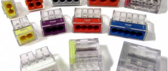
Types of clamps
On the market you can find various models of electrical fittings presented. All devices are divided into two large groups:
- Branch clamps with simultaneous bolt tightening, when both the main cable and the branch are tightened with one screw.
- Fittings with separate piercing of wires.
The use of elements of a particular group depends on the required connection reliability. We must not forget that there are different models of clamps that have their own characteristics. For example, some of them can be dismantled, while others cannot.
Types of punctures for SIP
ZOI
Branch insulated clamps are used when installing lines with voltages up to 1,000 V.
The technique for installing a puncture is well explained in the figure. Dismantling the clamp (if it is necessary to disconnect the branch line) is done quickly. It is enough to loosen the lower head, after which the device can be easily removed.
ZZZRB IEK
This modification of punctures is used when it is necessary to make 2 taps from one point on the line, using a different type of cable. Such clamps make punctures only on the network “thread”, and to attach a branch, its end will have to be cut, as usual.
In the private sector they are used less frequently, since the tightness of the contact point is not high enough. Consequently, when connecting SIP externally, such clamps have limitations in their use. The photo shows the internal structure of the IEK ZZRB puncture (without housing).
Installation method for taps
The design of modern models of outlet terminals allows this operation to be performed in a short time with safety during installation. Thanks to the high quality of materials, the piercing type coupler allows reliable contact without breaking the insulation.
To branch wires, perform the following operations:
- Selecting the appropriate model in accordance with the parameters of the wires being connected.
- Installation of the device on the main line.
- Thread the core into the hole for the branch and fix it with a bolt.
- Gradually tighten the tightening bolt until the head breaks off; this operation is carried out using a torque wrench.
When choosing the right model, you need to study the labeling of the device. It indicates the permissible cross-sections of the cores and the size of the bolt head for the corresponding key. The most commonly used keys are 13 mm in size.
Design of cable piercings
- Frame. The specific operation of the puncture requires its increased strength and resistance to atmospheric factors. Therefore, reinforced polymers or duralumin are used for its manufacture.
- Connecting plates. The peculiarity of their design is in the teeth, which pierce the cable insulation, providing electrical contact.
- The bolts are tight. Depending on the modification of the puncture, 1 - 2 pieces. Heads are shear-type, that is, this fastener is intended for one-time use.
- Caps. Once installed in place, they completely cover the ends of the SIP, which may stick out from the outlet clamps. This ensures the tightness of the connections.
What are the benefits of using punctures?
The technology of installation work is simplified, since there is no need to cut the SIP cable. Reliable, sealed electrical contact. Possibility of connecting a branch to a line without removing voltage from it
It is important if you consider how much time, for example, a summer resident needs to spend to find a local electrician, and even to persuade him to turn off the power to the network.
Bare Wire Clamp
There are 2 main design types of such clamps - intended for insulated and “bare”, that is, cables without insulation. The latter are usually used in main power lines.
If it is necessary to make a branch from the main line, then there is no need for teeth to pierce the insulation. In this case, it is advisable to use a specialized clamp, in which a die without teeth is designed for the main side, while a standard design with teeth is used for the branch side. Of course, it is impossible to install such a system without de-energizing the line.
Purpose of branch insulated cable clamp
The very name of this device very accurately describes the purpose of its use. It clamps the wires, makes physical contact between them and transfers electricity from the carrier to the branch. Moreover, these are not necessarily wires without insulation.
Self-installation
Note! In fact, such a clamp allows even a non-professional to connect to the SIP (not recommended for security reasons). A reliable sealed connection is created that can serve for a long time, and most importantly, safely, in the open air, even under adverse weather street conditions.