general information
Beginner users often wonder what programming logic controllers is. In fact, the programming language of these devices is identical to the operating logic of conventional relays. Therefore, specialists who have previously worked with relay circuits will easily understand the creation of programs for PLCs.
Signal wiring and standard programming development may vary between brands and models of PLCs, but in general terms they will still have a similar set of features and features. Therefore, we can consider general principles.
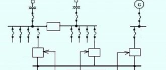
First you need to understand the device itself:
- a simple industrial logic controller on the front includes 2 screw terminals L1 and L2, which are responsible for connecting the internal circuits of the device;
- On the left there are 6 screw terminals, which are necessary for connecting input devices. They represent 6 input channels;
- An opto-isolator is located in the housing to provide an electrically isolated signal to the PC circuit when communication is established between the input terminal and the common terminal. The LED at the input displays the situation, which of the inputs is currently energized;
- The output signals are obtained by the controller circuitry by activating the switching device. This allows you to link a source terminal to a user-labeled Y output.
Thus, PLC programming is based on determining which outputs are energized and what input conditions are present. All programs are developed using a PC, which is connected to the controller's programming port.
Special systems are used to program industrial controllers. There are 2 possible options for this:
- The PLC manufacturer offers its own software environment, which is implemented to work from a specific developer. They are distributed both paid and free, depending on the company and model;
- Software development companies create custom programming systems for PLCs from different manufacturers.
Project composition
We have already briefly mentioned the composition of the system tree. Its creation comes from top to bottom. Controllers are added, built-in modules or communication protocols assigned to specific ports are added, and remote I/O modules are added to them. Modules have their own set of channels. An input/output channel is a set of typical parameters: value, timestamp, polling status. The composition of modules and channel types are predefined by the library developer, but the user can create his own types of modules and channels, including those with built-in signal processing. For example, in a Modbus device, it can divide the address space into a set of modules and channels that corresponds to the physical structure of the device. Controllers, modules and channels of the system tree can belong not only to system programs (drivers) included in a specific executive system, but also to any user programs created for a specific project, or libraries.
The object tree hierarchy consists of objects, tags, and parameters. Objects and tags, just like the system tree elements listed above, can own resources: programs, windows, messages and message logs. In contrast, parameters are atomic project elements that cannot include anything and do not have their own programs or windows. The creation of a parameter type is carried out in a special dialog by selecting from a simple, library or complex (array, structure) data type (Fig. 5).
Rice. 5. Creating a parameter
Siemens programming
Siemens PLC programming may be needed in the following cases:
- occurs in combination with an automation cabinet; it is used to control various automation systems of different purposes and types;
- creating a user interface for devices with displays or simultaneously connected to the operator panel;
- development of programs for processing, archiving and storage, as well as outputting final readings with internal calculations of the PLC itself and from external devices;
- to organize the interaction of the controller with SCADA format systems;
- implementation as part of large-scale automation systems, where several PLCs are connected to the circuit at once;
- implementation of functionality for interaction in special Slave and Master modes with industrial equipment via communication protocols.
Programming of Siemens controllers is carried out in certain environments. One of them is TIA Portal, which is designed for organizing automation systems of various levels of complexity and includes a certain set of software components: Simatic Step 7, WinCC, PLCSIM. Functional:
- development of configuration and debugging of system components;
- creation and adjustment of communication networks;
- software development for controllers;
- organization of Simatic operator panels and implementation of HMI (human-machine interface).
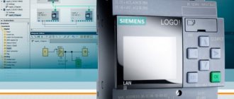
For example, programming of Siemens Logo controllers is carried out, as in the classical general case, after installation and configuration of the device. In this case, in simple words, the process is the input of a switching circuit. Let's list the main stages:
- first, using the standard diagram from the manual, you should understand the location of the connecting elements: inputs and outputs;
- Next you need to understand the blocks and their numbers. Blocks are functions that are responsible for converting input data into output information. Therefore, it is necessary to connect the connecting elements by selecting the required connection from the Co menu. The simplest blocks are logical operations. When a block is inserted into a program, the first one is assigned a specific number, which is subsequently used to display connections between blocks;
- The creation of a circuit occurs by connecting blocks with connecting elements. The process itself begins with an output, which is either a relay or a load, due to which control occurs. At this stage, you need to connect switches S1-S3 to the screw terminals;
- After designing the circuit, it is necessary to enter and launch the program. To do this, the Siemens Logo PLC is connected to the network and the power is turned on. Then the logic controller switches to programming mode, where the desired program is organized based on the previous circuit.
Integrated Environment
The integrated environment MasterPLC Designer (Fig. 3) is implemented taking into account many years of experience in operating MasterSCADA, the shell of which is based on two “pillars”: the object approach with the separation of the physical implementation of the system and the abstract model of the object and the principle of building an “all in one” environment, when for each of a project element, the editors or properties it needs are opened on tabs.
Rice. 3. Integrated environment MasterPLC Designer
Rice. 4. a) System tree; b) Object tree
The structure of the MasterPLC Designer integrated environment remains the same: it is the organization of the project in the form of two object hierarchies: the system tree (Fig. 4a) and the object tree (Fig. 4b). The system tree contains controllers, the communication protocols and services they support, connected modules and their signals. Since programs can be developed directly for the controller and for any of its built-in or external modules, the project can get by with just one system tree. However, it is more correct to use this opportunity only for primary signal processing, specific to this type of equipment, and to develop the monitoring and control logic in a device-independent object tree, which allows you to change the types and composition of equipment at any time without reworking the project. With this approach, you can develop the entire project without reference to the hardware, and only then include its description in the system tree and establish connections between the two hierarchies. In addition to tradition, the project included a tree of connected libraries, which increased the convenience of working with them and made it possible to create project libraries in the same form as the project itself. Project development consists of creating hierarchies, connections between their elements, processing programs, messages and windows (for controllers with local or web visualization). All actions are performed mainly using the “drag and drop” method. For ease of work and establishing connections, any branch of the tree can be opened in a separate window.
“Legend” panels (for working with open editor program elements) and property tables of the selected element also appeared in the program window (Fig. 3). The user can flexibly control the appearance of the development environment: any of the panels can be disabled if not needed using a button located in the program menu bar, and the contents of each panel can be individually scaled for ease of use. Detailed help with the choice of one of the potentially possible topics for a given context from the menu allows the user to clarify any ambiguities “on the spot.”
The experience of communicating with users taught InSAT specialists the diversity of their needs and level of training. Users should be able to tailor the design presentation to their individual needs. Filters serve these purposes, allowing you to remove unnecessary details from the project (Fig. 4b). Along with predefined filters, it is possible to create and save your own, of any complexity, with selection by names, properties, relationships, custom labels, etc. For example, you can leave only all water temperatures from the entire project. Of course, in this case it is more convenient to use a tabular representation of the list of parameters in alphabetical order, to switch to which there is a button in the title line of each tree.
Aries PLC Programming
Aries PLC programming is carried out in IEC 61131-3 languages. Among them, IL, FBD, LD, SFC, ST are used. As mentioned above, for this, environments from the manufacturer (the most suitable option) or third-party software are used. If we are talking about Aries products, then the choice falls on CoDeSys.
The specified programming environment for Aries controllers helps to design a suitable program, as well as debug it and load it into the PLC. To use CoDeSys, the user must take care of the runtime environment provided by the manufacturer or created by the developer himself.
In addition, programming of Aries controllers can be done using the MasterSCADA enterprise dispatch tool, which can act as a suitable environment for the development and implementation of the desired program. The advantage of this option is the ability to combine a whole variety of PLCs that operate on different systems.
HMI - visualization “on board” and in the clouds
New times mean new possibilities for controller processors and programs. It has now become the norm that the controller has a built-in web server. Technologically, this opportunity is provided by modern operating systems installed on controllers, primarily Linux. However, few controllers have the technological prerequisites that lead to the appearance of full-fledged graphics at the level of modern SCADA systems. MasterPLC Designer implements a full-fledged editor of fully vector-based SVG HTML pages, complete with a general industrial library of design objects such as valves, pumps, etc., as well as a number of industry-specific libraries. These objects, along with the monitoring and control logic implemented in the ST program, are also displayed in the form of animated 3D symbols and control windows (Fig. 8).
Rice. 8. Libraries of animated objects
The editor's capabilities are not limited to the use of ready-made objects. The user can create a new symbol from basic primitives, any property of which can be dynamized by project parameters. At the same time, layout is provided using any types of panels to organize the desired arrangement of elements, and the finished mnemonic diagram has the degree of adaptation to the screen size that was laid down by the project developer. For example, a “flexible” (that is, stretched to fit the size of the client screen) layout may contain elements with a limited minimum size (text, images, etc.). As a result, the same mnemonic diagram (Fig. 9) can be equally successfully displayed on the built-in controller panel, a monitor connected directly to it, or on a client device (computer, tablet, smartphone) connected via the Internet. Examples of such mnemonic diagrams can be seen on the website www.sky-monitor.ru.
Rice. 9. Mnemonic diagram of the pumping station
Delta PLC
Delta PLC programming is carried out using a special WPLSoft package, which does not require a large amount of personal computer resources. Therefore, it is suitable for use by specialists of various categories and is very simple. There are 3 languages used here: LD, SFC and IL.
The main feature of the process here is the creation of step diagrams, which ultimately make up the overall program. The process is carried out line by line. This factor greatly simplifies software development for PLC Delta.
OPC UA is the basis of cross-platform communications
Widely used controller communication protocols, such as Modbus, have a significant drawback. They do not allow the controller to be accessed over a routed network, such as the Internet. Classic OPC servers installed on a computer located on the same local network do not save the situation either. The client application also cannot access them from the external network without using additional channel-forming software. The solution is to have a server of the cross-platform OPC UA standard directly on board the controller. The OPC UA standard not only provides data transport in heterogeneous IP networks, but also provides data from the controller with its description, which allows you to connect new clients to the controller “on the go”, without transferring configuration files to them. The inclusion of a server in the MasterPLC OPC UA executive system significantly expands the range of possible applications of this product, including its use as server software for collecting and displaying data on any client devices via the Internet.
Schneider Electric
Schneider Electric PLC programming can be performed using one of several environments: EcoStruxure Machine Expert, EcoStruxure Machine Expert HVAC, Unity Pro, Zelio Soft. Creating programs is used for the same purposes as Siemens brand controllers. The following types of automation systems are most often designed to control technological processes:
- ventilation equipment;
- air conditioning systems;
- individual heating points;
- lighting systems;
- control of conveyor lines and machines;
- water treatment;
- Packaging equipment;
- lifting machines and related mechanisms.
Mitsubishi PLC
Mitsubishi PLC programming is organized using the new generation GX Works2 environment. Supports the following languages: IL, LD, SFC, LD, FBD, ST. The environment comes in two types: GX Works2 and GX Works2 FX. The second is for setting up FX series controllers:
Functionality of the programming environment for Mitsubishi PLC:
- parameterization of functional modules;
- use of software libraries and special functional blocks;
- simulation is built into the system for offline verification of configuration and programs;
- a wide range of functions for diagnostics and debugging;
- the ability to restore previous versions of programs and compare them with current ones;
- compatibility with a number of GX Developer projects.
Technological language editors
MasterPLC Designer is built so that new editors can be added at any time without changing anything in the environment itself. This foresight is connected not only with our own plans, but also with the potential prospects for the development of a standard that has long been confined to the four walls of existing languages.
Previously, it was noted what the ST text language editor looks like (Fig. 3), which has all the standard capabilities of such editors (contextual input assistant and keyword coloring, debugger, etc.). But I would still like to draw the reader’s attention to one point. These are lists of program input parameters to the left and output parameters to the right of the editor field itself. This is what the software terminal block mechanism looks like. It allows a developer using a ready-made program to work with it, even if its code is not viewable. But even if it is open, the terminal block mechanism provides an intermediate layer that protects the program from careless intervention, makes it easy to transfer it to the library or take it from there without code correction, and helps to use the finished code without delving into its internal structure. The number of variables in the terminal strip of a large program can be large, so the same filtering tools can be applied to this list as for the main project, with the difference that a tabular representation of the parameters is initially used for the terminal strip.
The functional block diagram editor (Fig. 6) contains a large number of service functions that make it easy to “draw” monitoring and control algorithms. You can drag not only a library block onto the diagram, but also a program in any language, the terminal blocks of which are converted into inputs/outputs of the block on the diagram. Automatic laying of communication lines with the ability to manually adjust them, snapping to a grid when arranging blocks, inscriptions, controlling the visibility of layers, arranging values in debugging mode directly at the inputs/outputs of blocks - this is not a complete list of available service capabilities.
Rice. 6. Function block diagram editor
Separately, it is worth mentioning the mini-map window, which allows you to move the visible area on a compressed image of the entire circuit in the event that it is too large to fit on the screen. This mechanism also works in other graphic editors, for example the SFC language editor (Fig. 7), designed to control the sequence of execution of programs written in other standard languages.
Rice. 7. SFC editor and minimap mechanism