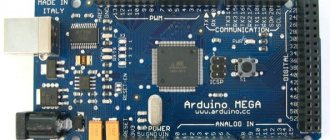
mBlock is an excellent program for teaching robot and Arduino programming skills, based on the famous Scratch environment. It is very easy to download, install and configure, it is completely free and available in Russian for the operating systems Mac OS, Windows, Android and iOS. The ability to sketch visually can help beginners learn programming skills. In this article we have put together useful tips and prepared a short lesson on how to work with mBlock Arduino.
mBlock program
Hello!
The mBlock programming environment was primarily created to work with MakeBlock robotics kits. Today it is actively used both for MakeBlock and for a wide range of Arduino boards. The program is Russified, based on Scratch 2, with its help you can create your own robots of any configuration on Arduino.
Advantages of mBlock:
Yes! My program is the best!
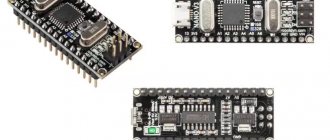
- support for most Arduino boards;
- the ability to use your own blocks with recursion capabilities;
- ease of use of libraries and developments in your own projects;
- ease of creating your own programs;
- You can learn the syntax of a programming language based on mBlock.
Disadvantages of mBLock:
- Sometimes there is instability in interactive mode;
- There is a loss of contact with the microcontroller, which requires the environment to be rebooted.
Visuino
Visuino is a free graphical environment that runs on Arduino-compatible Controllino industrial controllers (PLCs). It makes it possible to create complex automation systems and IoT (Internet of Things) solutions, and this can be done simply by moving and connecting visual blocks. The software environment automatically generates code for industrial controllers.
So what needs to be done. Select components (modules) from the component panel and move them to the design area. Then they need to be connected and properties configured. This is done using the Object Inspector.
The advantages of Visuino include a large set of components for mathematical and logical functions, servos, displays, the Internet, etc.
When the PLC is programmed, the graphical environment prompts the available connection method to the controller. This could be a serial port, Ethernet, Wi-Fi or GSM.
Finally, your project is ready: all controllers are registered, everything works. Now, by clicking on the Arduino logo located on the top panel, you will force Visuino to create codes for the Arduino and open its development environment (Arduino IDE), through which you can already compile the code and load it into the PLC.
Advice. If the installed board does not match your Arduino, you can change it using the Select Board command.
Setting up an environment for working with Arduino
After installing the utility on your PC, you need to make the following settings for further work with Arduino boards:
- Launch the mBlock program.
- Select the item in the main menu board, put a tick next to the required board;
- In the top language menu, select Russian.
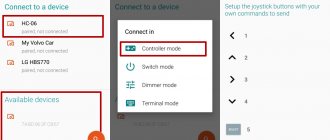
- Then in connect – serial port you need to select the number of the com port to which the microcontroller is connected. If the port number has not been assigned, you need to install the driver. In mBlock you need to select connect – install arduino driver. You can also find drivers on the Internet, download and install them manually.
This completes the basic settings. You can start creating the program.
Ardublock installation
To start working with the program, you need to install it. To do this, let's perform a few simple steps, the algorithm is as follows:
- Download the archive from the ArduBlock website
- Open Arduino IDE/Menu/Arduino/Preferences , there you will find the line Sketchbook location
- Create a folder “tools/ArduBlockTool/tool” inside the “Arduino” folder in the “Sketch location” line and copy the “ardublock-all.jar” archive into the “tool” folder. For example, if the username is “user”, then the path in the Windows environment will be: “C:\Users\user\Documents\Arduino”
- Restart the Arduino IDE and you should see the “ArduBlock” item in the “Tool” menu
When installing on a Mac for the user user, the path will be as follows: “/Users/user/Documents/Arduino/tools/ArduBlockTool/tool/ardublock-all.jar” When installing on Linux: “/home/user/sketchbook/tools/ArduBlockTool/ tool/ardublock-all.jar”
mBlock for Arduino programming
Distinctive features:
- It is possible to connect to a microcontroller and update its firmware. This is done in the top menu in the program. This function greatly simplifies the process - for example, in S4A you have to download special files, open them in the Arduino IDE and load them onto the controller itself. In mBlock everything is much simpler.
- In the top menu you can select the desired board.
- There is a special command box called Robot. It contains various blocks that help read data and control the controller. They can be combined with commands from other boxes.
- It is possible to generate Arduino code and edit it in the Arduino IDE. The code is generated from a virtual script. Thus, you can visually evaluate how a particular command works in a program and study the syntax of the programming language.
- For work, there is a special robot based on Arduino - mBot. It has special training materials and instructions that will be useful for beginners of any age.
The main difference between mBlock is the simplicity and interactivity of programming.
What is Ardublock?
Ardublock is a program or rather an add-on to the Arduino IDE that allows us to create programs and code without having to write code. , that is, using visual means. This has its advantages, because if we know how to program, we will save a lot of time in the debugging process, since we will not forget to write the well-known ";" however, it does not close the code brackets. Programming with Visual Tools - This programming is intended for both beginners and experienced programmers, as well as for users who do not know how to program and want to learn how to do it.
As we already said, Ardublock is more of an add-on than a program itself, since it requires the Arduino IDE to run. So to summarize, we can say that Ardublock is a customization of Arduino IDE to adapt code programming to visual programming.
Ardublock has other advantages besides being a tool for novice programmers. One of its positive aspects is the ability to work with blocks to create projects faster .
Ardublock works visually with blocks and can also work with components. So we can create a block that is wheels, another that is music, and another that is a plate; every time we want to use these blocks we give it a name or simply drag it from one side of the window to the other side of the window.
The functions and capabilities that Ardublock offers us are the same as what the Arduino IDE offers us, that is, we can connect Ardublock to our Arduino board, send the code generated by Ardublock using the blocks, and test our projects quickly and easily. And when we finish the program, the saved information is still the written code, the code that Ardublock created with our blocks .
Description of mBlock program blocks
mBlock programming is simple and intuitive. The “Scripts” palette contains various blocks - elementary commands. With their help you can create a program. Commands need to be dragged onto the workspace to create your project.
How it works using the example of the mBot robot moving back and forth:
How interesting!
- MBot program – name of the program.
- There is a block “Always” (forever) - an endless loop is created in it, within which the written commands are repeated many times until it stops.
- Run forward at speed 100 (not translated into Russian). Allows you to rotate the robot's motors so that it moves at a speed of 100.
- “Wait 1 second” – waiting block. The robot will move forward for 1 second. While moving, the program does nothing and simply waits for the robot to cover a certain distance during this time.
- Run backward at speed 100 – command for the robot to move backward at speed 100.
- Repeat “Wait 1 second” again. The robot moves backwards for 1 second, moving a certain distance.
The cycle will repeat ad infinitum. You can complicate the program by adding blocks for rotating by an angle, moving to a given coordinate, etc.
To create your own program, you should switch to “Arduino mode”. The screen layout will change and not all blocks will be available.
After the program is registered, you need to click the Upload to Arduino button. The program will be loaded into the microcontroller. After loading, Upload Finish will appear on the monitor, and the robot will begin to execute the command.
Programming Arduino using ArduBlock (download)
- Computer Science Lessons
- For teachers
- For computer science teachers
Arduino compatible boards are programmed in the Wiring language, which is very similar in syntax to C. However, in my personal experience, this language is difficult for children aged 11-13 to master, especially if before that the children created programs in LabView by dragging blocks onto the desktop. Many guys who are interested in robotics are well acquainted with the visual programming language Scratch, on the basis of which many solutions for education already exist. Among similar solutions for Arduino, a tool written in Java called ArduBlock has been created.
Yes, someone may say that there is also Scratch for Arduino (s4a) and it is also a very simple graphical environment for Arduino programming. But Scratch does not flash the Arduino, but only controls it via a USB cable. Arduino is computer dependent and cannot work autonomously. When creating your own projects, autonomy is key for Arduino, especially when creating robotic devices.
So, what is ArduBlock? This is a graphical programming environment. Almost completely translated into Russian. But the highlight of ArduBlock is not only this, but also the fact that the ArduBlock program we wrote converts into Arduino IDE code. This program is built into the Arduino IDE programming environment, i.e. it is a plugin! Below is an example of a blinking LED and a converted program in Arduino IDE. All work with the program is very simple and any student can understand it.
As a result of working with the program, you can not only program the Arduino, but also study commands that we do not understand in the text format of the Arduino IDE, but if you are too lazy to write standard commands, you can quickly use the mouse to sketch out a simple program in ArduBlok, and debug it in the Arduino IDE . To install ArduBlok, you need to follow the instructions described below, but you will still have to do some dances with a tambourine, since this plugin does not work in the latest versions of the Arduino IDE. If you don’t want to dance with tambourines, then I suggest you download the archive with the already integrated ArduBlock tool for Arduino IDE 1.6.11. This version does not require installation. You only need to unzip the folder to a convenient location and launch the Arduino IDE. And DO NOT FORGET to install the Java virtual machine, it is necessary for the normal operation of this plugin, installation takes 1-2 minutes.
Download Arduino IDE 1.6.11 with ArduBlock
Instructions for dancing with a tambourine: First, download and install the Arduino IDE from the official Arduino website and understand the settings when working with the Arduino UNO board. How to do this is described on the same website or on Ampere, or watch it on YouTube. Well, when all this is figured out, you need to download ArduBlok from the official website, here is the link. Then, rename the downloaded file to ardublock-all and in the “documents” folder. We create the following folders: Arduino > tools > ArduBlockTool > tool and put the downloaded and renamed file into the last one. ArduBlok works on all operating systems, even on Linux, I personally tested it on XP, Win7, Win8, all examples are for Win7. The installation of the program is the same for all systems.
In order to work in ArduBlok, you need to run the Arduino IDE. Then we go to the Tools tab and there we find the ArduBlok item, click on it - and here it is, our goal.
Based on the article: https://geektimes.ru/post/258834/ Programming Arduino using ArduBlock using the example of a robot moving along a strip.
Tags: arduino
Please rate the article
3.82 out of 5. (Total votes: 136)
3.1/5 stars (297 votes)
All articles in this section
Moodle. Formulas.Moodle question type. Systems for testing student programs
- Comments VK
- Anonymous comments, G+ or Facebook
comments powered by Disqus
Installing extensions
To expand the functionality, you can install extensions. One of them is AdvancedArduino - it can be used instead of a standard Arduino and provide additional capabilities in Arduino Mode.
These options include:
- Graphic blocks for the min, max, map, pow and other functions needed to convert values.
- Additional graphical commands for working with serial and serial buses
- The names of the blocks correspond to the names of the library functions.
- The use of blocks that allow you to insert arbitrary code fragments in the Wire language.
- Definition of local and global variable parameters of functions of arbitrary type.
You can install the extension like this:
Select the Manage Extensions command
A list of available extensions will be downloaded from the official website, from which you need to search for AdvancedArduino
Click "Download" on the selected item
Everything has loaded!
2Programino development environment
Programino logo
Let's look at the PROGRAMINO development environment. This is a paid development environment, but you can try it for 14 days for free. Programino, like other development environments, however, requires that you have the Arduino IDE installed. When you first start the program, you should specify the path to the executable file arduino.exe in the settings. To do this, go to the settings menu: Options Editor Settings
. A window will appear in which you will need to specify the path to the directory with the Arduino IDE and related libraries. Now we are ready to write programs in Programino.
Initial setup of the Programino environment
The language used in this development environment is the same as in the original Arduino IDE - C. That is, in fact, if you are already writing sketches in the Arduino IDE, then you will not have to learn a new programming language, which is a big advantage of this development environment.
However, in addition to this, this IDE offers such a convenient way of rapid development as code completion. That is, you don’t have to constantly look into the reference book on Arduino commands and methods. You start typing code, and the development environment will prompt you to choose from the available options the one you need. For example, you type “digi” and the IDE gives you options: “digitalRead”, “digitalWrite” and other possible ones.
Code completion function of Programino IDE
Let's write a simple sketch in which we will constantly poll one of the analog pins of the Arduino and output the readings to the serial port.
Try typing the sketch by hand rather than copying and pasting to experience the convenience of Programino code completion.
const int pinA = A5; void setup() { pinMode(pinA, INPUT); Serial.begin(19200); } void loop() { int r = analogRead(pinA); Serial.println(r); delay(100); }
What else interesting does Programino IDE offer? This development environment has several additional useful tools available through the Tools
. For example: notepad, LCD symbol designer, DEC-BIN-HEX converter, serial port terminal, analog plotter and others.
Additional Programino IDE tools
Let's take a closer look at the Analog Plotter
. This tool allows you to visualize what is coming into the COM port from the Arduino.
For the plotter to work in the sketch, you need to enable the serial port at a speed of 19200 kb/sec. Analog data is output to the plotter using the Serial.println() command.
Let's start the analog plotter. Let's press the Connect button to connect to the port to which we have the Arduino connected.
Analog plotter in Programino
This tool can be useful, for example, for displaying readings over time of some analog sensors: temperature, humidity, pressure, illumination and others.
Before writing a sketch into the Arduino memory, you should specify the type of board used and the port to which it is connected through the Hardware
.
Selecting a board in Programino
Selecting a serial port in Programino
To load the sketch into the Arduino memory, click the download icon in the top menu. Programino will download the sketch and in the lower log window will show data about the size of the sketch and the remaining free resources of the Arduino board.
Example program in mBlock
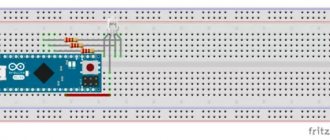
Let's write our first project in the mBlock environment. As an example, we will consider blinking an LED. First, the light emitting diode needs to be connected to the Arduino board. The LED legs should be connected to pins 13 and GND.
Then the program itself is written in mBlock. It looks like this:
Example program on mBlock 3
Arduino and Forever blocks are mandatory. There are also blocks that indicate which pins the LED is connected to. In this case, either high or low voltage is applied to pin 13, causing the diode to light up and then go out.
The essence of the block is simple - the cycle must be repeated endlessly. The program uses delays to pause. The interval is 1 second.
After writing the program, you need to click Upload to Arduino. The program will download to the microcontroller and the LED will start blinking.
What to do and how to write next?
If you are a beginner and are just immersing yourself in the language, it is better to write as it is written. It is considered good practice to have a minimum number, or better yet, the absence of global variables for the entire program: very often a global one can be made local static and hidden from the rest of the code without losing its functionality. Separate and independent parts of the program (poll of buttons, processing values, sending and parsing data, etc.) can be wrapped in a class, placed in a separate file and thus shortened the code of the main program, increasing its readability and structure. But do not forget that the same problem can be solved in an infinite number of ways, and not all of them are optimal. If the program has identical “blocks” that require the same set of variables, it will be much more convenient to wrap them in a class. Moreover, over time, you will accumulate your own set of such mini-libraries and they will be very convenient to use in future work. In my lessons there is a lesson on classes and on writing libraries, but only a small and very basic part of the capabilities of OOP is discussed there. To write powerful and universal tools, study any C++ lessons; after studying my lessons, you will be ready for them and everything will be clear. Also, classes in C++ have such a powerful feature as inheritance: one class can inherit the capabilities of another class. For example, almost all display libraries, as well as Serial and soft Serial, have an “omnivorous” print() method, which prints variables of any type, can show numbers in different representations, format the output of float numbers, and so on. The interesting point here is that all these capabilities are implemented in the standard Print class, which lies among the other files in the Arduino IDE core, and all other libraries simply inherit all output capabilities from it. In fact, only write() should be implemented in the display/Serial library, and absolutely all other output versatility is provided by “collaboration” with the Print class. In this series of lessons, we will not discuss inheritance and other OOP tools, because it is unlikely to even be useful to you and is already perfectly covered in any book or any C++ lessons on the Internet (I like the lessons on the Ravesli website). Wrapping it in a class is not a panacea: if a piece of program does not involve creating and using multiple instances of itself, then it can simply be placed in a separate file, as a set of functions and variables. In this case, global variables should be made static so that they are “not visible” from other program files. Why and how to work with this? When creating large projects (and in general), you should adhere to the concept of “data separately, code separately,” that is, there should not be global variables that are in the definition area of the entire program, at least their number should be reduced to a minimum. Global variables can be hidden inside a file, which is ensured by the static keyword (variables must be declared in the .c or .cpp file!), and their values can be shared with the rest of the program code and a new value can be set using separate functions. As an example of a very large project made with a clear file structure and without the use of OOP and classes - GRBL firmware. Also, most global variables can be hidden inside functions where they are needed (that is, if they are needed only inside a specific function), again using static. We talked about this at the very beginning, in the lesson about data types.
Example 1
Let's look at an example of turning a terrible “vinigret” code with a bunch of global variables and a mess in the main loop into a clear program with separate independent subroutines. In this example, we have two buttons connected (on pins D2 and D3) and an LED (we use an onboard one on pin D13). Let's write a program that will blink an LED and asynchronously poll buttons with software contact debouncing. Using the buttons you can change the blinking frequency of the LED. There is no point in commenting on the code in detail, because we have discussed all the constructs used more than once in the series of lessons.
Bad code
// pins const byte btn1 = 2; const byte btn2 = 3; const byte led = 13; // change step const int step = 50; // button debounce timers uint32_t btn1Tmr; uint32_t btn2Tmr; // button polling flags bool btn1Flag; bool btn2Flag; // variables for the LED uint32_t ledTmr; int ledPeriod = 1000; // initial period 1 second bool ledState = false; void setup () { // set up pins pinMode(btn1, INPUT_PULLUP); pinMode(btn2, INPUT_PULLUP); pinMode(led, OUTPUT); } void loop() { // LED timer if (millis() - ledTmr >= ledPeriod) { ledTmr = millis(); ledState = !ledState; digitalWrite(led, ledState); } // polling the first button with a debounce of 100ms bool btn1State = digitalRead(btn1); if (!btn1State && !btn1Flag && millis() - btn1Tmr >= 100) { btn1Flag = true; btn1Tmr = millis(); ledPeriod += step; // increase the period } if (btn1State && btn1Flag && millis() - btn1Tmr >= 100) { btn1Flag = false; btn1Tmr = millis(); } // polling the second button with a debounce of 100ms bool btn2State = digitalRead(btn2); if (!btn2State && !btn2Flag && millis() - btn2Tmr >= 100) { btn2Flag = true; btn2Tmr = millis(); ledPeriod -= step; // decrease the period } if (btn2State && btn2Flag && millis() - btn2Tmr >= 100) { btn2Flag = false; btn2Tmr = millis(); } }
Adding additional buttons or additional LED functionality to the program will lead to great confusion and an increase in the amount of code, which will be much more difficult to understand. Let's wrap the button processing in a class, because we already have two identical buttons, and in the future we can add more to the program. Let’s immediately move the class into a separate file and format it as a library:
button.h
// button class #pragma once #include #define _BTN_DEB_TIME 100 // anti-bounce timeout class Button { public: Button (byte pin) : _pin(pin) { pinMode(_pin, INPUT_PULLUP); } bool click() { bool btnState = digitalRead(_pin); if (!btnState && !_flag && millis() - _tmr >= _BTN_DEB_TIME) { _flag = true; _tmr = millis(); return true; } if (btnState && _flag && millis() - _tmr >= _BTN_DEB_TIME) { _flag = false; _tmr = millis(); } return false; } private: const byte _pin; uint32_t_tmr; bool_flag; };
The button handler now works as follows: returns true if the corresponding button was clicked. In the main program, we will place the click() method in the condition and change the period of the LED based on it. I plan that in this project I will have only one blinking LED, and I will not wrap it in a class: I will simply put the functions in a file (for an example of implementing a project in this way).
led.h
// flashing LED #pragma once #include void LEDinit(byte pin, int period); void LEDblink(); void LEDadjust(int val);
led.cpp
#include "led.h" // static variables will be "visible" only in this file static int _period; static byte_pin; static uint32_t_tmr; static bool_flag; void LEDinit(byte pin, int period) { _pin = pin; _period = period; pinMode(_pin, OUTPUT); } void LEDblink() { if (millis() - _tmr >= _period) { _tmr = millis(); _flag = !_flag; digitalWrite(_pin, _flag); } } void LEDadjust(int val) { _period += val; }
Please note that inside the files I used variables with the same names, but I made these variables either static or hidden in a class. This is very convenient because they will never intersect with each other and you can use the same ones to denote variables with a similar meaning. Thus, we received two separate modules, two separate subroutines that can be interacted with from the main program. I changed the blinking period of the LED using the LEDadjust() function, which accepts an amendment to the current value. The initial “current” value is set during initialization in LEDinit(). Well, let's put our libraries next to the main program file, connect them to the code and see what our project now looks like: // change step const int step = 50; // LED library #include "led.h" // button library #include "button.h" Button btn1(2); Button btn2(3); void setup() { // specify the pin and start period LEDinit(13, 1000); } void loop() { LEDblink(); // blink if (btn1.click()) LEDadjust(step); if (btn2.click()) LEDadjust(-step); }
Well, that's a completely different matter! Now we have the flies separately from the cutlets and we can carefully refine both modules independently of each other. By the way, what about the code size? The very first example takes up 1306 bytes of Flash and 26 bytes of RAM, and the new one... 1216 bytes of Flash and 29 bytes of RAM. The volume of code (number of lines) has increased, but its weight has decreased by 100 bytes! The fact is that we have two instances of the button, which are polled in essentially the same way. We made polling as a class method, and the compiler did not duplicate it on different buttons. Let's develop the program a little and add another button with which you can turn the LED on and off, for which we will add such an opportunity to its library. And to the button class we will add a method that will return true pulsed when the button is held down, in order to change the frequency by holding the button down accordingly. Let's add a tricky condition to the button handler that will return true by timer if the button is held, that is, it has not yet been released after being pressed. Thus, it will be possible to change the value once by “clicking”, or hold it down and it will change in steps, as in any Chinese watch.
button.h
// button class #pragma once #include #define _BTN_DEB_TIME 100 // anti-bounce timeout #define _BTN_HOLD_TIME 400 // pulse hold timeout class Button { public: Button (byte pin) : _pin(pin) { pinMode(_pin, INPUT_PULLUP); } bool click() { bool btnState = digitalRead(_pin); if (!btnState && !_flag && millis() - _tmr >= _BTN_DEB_TIME) { _flag = true; _tmr = millis(); return true; } if (!btnState && _flag && millis() - _tmr >= _BTN_HOLD_TIME) { _tmr = millis(); return true; } if (btnState && _flag && millis() - _tmr >= _BTN_DEB_TIME) { _flag = false; _tmr = millis(); } return false; } private: const byte _pin; uint32_t_tmr; bool_flag; };
You can implement turning the LED on and off as a “status” of the entire software module using a flag (the main blink() method will be executed using it), add it to the variables. There are several ways to pull the flag:
- Make a toggle() function that will simply invert the flag
- Create functions enable() and disable() that will turn the flag on and off respectively
- Make a setup and read the current state
And so on. Let's focus on manual installation and status reading as a universal option.
led.h
// flashing LED #pragma once #include void LEDinit(byte pin, int period); void LEDblink(); void LEDadjust(int val); void LEDsetState(bool state); bool LEDgetState();
led.cpp
#include "led.h" // static variables will be "visible" only in this file static int _period; static byte_pin; static uint32_t_tmr; static bool_flag; static bool _state = true; void LEDinit(byte pin, int period) { _pin = pin; _period = period; pinMode(_pin, OUTPUT); } void LEDblink() { if (_state && millis() - _tmr >= _period) { _tmr = millis(); _flag = !_flag; digitalWrite(_pin, _flag); } } void LEDadjust(int val) { _period += val; } void LEDsetState(bool state) { _state = state; if (_state) digitalWrite(_pin, 0); } bool LEDgetState() { return _state; }
Let's add another button to pin D4 to the main program and switch the state of the LED: // change step const int step = 50; // LED library #include "led.h" // button library #include "button.h" Button btn1(2); Button btn2(3); Button btn3(4); void setup() { // specify the pin and start period LEDinit(13, 1000); } void loop() { LEDblink(); // blink if (btn1.click()) LEDadjust(step); if (btn2.click()) LEDadjust(-step); if (btn3.click()) LEDsetState(!LEDgetState()); }
Now the buttons on pins 2 and 3 by clicking increase and decrease the blinking frequency of the LED, when held, the frequency changes automatically with the same step and the period configured in button.h, and by clicking on the button on pin 4 we can turn on or off the blinking process. Thus, we have already obtained some developments that can be inserted entirely, directly as a file, into another project and used. This is the beauty of OOP and, in general, the concept of separating data from code and eliminating global variables for the entire program.
Example 2
Next, let's remember the example with a weather station from the lesson on how to write a sketch and try to “comb it” a little: wrap everything in classes, scatter it into separate files and separate the data from each other. Although we will still make a class for a millis timer, because there it is used in three places, and with further development, more timers may be needed. The original project takes up 10078 bytes of Flash and 511 RAM.
Weather station
// SETTINGS #define ONE_WIRE_BUS 2 // pin ds18b20 // LIBRARIES #include #include #include #include #include // OBJECTS AND VARIABLES // address can be 0x27 or 0x3f LiquidCrystal_I2C lcd(0x3f, 16, 2); // Set up the display RTC_DS3231 rtc; OneWire oneWire(ONE_WIRE_BUS); DallasTemperature sensors(&oneWire); uint32_t myTimer1, myTimer2, myTimer3; boolean LEDflag = false; float tempSum = 0, temp; byte tempCounter; void setup() { Serial.begin(9600); // for debugging pinMode(13, 1); // display lcd.init(); lcd.backlight(); // Turn on the display backlight // thermometer sensors.begin(); sensors.setWaitForConversion(false); // asynchronous data reception // clock rtc.begin(); // setting the time equal to the compilation time if (rtc.lostPower()) { rtc.adjust(DateTime(F(__DATE__), F(__TIME__))); } } void loop() { // 2 times per second if (millis() - myTimer1 >= 500) { myTimer1 = millis(); // reset timer toggleLED(); } // 5 times per second if (millis() - myTimer2 >= 200) { myTimer2 = millis(); // reset timer getTemp(); } // every second if (millis() - myTimer3 >= 1000) { myTimer3 = millis(); // reset timer redrawDisplay(); } } void toggleLED() { digitalWrite(13, LEDflag); // on/off LEDflag = !LEDflag; // invert the flag } void getTemp() { // sum the temperature into a common variable tempSum += sensors.getTempCByIndex(0); sensors.requestTemperatures(); // measurement counter tempCounter++; if (tempCounter >= 5) { // if greater than 5 tempCounter = 0; // reset temp = tempSum / 5; // arithmetic mean tempSum = 0; // reset } } void redrawDisplay() { // TIME DateTime now = rtc.now(); // get the time lcd.setCursor(0, 0); // cursor at 0,0 lcd.print(now.hour()); // clock lcd.print(':'); // the first zero is for beauty if (now.minute() < 10) lcd.print(0); lcd.print(now.minute()); lcd.print(':'); // the first zero is for beauty if (now.second() < 10) lcd.print(0); lcd.print(now.second()); // TEMP lcd.setCursor(11, 0); // cursor at 11.0 lcd.print("Temp:"); lcd.setCursor(11, 1); // cursor at 11.1 lcd.print(temp); // DATE lcd.setCursor(0, 1); // cursor at 0.1 // first zero for beauty if (now.day() < 10) lcd.print(0); lcd.print(now.day()); lcd.print('.'); // the first zero is for beauty if (now.month() < 10) lcd.print(0); lcd.print(now.month()); lcd.print('.'); lcd.print(now.year()); }
So, I wrapped everything in classes, and made the objects of the connected external libraries static so that they were “not visible” from the main program and could not be mixed with anything. I didn’t touch the display, all the output to it remained as it was, the display itself is “connected” in the main sketch.
Main sketch
// LIBRARIES #include #include LiquidCrystal_I2C lcd(0x27, 16, 2); // Set up the display #include "led.h" Led led(13); // LED on pin 13 #include “timer.h” Timer ledTimer(500); // LED timer for 500 ms Timer tempTimer(800); // sensor timer 800 ms Timer displayTimer(1000); // display for 1 second #include “realTime.h” RealTime rtc; #include "temperature.h" Temperature dallas; void setup() { Serial.begin(9600); // for debugging dallas.begin(); rtc.begin(); lcd.init(); lcd.backlight(); // Turn on the display backlight } void loop() { if (ledTimer.ready()) led.toggle(); if (tempTimer.ready()) dallas.filter(); if (displayTimer.ready()) redrawDisplay(); } void redrawDisplay() { // TIME rtc.update(); // get the time lcd.setCursor(0, 0); // cursor at 0,0 lcd.print(rtc.hour()); // clock lcd.print(':'); // first zero for beauty if (rtc.minute() < 10) lcd.print(0); lcd.print(rtc.minute()); lcd.print(':'); // the first zero is for beauty if (rtc.second() < 10) lcd.print(0); lcd.print(rtc.second()); // TEMP lcd.setCursor(11, 0); // cursor at 11.0 lcd.print("Temp:"); lcd.setCursor(11, 1); // cursor at 11.1 lcd.print(dallas.get()); // DATE lcd.setCursor(0, 1); // cursor at 0.1 // first zero for beauty if (rtc.day() < 10) lcd.print(0); lcd.print(rtc.day()); lcd.print('.'); // the first zero is for beauty if (rtc.month() < 10) lcd.print(0); lcd.print(rtc.month()); lcd.print('.'); lcd.print(rtc.year()); }
led.h
#pragma once #include // LED class class Led { public: // create with pin specified Led (byte pin) { _pin = pin; pinMode(_pin, OUTPUT); } // toggle state void toggle() { _state = !_state; digitalWrite(_pin, _state); } private: byte_pin; bool_state; };
timer.h
#pragma once #include // millis timer class class Timer { public: // create with period Timer (int period) { _period = period; } // returns true when the period is triggered bool ready() { if (millis() - _tmr >= _period) { _tmr = millis(); return true; } return false; } private: uint32_t_tmr; int_period; };
realTime.h
#pragma once #include #include #include class RealTime { public: void begin(); void update(); byte hour(); byte minute(); byte second(); byte day(); byte month(); int year(); private: byte _h, _m, _s; byte _day, _month; int_year; };
realTime.cpp
#include "realTime.h" static RTC_DS3231 rtc; void RealTime::begin() { rtc.begin(); // setting the time equal to the compilation time if (rtc.lostPower()) { rtc.adjust(DateTime(F(__DATE__), F(__TIME__))); } } void RealTime::update() { DateTime now = rtc.now(); _h = now.hour(); _m = now.minute(); _s = now.second(); _day = now.day(); _month = now.month(); _year = now.year(); } byte RealTime::hour() { return _h; } byte RealTime::minute() { return _m; } byte RealTime::second() { return _s; } byte RealTime::day() { return _day; } byte RealTime::month() { return _month; } int RealTime::year() { return _year; }
temperature.h
#pragma once // sensor polling and filtering class #define ONE_WIRE_BUS 2 // ds18b20 pin #include #include #include class Temperature { public: void begin(); void filter(); float get(); private: float tempSum = 0, temp = 0; byte tempCounter = 0; };
temperature.cpp
#include "temperature.h" static OneWire oneWire(ONE_WIRE_BUS); static DallasTemperature sensors(&oneWire); void Temperature::begin() { // thermometer sensors.begin(); sensors.setWaitForConversion(false); // asynchronous data acquisition } void Temperature::filter() { // sum the temperature into a common variable tempSum += sensors.getTempCByIndex(0); sensors.requestTemperatures(); // measurement counter tempCounter++; if (tempCounter >= 5) { // if greater than 5 tempCounter = 0; // reset temp = tempSum / 5; // arithmetic mean tempSum = 0; // reset } } float Temperature::get() { return temp; }
Yes, there is a lot more code, we wrote it longer, it now takes up 10322 and 539 bytes of Flash and RAM, respectively (240 and 28 bytes more), but our
sketch has turned into a full-fledged project : you can work on finalizing each “module” separately and not be afraid to interfere with the main code, you can very conveniently replace the sensor or real-time clock with any other, and so on! It will be pleasant and understandable to work with such code even after a few years, when everything is forgotten, and it will be easier for another person to understand it. This is the main essence of this approach to writing large programs.
mBlock 5.0.1
Version 5.0.1 with a new design and better graphics than the previous version, as well as with a new version of Scratch, takes a good place in the Arduino software market. But since it is still at the development stage, we can assume (or even say with confidence) that there will be other upgrades to mBlock 5.
mBlock 5.0.1
Comparison of versions
mBlock 5 has several differences from mBlock 3:
- The graphics have become better
- All blocks have been translated into Russian
- It is possible to transfer the mBlock program to Python.
- New design that looks more attractive than the previous one
Ardublock Alternatives
Although Ardublock may seem like something new and unique to Arduino, the truth is that it is not the only program or tool that we have to follow for visual programming. There are several tools that focus on visual programming to the point that all Ardublock alternatives are unique programs and not extensions or plugins for the Arduino IDE.
The first of these alternatives is called Minibloq. Minibloq is a complete program focused on visual programming. Therefore, its screen is divided into three parts: a part with the blocks that need to be created, another part where we will move the blocks that we want to use in the program, and a third part that will show the code that we will create, for more advanced users. The miniblock can be obtained through this link.
The second tool is called Scratch for Arduino . This tool tries to adapt the children's Scratch program to any level and create programs with the same philosophy. Scratch for Arduino is a full-fledged program, a fork of Scratch, so to speak.
The third of the tools is not yet well understood, but it is a promising tool in visual programming tools. This tool is called Modkit , a tool that was born on Kickstarter, but is gradually evolving and developing well. Unlike other programs, it may focus more on beginner users than advanced ones. . Finally, another alternative to Ardublock could be the traditional use of the Arduino IDE, an alternative that is not visual and will only be accessible to the most experienced programmers.
3Development environment B4R (Basic for Arduino)
B4R logo
Another interesting alternative to the Arduino IDE is B4R, or “Basic for Arduino”. This development environment is unique in that it uses Basic rather than C. It also supports code completion functionality. Moreover, it is completely free.
When starting for the first time, the B4R environment also requires you to specify the path to the directory with the Arduino IDE and, if necessary, additional non-standard libraries and common modules. These settings can be configured later through the Tools Configure Paths
.
B4R environment settings
And also select the board: Tools Board Selector
:
Selecting an Arduino board in B4R
Let's write a sketch like this and at the same time get a little closer to the development environment.
B4R IDE main window
In the central part there is a field for editing the code. On the right is the tab area and the tabs themselves: available libraries, sketch modules, journal and search. In the photo above, the tab with the magazine is open. It can be seen that messages that are specified in the program using the Log() command are displayed here. In this development environment, you can set breakpoints, which is very useful during debugging, and also use bookmarks for faster code navigation.
You won't be able to start programming in this development environment right away, because... it uses a different, more object-oriented language than the classic Arduino IDE, with a different syntax. However, the convenience of this environment and the presence of good guidance from the developers completely compensate for these shortcomings.
Installing and launching the FLprog development environment
Go to the official FLprog website and download the program. There is a forum on the site, if you have any technical difficulties, you can ask for help.
Next comes the standard installation of software packages.
Let's launch:
I suggest we choose a project for SCADA or for a controller. First, let's look at the project for the controller:
Here, in principle, there are two programming languages according to the IEC standard - ladder diagrams, ladder diagram (LD), or graphic blocks (FBD). Some are comfortable, some are used to it. I choose FBD.
On the left side there is a project tree, in the middle there is a canvas, on the right side there are properties and all the necessary elements.
Something very reminiscent of this (CoDeSyS 3.5 shell)
Or this (Owen Logic PR110 shell)
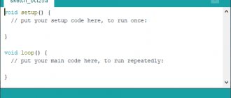
Arduino.ru
The Arduino development environment consists of a built-in text editor for program code, a message area, a text output window (console), a toolbar with buttons for frequently used commands, and several menus. The development environment is connected to the Arduino hardware to download programs and communicate.
Download
The latest version can be found at this link https://www.arduino.cc/en/Main/Software
Useful links:
- Getting started in Windows
- Installing Arduino IDE on Ubuntu Linux
A program written in the Arduino environment is called a sketch. The sketch is written in a text editor that has cut/paste and search/replace text tools. When saving and exporting a project, explanations appear in the message area, and errors may also be displayed. The text output window (console) shows Arduino messages, including full error reports and other information. The toolbar buttons allow you to check and record the program, create, open and save a sketch, and open serial bus monitoring:
Verify/Compile Checking program code for errors, compilation.
Stop Stops Serial monitor or dims other buttons.
New Create a new sketch.
Open Opens the access menu to all sketches in the notebook. Opens by clicking in the current window.
Note: Due to a bug in Java, this menu cannot scroll; If you need to open a sketch from this list, go to the File | Sketchbook.
Save Saves the sketch.
Upload to I/O Board Compiles program code and uploads it to the Arduino device. The download description is below.
Serial Monitor Opens serial bus monitoring (Serial monitor).
Additional commands are grouped into five menus: File, Edit, Sketch, Tools, Help. Menu availability depends on the job currently in progress.
Edit
- Copy for Discourse Copies the sketch code suitable for posting on the forum to the clipboard with syntax highlighting.
- Copy as HTML Copies the sketch code to the clipboard as HTML code for placement on web pages.
Sketch
- Verify/Compile Checking the sketch for errors.
- Import Library Adds a library to the current sketch by inserting an #include directive into the sketch's code. Detailed information in the description of libraries below (Libraries).
- Show Sketch Folder Opens the folder containing the sketch file on the desktop.
- Add File... Adds a file to the sketch (the file will be copied from the current location). The new file appears in a new tab in the sketch window. The file can be deleted from the sketch using the bookmarks menu.
Tools
- Auto Format This option optimizes the code, for example, lining up the opening and closing brackets vertically and placing a statement between them.
- Board Select the platform to use. A list describing the platforms is given below.
- Serial Port The menu contains a list of serial data transfer devices (real and virtual) on the computer. The list is updated automatically every time you open the Tools menu.
- Burn Bootloader The items in this menu allow you to burn the Bootloader to the microcontroller on the Arduino platform. This action is not required for current work with Arduino, but will be useful if you have a new ATmega (without a bootloader). Before recording, it is recommended to check that the correct platform is selected from the menu. When using AVR ISP, you must select the port corresponding to the programmer from the Serial Port menu.
Sketchbook
The Arduino environment uses the notepad principle: a standard place for storing programs (sketches). Sketchbooks can be opened via the File > Sketchbook menu or the Open button on the toolbar. When you first launch the Arduino program, a directory for the notepad is automatically created. The notepad location is changed through the Preferences dialog box.
Bookmarks, Files and Compilation
Allows you to work with several sketch files (each opens in a separate tab). Code files can be standard Arduino files (no extension), C files (*.c extension), C++ files (*.cpp) or head files (.h).
Uploading a Sketch to Arduino
Before uploading the sketch, you need to set the necessary parameters in the menu Tools> Board and Tools> Serial Port . The platforms are described further in the text. On a Mac OS, the serial port may be designated as dev/tty.usbserial-1B1 (for a USB card) or /dev/tty.USA19QW1b1P1.1 (for a serial card connected via a Keyspan USB-to-Serial adapter). In Windows OS, ports can be designated as COM1 or COM2 (for a serial bus card) or COM4, COM5, COM7 and higher (for a USB card). The USB port is identified in the USB Serial Bus field in Windows Device Manager. In Linux OS, ports can be designated as /dev/ttyUSB0, /dev/ttyUSB1.
After selecting the port and platform, you must click the upload button on the toolbar or select the File > Upload to I/O Board menu item. Modern Arduino platforms reboot automatically before booting. On older platforms, you must hit the reboot button. On most boards the RX and TX LEDs will flash during the process. The Arduino development environment will display a message indicating that the download is complete or that there are errors.
When loading a sketch, you use the Arduino Bootloader, a small program that is loaded into the microcontroller on the board. It allows you to download program code without using additional hardware. The Bootloader is active for several seconds when the platform is rebooted and when any of the sketches are loaded into the microcontroller. The operation of the Bootloader is recognized by the blinking LED (13 pin) (for example: when the board is rebooted).
Libraries
Libraries add additional functionality to sketches, for example when working with hardware or when processing data. To use the library, you must select the menu Sketch > Import Library . One or more #include will be placed at the beginning of the sketch code, followed by compilation of the libraries and along with the sketch. Loading libraries requires additional Arduino memory space. Unused libraries can be removed from the sketch by removing the #include .
Arduino.cc has a list of libraries. Some libraries are included in the Arduino development environment. Others can be downloaded from various resources. To install the downloaded libraries, you need to create a “libraries” directory in the notepad folder and then unpack the archive. For example, to install the DateTime library, its files must be located in the /libraries/DateTime of the notepad folder.
See these instructions for writing your own library.
Hardware from other developers
Supported third-party hardware is added to the appropriate subfolder of the notepad folder. Installed platforms may include native characteristics (in the platform menu), root libraries, Bootloader and programmer characteristics. To install, you need to unpack the archive into the created folder. (It is prohibited to use the folder name “arduino”, as the built-in data of the Arduino platform may be overwritten.) To uninstall the data, the corresponding directory is deleted.
Detailed information on creating assemblies of hardware descriptions from other manufacturers can be found on the pages of the Google Code website.
Serial Bus Monitoring
Displays data sent to the Arduino platform (USB board or serial bus board). To send data, you must enter text and press the Send or Enter button. Then select the baud rate from the drop-down list corresponding to the Serial.begin in the sketch. On Mac or Linux OS, the Arduino platform will be rebooted (the sketch will start over) when serial bus monitoring is connected.
It is possible to exchange information with the platform through Processing, Flash, MaxMSP, etc. programs. (see interface descriptions page for details).
Settings
Some settings are changed in the Preferences (Arduino menu on Mac OS or File on Windows and Linux OS). The rest of the settings are in the file, the location of which is indicated in the Preferences window.
Platforms
The choice of platform affects: the parameters (eg CPU speed and baud rate) used when compiling and loading sketches and the bootloader recording settings of the microcontroller. Some platform characteristics differ only in the last parameter (Bootloader), so even if booting successfully with the appropriate selection, you may need to check the difference before writing the Bootloader.
- Arduino Duemilanove or Nano with ATmega328 ATmega328 clock speed 16 MHz with automatic reboot capability. Used for Arduino Pro or Pro Mini versions with ATmega328 at 16 MHz (5 V).
- Arduino Diecimila, Duemilanove, or Nano with ATmega168 ATmega168 clock speed 16 MHz with automatic reboot capability. Compilation and loading corresponds to Arduino NG or older versions with ATmega168, but Bootloader loading has a short timeout (pin 13 LED blinks once upon reboot). Used for Arduino Pro and Pro Mini versions with ATmega168 at 16 MHz (5 V).
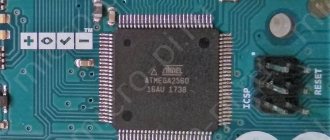
- Arduino Mega Clock frequency ATmega1280 16 MHz with automatic reboot capability.
- Arduino Mini Corresponds to Arduino NG or older versions with ATmega168 (eg: ATmega168 clock speed 16 MHz without auto-reboot capability).
- Arduino BT Clock frequency ATmega168 16 MHz. The Bootloader is loaded together with codes for initializing the Bluetooth module.
- LilyPad Arduino with ATmega328 Clock frequency ATmega328 8 MHz (3.3 V) with automatic reboot capability. Compatible with Arduino Pro or Pro Mini (3.3V, 8MHz) with ATmega328.
- LilyPad Arduino with ATmega168 ATmega168 clock speed 8 MHz.
Compilation and loading corresponds to Arduino Pro or Pro Mini (8 MHz) with ATmega168.The loaded Bootloader has a long timeout (when rebooting, the pin 13 LED blinks three times), because original versions of LilyPad do not support automatic reboot. Also external clocks are not supported and therefore Bootloader configures the ATmega168 to load the internal 8 MHz clock.
If you have later versions of LilyPad (with 6-pin software input), you will need to select Arduino Pro or Pro Mini (8 MHz) with ATmega168 before loading the Bootloader.
- Arduino Pro or Pro Mini (3.3 V, 8 MHz) with ATmega328 ATmega328 clock speed 8 MHz (3.3 V) with automatic reboot capability. Compatible with LilyPad Arduino with ATmega328.
- Arduino Pro or Pro Mini (3.3 V, 8 MHz) with ATmega168 ATmega168 clock speed 8 MHz (3.3 V) with automatic reboot capability.
- Arduino NG or previous versions with ATmega168 ATmega168 clock speed 16 MHz without automatic reboot capability. Compilation and loading corresponds to Arduino Diecimila or Duemilanove with ATmega168, but Bootloader has a long timeout (pin 13 LED flashes three times when rebooting).
- Arduino NG or previous versions with ATmega8 ATmega8 clock speed 16 MHz without automatic reboot capability.