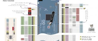
Connection diagram
We connect resistors directly to the RGB pins and Arduino pins. We are using a common anode RGB LED, so the common pin must be connected to 5V. If you are using a common cathode RGB LED, you should connect the common pin (which is longer) to GND (ground) instead.
We'll use digital outputs 3, 4 and 5, but you can use other pins if you want.
Things you'll need
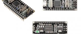
- arduino board
- bluetooth serial module (btm222 module with built-in regulator was used in this article)
- The only problematic part here is the bluetooth module. There are different modules all over the internet, so make sure you check the output in the datasheet you have as it may vary. Also note that there are two general classes of bluetooth modules: Class 1 has a range of about 100 meters. Class 2 has a range of about 10 meters. If you are wondering that they are fully compatible and you can only get 100m if both devices support that range
- The bluetooth serial module used here has the following pins from left to right (ground, RX, TX, not connected, VCC). Obviously, ground and VCC go respectively to the ground and + 5V pin on the arduino. Since we will be receiving data through the module and then in turn sending it to the arduino board, we only need to use the TX pin on the module. Run a wire from this pin to the RX output on the arduino board. Led is controlled using PIN 2 on the Arduino.
- Light-emitting diode
- resistor (100 ohm)
- wires
- bread board
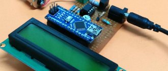
Testing connections
To check if the connection is correct, download the sketch below. The sketch will cycle through the colors: red, green, blue, yellow, purple and light blue.
int redPin = 5; int greenPin = 4; int bluePin = 3; // uncomment this line if you are using a common anode LED #define COMMON_ANODE void setup() { pinMode(redPin, OUTPUT); pinMode(greenPin, OUTPUT); pinMode(bluePin, OUTPUT); } void loop() { setColor(255, 0, 0); // red delay(1000); setColor(0, 255, 0); // green delay(1000); setColor(0, 0, 255); // blue delay(1000); setColor(255, 255, 0); // yellow delay(1000); setColor(80, 0, 80); // purple delay(1000); setColor(0, 255, 255); // aqua delay(1000); } void setColor(int red, int green, int blue) { #ifdef COMMON_ANODE red = 255 — red; green = 255 - green; blue = 255 - blue; #endif analogWrite(redPin, red); analogWrite(greenPin, green); analogWrite(bluePin, blue); }
You should see the LED flashing different colors. In this case, we wired the LED so that the red leg is on pin 5, the green leg is on pin 4, and the blue leg is on pin 3. If the colors don't look right, you can change the numbers to determine which leg is which.
Principles of the project
First, we need to download and install the Bluetooth Terminal App on our smartphone (you can use another similar application) and connect the smartphone to the HC05 Bluetooth module. Then configure the Bluetooth Terminal application as in this article.
Once we have done all this, we will be able to transfer data from our smartphone (from the Bluetooth Terminal app) to the HC05 Bluetooth module, which will then be able to transfer this data via the serial port to the Arduino Mega board. 16×2 LCD display is used to display the status (on/off) of the electronic devices controlled by us. The L293D chip is used to control two relays to which light bulbs are connected. The 12v adapter is used to power the Arduino board and the entire circuit. The block diagram of the device operation is shown in the following figure.
Whenever we transmit data from a smartphone, the Arduino board will check the incoming character and set the voltage to a high or low level on the corresponding pins. Then, using these contacts, relays are controlled through the L293D driver, which turn the light bulbs on and off.
In general, our device will perform the following operations:
- if we transmit the character 'a' through the Bluetooth Terminal app, then light bulb no. 1 will turn on and light bulb no. 2 will turn off;
- if we transmit the character 'b' through the Bluetooth Terminal app, then light bulb no. 1 will turn off and light bulb no. 2 will turn on;
- if we transmit the character 'c' through the Bluetooth Terminal application, then both the light bulbs will turn on;
- if we transmit the character 'd' through the Bluetooth Terminal application, then both the light bulbs will turn off.
You can watch all these processes in more detail in the video at the end of the article.
Control via Serial on Arduino
Now let's implement serial communication to control the color of the LED. We are going to use the code below. Upload this sketch to your board:
// contacts for LEDs: const int redPin = 5; const int greenPin = 4; const int bluePin = 3; void setup() { // initialize serial communication: Serial.begin(9600); // make pins outputs: pinMode(redPin, OUTPUT); pinMode(greenPin, OUTPUT); pinMode(bluePin, OUTPUT); } void loop() { // if there is serial communication, read: while (Serial.available() > 0) { // look for a real integer: int red = Serial.parseInt(); // do it again: int green = Serial.parseInt(); // do it again: int blue = Serial.parseInt(); // look for a new line, end of expression: if (Serial.read() == '\n') { // limit the values to 0-255 and invert: // if the LED is with a common cathode, then use “constrain(color, 0 , 255);" red = 255 — constrain(red, 0, 255); green = 255 — constrain(green, 0, 255); blue = 255 — constrain(blue, 0, 255); // fade out red, green and blue: analogWrite(redPin, red); analogWrite(greenPin, green); analogWrite(bluePin, blue); // print three numbers on one line in hexadecimal: Serial.print(red, HEX); Serial.print(green, HEX); Serial.println(blue, HEX); } } }
After downloading and running the code, open Serial Monitor in the Arduino IDE (Tools -> Serial Monitor). Select 9600 baud (the speed we used in the code) and select "Newline" in the line ending selection box (it's the box to the left of the baud rate selection). This is important because linefeeds are not sent by default and we need to detect the end of the line.
Now type 255,0,0 and press enter to see the LED turn red.
RoboCraft
Due to the fact that I am planning to create my own robot controlled via XBee, the brain of which will be a computer, there was a need to master in advance the control of Arduino using a USB interface.
As a result, a program will be created that controls the LED and has 4 modes - lit, not lit, blinking, blinking n times.
The Russian Qt library qserialdevice will be used. You can download it here: qserialdevice
Just type git clone https://gitorious.org/qserialdevice
and it will appear in the current folder. Next, follow the instructions in the Readme_ru.txt file.
It’s worth saying right away that Arduino has a built-in USB-UART FT232R converter that provides a virtual COM port, so managing the board is not difficult. All the difficult work of switching PC->Arduino will be done for you by the converter and the driver for it, which is usually already on your OS.
It’s also probably worth knowing that if you use Linux you can send data like this: echo _SIGNAL_DATA_ >> /dev/ttyUSB0
Let's start creating a Qt application. First you need to create an interface, a shell, and then implement sending data to Arduino at the user's request.
Note for Linux Users
1. You will need to add to the .pro project file: LIBS += -lqserialdevice
If the library is not found during compilation, then go to the qserialdevice library directory through the terminal qserialdevice/src/build/release and copy it to the library folder /usr/lib/: sudo cp libqserialdevice.a /usr/lib
2. Header files also need to be copied. Create a directory with sudo mkdir /usr/include/qserialdevice . Go to /qserialdevice/src/qserialdevice and copy to /usr/include/: sudo cp * /usr/include/qserialdevice
Then go up a level and copy another important file: cd .. && sudo cp qserialdevice_global.h /usr/include/
Now you can fully use the library.
We create a Qt GUI project using the usual method without a form. In the MainWindow constructor we write:
widget = new QWidget(); grid = new QGridLayout(); button_show = new QPushButton("Show"); button_hide = new QPushButton("Hide"); button_blink = new QPushButton("Blink"); button_blink_n = new QPushButton("Blink 0"); editLine = new QLineEdit("0"); connect(editLine, SIGNAL(textChanged(QString)), this, SLOT(setButtonBlinkN(QString))); editLine->setInputMask("9"); grid->addWidget(button_show, 0, 0); grid->addWidget(button_hide, 0, 1); grid->addWidget(button_blink, 0, 2); grid->addWidget(editLine, 0, 3); grid->addWidget(button_blink_n, 0, 4); widget->setLayout(grid); setCentralWidget(widget);
We will consider the GUI ready. The entire code with comments is available at this link:
source
Now it's time to implement work with the USB interface. At first I wanted to make my own wrapper class for work, but the qserialdevice library is already sufficiently abstracted so there is no need for this.
Let's start by creating the initialization function initSerial():
AbstractSerial* serial; ... bool MainWindow::initSerial(QString dev, int baudRate) { serial = new AbstractSerial(); serial->setDeviceName(dev); if(serial->open(AbstractSerial::ReadWrite)) { serial->setBaudRate(baudRate); } else { return false; } return true; }
The function initializes the AbstractSerial object - the device dev and speed baudRate are indicated. If successful, returns true, otherwise false.
Using the function in the MainWindow constructor looks like this:
if(initSerial(tr(“/dev/ttyUSB0”), 9600) == false) { qDebug() Next, we create a function to send data. void MainWindow::send(QByteArray &ba) { serial->write(ba); } A very simple function. All it does is send a QByteArray byte array to the port. The QByteArray data array is a very convenient class. It has many convenient methods for working with byte arrays - clear, resize, etc. Now all that remains is to create button click handlers (slots) and connect them to the buttons. /* Not Light */ void MainWindow::ShowLigth() { ba[0] = 'S'; send(ba); } void MainWindow::HideLigth() { ba[0] = 'H'; send(ba); } void MainWindow::Blink() { ba[0] = 'B'; send(ba); } void MainWindow::BlinkN() { ba[0] = 'N'; send(ba); ba[0] = (char)editLine->text().toLocal8Bit().at(0); send(ba); } ShowLigth - turn on the LED, HideLigth - turn it off, Blink - give a command to blink (yes, I have this function implemented in the arduino itself, but it doesn’t matter, everyone chooses the implementation method), BlinkN - give a command to blink and send the required number of blinks . Connecting buttons with handlers in the MainWindow constructor: connect(button_show, SIGNAL(clicked()), this, SLOT(ShowLigth())); connect(button_hide, SIGNAL(clicked()), this, SLOT(HideLigth())); connect(button_blink, SIGNAL(clicked()), this, SLOT(Blink())); connect(button_blink_n, SIGNAL(clicked()), this, SLOT(BlinkN())); That's it, now the desired functionality of the program is implemented! https://www.youtube.com/watch?v=Drf-hAPUkMY Now, as a bonus, I will create a handler for receiving data and outputting it to the terminal. Create a slot for receiving data: void MainWindow::ReadData() { qDebug() readAll(); } Again, very simple. I used the qDebug() function, it has a little specific output, but it is suitable for demonstration. We associate the slot with the event in the initSerial function: connect(serial, SIGNAL(readyRead()), this, SLOT(ReadData()));
That's all! Now you can create full-fledged Qt applications that can communicate with your Arduino board or other device. It is worth expressing respect to the creator of qserialdevice because... It's actually a very convenient and simple library. You can download the source code of the Qt application here: https://narod.ru/disk/15839336001/ArduinoLigth4.tar.gz.html Download qserialdevice: https://gitorious.org/qserialdevice Download the firmware that I used for arduino: https:/ /narod.ru/disk/15839579001/Blink_serial.pde.html Video demonstration on YouTube: https://www.youtube.com/watch?v=Drf-hAPUkMY My blog: https://hacking-root.blogspot.com /
Writing a sketch
The data that the Bluetooth module receives comes via UART (aka Serial connection) at a speed of 9600 bps. There is no need to configure the Bluetooth module: it is immediately ready for use. Therefore, the sketch should be able to do the following:
Features of sketch filling
To communicate Bluetooth-Bee with the controller, the same pins (0 and 1) are used as for the firmware. Therefore, when programming the controller, the “SERIAL SELECT” switch on the “Wireless Shield” must be set to the “USB” position, and after flashing it must be returned to the “MICRO” position.
Bluetooth Controller 8 Lamp
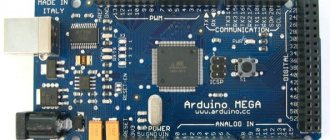
The Arduino platform was created in 2003. It achieved universal attention thanks to its low price, as well as a multi-million dollar community aimed at in-depth study of programming. Microprocessors and microcontrollers come with boards. Arduino is considered the most popular. Italian models have many functions to expand and explore built-in Pro systems.
Bluetooth Controller 8 Lamp is designed to regulate the functions of Arduino with an 8-channel controller. Works using Bluetooth modules HC-05, HC-06 and HC-07. 8 button interface corresponds to each light bulb.
The method is active only within visibility. Compared to other wireless methods, this is the cheapest. Board components cost less than $1. Even used options are suitable for the job. Static devices, using an infrared controller in ceiling LED strips, easily solve problems that arise during the process.
Virtuino
An Android program designed to monitor the sensor. Controls electrical devices via Bluetooth, Wi-Fi or the Internet.
With the help of Virtuino you can create:
The application is able to combine several projects into one. Controls excellent platforms simultaneously via Bluetooth and Wi-fi. Free to use. Belongs to the System Maintenance subcategory. It is possible to design interior design with different visualizations.
You can learn Virtuino using tutorials and video lessons with library support. For now the application works in English mode.
BT Voice Control for Arduino
The main purpose of this software is to transmit ultrasonic signals through transducers. They are connected to the Arduino android platform thanks to the Bluetooth port. The main module in operation is HC-05. It conveys the spacing between objects. The data is displayed on the smartphone and on the Hub disk of the portal through this application.
BT Voice Control is Arduino voice control. It has the command recognition function: forward, back, left, right. Sensitive sensors forward the distance to the Arduino object. Then, using the Bluetooth module, the HC-05 sends it to the application. The program will save time spent typing commands manually.
Blynk app
A sort of idea developer with an open door to launch on the Arduino platform. The main requirement for use is the presence of the Internet: Wi-Fi or mobile traffic. Only in this case will Blynk be ready for execution. You can start using it a few minutes after completing the settings. The program supports the AO of the user's choice.
The main functions of the Blynk application are to manage devices by removing and adding HTTP protocols, as well as GET and POST requests. Parameter values can be updated and retrieved. Requests are updated in the application itself.
Variability is an important point of the program. Having a connection with running platforms, you can connect to the server in any convenient way. This instinctive portal is easy to use on a project. The library is constantly updated for all Arduino Blynk applications.
Customers who want to turn on the coffee machine from their smartphone will be interested in this application. This is perhaps the only service with such capabilities. And despite the fact that it is practically unlimited, Openhab is difficult. Compared to other services, it has fast startup speed.
Installing Python on your computer
This section of the article will discuss installing a programming language on a computer with 32 or 64-bit Windows. Installing Python on MAC and Linux computers will be different. To install Python, follow these steps:
1. Install the 32-bit version of Python 2.7.9 IDLE on your computer. Do not download the 64-bit version of Python or its newer version as they may not be compatible with the Arduino libraries we use. Even if your computer runs on a 64-bit operating system, you can still use the 32-bit version of Python on it.
Note : This article was originally written in 2022, so the Arduino IDE may now be compatible with newer versions of Python (this will be updated later).
2. Run the downloaded installation file and install this version of the Python language on your computer. Do not change the Python installation directory, leave it as default - C:\Python27.
3. It is possible that during the installation of Python the antivirus will “swear” at it - do not pay attention to this.
After installing Python, you can check whether it is actually installed on your computer by entering “Python IDLE” in the Windows search bar.
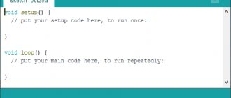
After launching it, you should see “Python shell” on your computer screen as shown in the following figure.
You can directly write a program in this shell, or you can create a new file and write and test the program in it. Now let's make sure Python is working. To do this, type “print (1+1)” and press enter. You should then see the printed result of the calculation in the shell - 2.
Receiving example
The picture below shows an example of retrieving data from an Android phone. The Arduino development board uses a DS18B20 temperature sensor to obtain the temperature value. The Android app updates the temperature every 15 seconds. To better display the effect, I implemented a voice broadcast from a mobile phone. The Arduino code and application program will be described in detail in the following steps 4, 5 and 6.
Rice. 3. Android phone shows the ambient temperature.
Next, I will introduce the connection method step by step, write an Arduino sketch that can send and receive commands, and write an application. This tutorial requires you to have a basic understanding of Arduino, be familiar with its IDE, and best complete a few small projects. In this case, the contents of this tutorial will be very easy to understand and it will be very easy for you to implement serial communication with Arduino.
USB Serial Library
Setting up a serial connection in Android is quite labor intensive as it requires you to manually configure a lot of things, so I found a few libraries that do it all automatically. I tested several of them and finally settled on the UsbSerial library from Github user felHR85. Among similar libraries that I found, it is the only one that is still updated. It's quite easy to set up and use. To add the library to your project, download the latest JAR file from Github. Place it in the libs subdirectory of your project directory. Then, in the file explorer in Android Studio, right-click on the JAR file and select “Add as Library”. That's all!
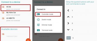
Arduino Bluetooth Controller
This program works in 3 main positions:
Controller. The application is displayed in the form of a play identifier and is controlled by switch buttons. It operates with one key, the main function of which is remote control.
Dimmer. From a distance, adjusts brightness and speed settings.
Terminal. Implementation of sending directive for decryption.
Installing the Arduino Bluetooth Controller app connects multiple devices over the air. Messages are transmitted to sensors, controllers and back. By controlling a smartphone using Bluetooth modules, it is also possible to organize a wireless connection for an entire project. Programming of this type is accessible to everyone and does not require much effort.
Arduino 2 Reference
Arduino 2 Reference
This is one of the important applications for learning Arduino. New users will only need a couple of weeks to master the material with this application. The application is available offline, which allows you to study the material anywhere without an Internet connection. Categories included are: operators, data, functions and some Arduino libraries.
Rating on Google Play: 4.7 out of 5
Number of downloads: more than 50,000