Sections of the site
DirectAdvert NEWS
friends of site
Action Teaser NEWS
Statistics
Power supply for car amplifier. Fuse selection. Selecting a capacitor.
Car amplifier power supply_fuse_capacitor
In the last article, we looked at two ways to calculate the cross-section of cable cores to power a car amplifier. Let's start this article with the fact that it is better to pull this cable (both plus and minus power) directly from the battery terminals. Many car enthusiasts only take the “plus” from the battery, and take the minus from the nearest bolt of the car body, because the body is the “minus” of the on-board network. This is not entirely correct for connecting audio equipment, especially if you want to achieve a good result and do everything, as they say, according to “Feng Shui”. There are plenty of explanations for this on the Internet, so we won’t delve deeply into the explanations; let’s just say that it all comes down to transition resistances and the voltage drop on the supply line.
The second point is that the fuse protecting the power cable is placed on the “plus” as close as possible to the battery terminal. Please note that the fuses installed in the amplifier do not protect the power cable, so the absence of a main fuse may lead to a fire in the power cable if there is a short circuit. The cross-section of the negative conductor must be no less than the cross-section of the positive conductor of the supply cable. Splices of the supply cable are not allowed.
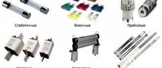
To protect the power cables of car amplifiers, fuses of the AGU, mini-ANL and ANL types are used.
The picture below shows an AGU type fuse and a bulb for this type of fuse:
Mini-ANL type fuses and their holders are as follows:
Depending on the rating, mini-ANL fuses can protect power cables with core cross-sections up to 35 mm2.
The following image shows ANL type fuses:
These fuses are available in ratings from 15 to 300 Amps. Depending on the manufacturer, all of the above fuses may have holders slightly different from those shown in the pictures.
The answer to this question directly depends on the cross-section of the supply cable cores. It is clear that if a short circuit occurs in the power cable, the fuse should burn out, and not the cable itself. Therefore, based on the data from the first table of the previous article on cable parameters, the following table was compiled, from which you can easily select the fuse rating depending on the cross-section of the cable cores. But keep in mind that this rating should not be less than that installed in the amplifier itself, and if you have a similar situation, then you most likely made a mistake when choosing the cable gauge.
A typical power wiring diagram is shown in the following figure:
Naturally not for twisting. There must be a reliable bolted connection. Either copper lugs are crimped onto the ends of the cable and seated under the existing bolts on the terminals, or the standard terminals are replaced with those shown in the following figure:
For power distribution, for example, to connect two or more amplifiers, power distributors are used. See images below:
Phonocar Connections and Stinger SPD511 power distributors are conventional power strips that do not have built-in fuses.
You can also use fuse distribution blocks for power distribution; they look like this:
Option for connecting power to two car amplifiers:
For information on choosing a cable cross-section (caliber), read the previous article:
When moving from the engine compartment of the power cable to the car interior, it would not be superfluous to install gland entries; this will eliminate the possibility of the cable insulation rubbing against the cutting edges of the drilled hole and causing a short circuit of the positive wire to the car body. See photo below:
As you know, a capacitor is an element capable of storing electrical energy and releasing this energy when it is needed. In our case, it supplies power to a powerful amplifier, and when the amplifier reproduces powerful bass, peak values of the current consumed by the amplifier are created, which leads to a voltage drop in the car’s on-board network (at this moment, the dashboard backlights may dim). This, in turn, can lead to sound distortion, clipping, not clearly defined (blurred) bass, and other consequences that negatively affect the quality of playback of the music signal. The sound is, of course, disgusting. All these problems are solved by installing an electrolytic capacitor, which is connected to the same terminals of the amplifier where the power comes, observing the polarity.
What capacitor value should I choose?
Some music lovers use the principle “You can’t spoil porridge with butter.” Well, in general, it is customary to install a capacitor with a capacity of 1 F (Farad) to an amplifier with a power of 1 kW. And if you use a less powerful amplifier, for example 500 watts, then setting the electrolyte to 1 Farad will end up with a double margin, and this is normal.
Principle of operation
If you personally have not had to repair any equipment, or simply disassemble it, then only a photo of a fuse will help you understand what this important part of any serious device is.
As you can already understand from the name of the part, its main purpose is to prevent damage that can be caused to microcircuits and the circuit as a whole by overvoltage in the electrical network.
This is because it is much easier to change one small part, which goes at the beginning of the entire circuit on the microcircuit, than to repair or even replace more important parts.
This fuse gets its name from the material that is used inside it, namely its low melting point.
Such a reaction can be caused by several situations, including a banal short circuit, short-term surges in the electrical network, or a full-fledged overvoltage, which can be caused by a malfunction of a transformer substation, for example.
Current breaking capacity
In the event of a short circuit, the main circuit breaker or fuse must break the circuit through which a very high current flows. If the protection device is not designed for this, an electric arc may occur, the contacts of the machine will weld together and the circuit will not open. The ability of a circuit breaker or fuse to trip during a short circuit is characterized by its current interrupting capacity (AIC).
AIC is the maximum current a device can cut at a given voltage. The expected short circuit current must not exceed the current breaking capacity. The short circuit current in 12 and 24 volt DC systems depends on the battery's cold cranking amps (CCA).
| Battery cold start current, A | Battery capacity, Ah | Current breaking capacity, A |
| 650 and less | 140 | 1500 |
| 651-1100 | 141-255 | 3000 |
| 1101 — 2200 | 256-500 | 5000 |
| Over 2200 | More than 500 | Equal to the short circuit current specified by the battery manufacturer or 100 x battery capacity |
The data presented in the table applies only to gel, AGM and liquid acid batteries. The short circuit current of some types of AGM and especially lithium batteries is significantly higher.
If the breaking capacity of the circuit breaker does not match the capacity of the battery, a fuse with an appropriate AIC is installed between the circuit breaker and the battery. For example, Class T (AIC - 20,000 A)
If the system voltage is less than the rated fuse (for Class T 160 V), the breaking capacity increases approximately in proportion to the voltage ratio. It can be more accurately calculated using the formula - (Nominal voltage/system voltage) x AIC x 0.5. For a Class T fuse used in a 12 volt electrical system, the current breaking capacity is (160/12) x 20,000 x 0.5 = 133,000 A.
For fuses rated less than 30 amps in a 12-volt electrical system and less than 15 amps in a 24-volt electrical system, the current breaking capacity is not required.
Device
Despite the fact that the markings of the fuses may differ, and, consequently, the overvoltage limits in which they should be used, the general design of the part remains the same.
As we have already discussed above, its most important part is the conductor, which melts under certain conditions. It is mounted inside the housing, which is designed to more conveniently fix the part inside the device and to concentrate the molten conductor in case of overvoltage.
zom81e › Blog › About installing relays in theory and examples. Part 1
Quite often I have to help with connecting fog lights and other additional equipment.
The main problem that novice cadet teachers and others face is connecting the relay. To help in this matter, it was decided to make instructions for this process, or rather a short series of posts devoted to this topic. Task.
We have at our disposal an OPEL KADETT car, in which fog lights have never been installed before. The existing configuration did not include any wiring for this, and I really want to install a set of universal fog lights. Therefore, we will carry out the installation, as they say, from scratch. They say that they need to be connected via a relay. What does it look like, what does it do and most importantly, how do you connect it? I won't explain all of this. There are plenty of articles on the Internet with this information. Here we will only consider connection options.
Solution.
We go to the market/to a car store/via a browser to an online store, etc. and buy the set of fog lights you like. If you didn't save money, the kit will include all the necessary installation elements. If you still want to save money or got the headlights from your brother/godfather/neighbor, then you need to buy something extra. Further, I will not stipulate that you need wires and corresponding terminals, but will focus only on the main elements. To turn on and off additional headlights in a timely manner, we will need a button. There is no way without this, because we all know the rules of the road. To do this, purchase the one you like (preferably with backlighting and position indication) and embed it into the panels in a place convenient for you, or buy a standard button. Of course, I will not describe the first option, because I cannot predict the future, and especially yours. But if you settled on a standard button, then the diagrams indicate the numbers of contacts that correspond to it. All contact numbers on buttons/relays/switches, etc., which are in the diagrams below, can be found on their body or plug/connector in the form of small numbers in the appropriate places. So, relay. There are mainly 3 types of automotive relays available on the shelves.
Option 1.
4-pin with built-in fuse. I believe that this is the most successful option for installing such equipment. The advantages of this design are that the number of handmade twists/solders along the power wire path is reduced, which has a positive effect on the reliability of the wiring and the voltage drop along the way to the consumer. There is also a drawback - if the installation location is poor, where the relay can get into an aggressive environment such as moisture, the contacts may become contaminated. The latter impairs conductivity, which can lead to failure of the relay itself and worsen the performance of the consumer. In the worst case, the wires may be destroyed. But this is unlikely. Such a relay looks like this:
The connection diagram in this case will be like this:
Option 2.
4-pin regular relay. A very rare guest on the shelves today (at least I rarely saw them), but often found in the bins of experienced drivers of the Soviet era. It looks like this:
To connect using this relay, it is additionally necessary to provide (read purchase) the installation of a fuse to prevent negative consequences in the wiring. I advise you to pay attention to special holders. They look like a plastic fuse housing. There are also “rubber” versions with increased moisture resistance. We buy what we like. In general they look something like this:
I recommend connecting with this type of relay according to the following diagram:
Option 3.
5-pin regular relay. Perhaps the most common type. Looks like that:
It is with this that connection difficulties most often arise. What else is typical for this type of relay is that you can easily buy a block/connector for them. Then this set will be something like this:
Installation using this block certainly makes the process much easier, but unfortunately it also has a drawback. These are just another twisting/soldering of wires. So everyone is free to do their own thing: simply crimp the wires with terminals, crimp and install them in the block (the most correct, but expensive and time-consuming option), “twist” the standard wires of the block with your own wiring. As in the previous case, you will also have to install an additional fuse. And of course, the connection diagram with this type of relay is presented below:
The following symbols are used in the diagrams presented above:
My circuits will work as follows. When you turn on the headlights (+ illumination of the instrument panel and some switches), the button illumination will light up and it will be possible to turn on the fog lights. The same will happen in low/high beam. When the lights are turned off, the PTF will also turn off. Let me remind you that according to traffic regulations, you cannot use PTF with high beams. Therefore, these circuits are made with the simplest connection method in mind and for a conscious driver who does not forget about his switches. If you follow the rules and regulations, then all circuits will require the addition of another relay, which will turn off the PTF in high beam mode. If anyone is interested, I can add more.
Another issue that must be resolved when preparing a new branch of electrical consumers is the fuse rating. In the diagrams above, it is 20 A. This was done on the basis that most relays sold are designed for maximum currents of about 30 A. That is, if during the calculation it turns out that consumers need a current of more than 20 A, I advise you to complicate the circuits and use several relays for each individual or group of consumers. Looking ahead a little, I will say that for installing PTFs with lamps with a power of 90...100 W, these ratings are quite sufficient. Now a little more specific. There is a formula that is included in the basic course of the school curriculum. But we were at school for a long time. Let us remind you: electrical power is equal to the product of voltage and current (P = U*I). Let's look at the most common options: For two PTF lamps with a power of 55 W each, a current rating of (55 W * 2 headlights) / 13 V = 8.5 A is required. That is, the fuse must have a minimum rating of 10 A. But taking into account such a thing as starting current, it is recommended increase this number by 1.2...1.5 times. Those. the optimal fuse would be a 15 A rating. For two PTF lamps with a power of 100 W each, a current rating of (100 W * 2 headlights) / 13 V = 15.4 A is required. In this case, it is necessary to install a fuse with a rating of 20 or 25 A.
Source
Advantages and disadvantages
We have already figured out how a fuse works, so it is worth considering their advantages and disadvantages.
Their main advantage can be considered their low price. Knowing this, it is especially surprising how some unscrupulous manufacturers save on this detail, understanding what such a decision can lead to.
UPS for home: types, design and operating featuresWhat is an intermediate relay: design, principle of operation, device and application ideas (115 photos)
Homemade 12 volt power supply: selection of components and simple circuits for creating with your own hands. 130 photos of homemade universal blocks
Despite this, there are certain disadvantages. Regardless of the type of fuse, its response time will always be higher than that of its automatic counterpart.
If you use just such a fuse to protect a device in a high-voltage network, you may encounter a situation where it simply did not have time to melt before the surge reached the important components of the device.
In addition, such a part is cheap for a reason, because in fact it is disposable. As soon as the fuse has blown, the device needs to be serviced by a technician who will replace the unusable part.
At the same time, automatic fuses can work for a long time, because they simply open the circuit in certain situations, without losing their functionality.
Important points
In the end, we summarize all the main aspects that need to be observed in order to connect the amplifier correctly and safely:
- Select a power cable of sufficient cross-section, preferably with a margin.
- Select the correct fuse.
- All contacts must be stripped and tightly tightened or crimped (the larger the contact area, the better).
- Knock out quality copper wiring.
- Protect cables from damage with additional insulation.
- Lay acoustic and signal wiring as far as possible from the power supply.
- If you have several amplifiers and the minus is taken from the body, then make contact for all at one point.
- Make all connections on a de-energized system (positive terminal with battery removed).
In order to make the installation of a car amplifier safe, you need to protect the power wiring from the battery to the amplifier with a fuse. Here is a typical amplifier connection diagram:
In most cars, the battery is located under the hood near the engine, and the amplifier is most often located in the trunk or inside the car. In order to supply power to the amplifier, a large cross-section power wire is used, which runs through the entire interior of the car. If the amplifier is located in the trunk and the battery is under the hood, then in an average car 5-6 m are required. power wire to connect the amplifier. In this case, the wire passes through at least one metal wall (the wall of the engine compartment), passes under the carpet in the cabin, behind the trunk trim. The wire runs near the metal body of the car, a short circuit to which will lead to a fire! Even if you routed the wire very competently, using rubber bushings or other safe transitions when passing the wire through the wall of the engine compartment and the wire along its entire length is additionally secured and protected by a corrugated tube, there is a possibility (albeit small, but still!) of a short circuit, for example in the event of an accident. You don’t want your car to look like this because of penny savings:
Photos of fuses
Reinforcing shears (bolt cutters): types, characteristics, main differencesHow a voltage control relay works: the principle of operation of the protection and the nuances of connecting a control relay for a house or apartment
- What is a pulse relay: principle of operation, types, description of devices and connection diagrams. 155 photos of pulse-type relays and video installation instructions
Did you like the article? Share
0
Relay VAZ 2106
The following shows the location and designation of each factory relay:
- Voltage regulator, which is responsible for proper charging of the battery. Located on the left mudguard.
Battery charge voltage regulator relay - Turning on the radiator cooling fan. It is also located on the left mudguard, behind the expansion tank. Radiator fan relay
- A light on the dashboard that indicates battery charging. The relay is already located on the right mudguard.
Battery charging light relay - Low and high beam headlights. They are also located on the right mudguard. They are identical and interchangeable.
Relay for low and high beam headlights - Turn and hazard warning relay. It is located behind the instrument panel, approximately behind the tachometer.
- The wiper relay is located on the left side, under the instrument panel.
The video below clearly shows where which relay is located.
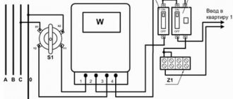
Table of external connections and connectors of the VAZ-2110 mounting block.
| Block | № | Color | Electrical circuits |
| Ш1 | 1 | ZhCh | fog lamp (left) |
| 2 | GP | trunk lock motor, heated seats | |
| 3 | R | door lock relay | |
| 4 | ABOUT | power window relay | |
| 5 | ZhP | fog light relay | |
| 6 | AND | fog lamp (right) | |
| 7 | MS | power window relay | |
| 8 | — | reserve | |
| Ш2 | 1 | — | reserve |
| 2 | — | reserve | |
| 3 | — | reserve | |
| 4 | H | weight " - " | |
| 5 | ZhP | size (left rear) | |
| 6 | Warhead | outdoor light switch | |
| 7 | — | reserve | |
| 8 | ZhCh | license plate lamps, off instrument lighting | |
| 9 | KP | size (right rear) | |
| 10 | TO | size (right) | |
| 11 | ZhG | email windshield wiper motor, windshield wiper and washer switch. | |
| 12 | Z | outdoor light switch | |
| 13 | ABOUT | fog light switch | |
| 14 | Emergency | hazard switch | |
| 15 | — | reserve | |
| 16 | GP | Ignition switch (terminal 15), steering column switch | |
| 17 | R | windshield wiper and washer switch | |
| 18 | JV | steering column headlight switch | |
| 19 | — | reserve | |
| 20 | — | reserve | |
| 21 | AND | size (left) | |
| Ш3 | 1 | midrange | low beam (left headlight) |
| 2 | — | reserve | |
| 3 | WITH | low beam (right headlight) | |
| 4 | R | generator (cl. 30) | |
| 5 | TO | generator (cl. 30) | |
| 6 | TO | generator (cl. 30) | |
| Ш4 | 1 | PZ | on-board display system |
| 2 | GO | hazard switch | |
| 3 | IF | hazard switch | |
| 4 | H | weight " - " | |
| 5 | PG | portable lamp plug | |
| 6 | Salary | heated rear window switch, heated rear window lamp | |
| 7 | — | reserve | |
| 8 | — | reserve | |
| 9 | — | reserve | |
| 10 | ZhZ | steering column washer and windshield wiper switch | |
| 11 | B | email windshield wiper motor | |
| 12 | BW | steering column washer and windshield wiper switch | |
| 13 | GB | steering column switch, ignition switch lamp | |
| 14 | BP | brake lights, clock, interior lamp | |
| 15 | P | brake lights | |
| 16 | RP | off brake lights | |
| 17 | ABOUT | generator (cl. 30) | |
| Ш5 | 1 | AF | high beam (left lamp) |
| 2 | JV | rear window heating element | |
| 3 | G | heater controller, glove compartment lamp | |
| 4 | Z | high beam (right lamp) | |
| 5 | ZhG | Windshield wiper motor, SAUO recirculation valve | |
| 6 | PB | email cooling fan, beep |
Circuits protected by additional fuses (all fuses are 15 A) on the VAZ-2110:
Additional fuses: 1 – ignition module, controller; 2 – canister purge valve, vehicle speed sensor, oxygen (heating) sensor, air flow sensor; 3 – fuel pump relay, fuel pump, injectors.
Additional relays: 4 – electric fan relay; 5 – electric fuel pump relay; 6 – main relay (ignition relay).
There is a fog lamp fuse installed in the niche of the instrument panel behind the mounting block:
"Euroblock" VAZ 2106 (new model), diagram
Below is a picture of what the Eurobloc looks like in real life.
Photo of Euro block VAZ 2106
Below is the pinout of the new type of power supply or, as people say, “Euroblock”. The diagram also shows which fuse is responsible for what.
VAZ 2106 fuse block diagram with decoding