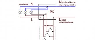
Connection diagram for a lamp when combining a socket and a switch in one unit
A socket and a switch combined in one housing are far from uncommon. Today factories produce them in large quantities. Their main advantages are saving wires and space, lower labor and time costs and high operational safety. To connect the device to a light bulb, you must perform the following steps:
- Prepare a place on the wall surface for a socket box. Modern houses made of reinforced concrete elements already have mounting holes with wiring. If they are not there, you need to use a hammer drill. In wooden houses, overhead structures with external wiring are often used.
- A two-core wire is laid from the main electrical panel to the distribution box. Phase and zero will follow it.
- You also need to connect the para-core conductor from the light bulb and three wires from the block with the switch and socket to the distribution housing.
- The current source in the panel is connected with wires: the phase is sent to the socket and switch.
- The neutral conductors of the light bulb and socket must be connected to a similar wire of the general electrical network.
- The remaining two wires (coming from the chandelier socket and the switch) are combined and isolated.
- If there is a ground conductor in the housing of the socket switch, it is necessary to connect it to the ground conductor.
This connection diagram will allow you to use devices combined into one module independently of each other. However, there is another technique - when current is supplied to the outlet in the switched position and vice versa. With this option, the algorithm of actions is as follows:
- The installation site is being prepared (according to the diagram above).
- Three two-wire conductors are supplied to the distribution box - in pairs (phase + zero) from the socket, switch and panel.
- The phase conductor of the common network must be connected to a similar wire of the switch.
- The zero branch is twisted with the wire from the outlet
- The two remaining free conductors in the device are connected to each other.
Important! The given connection diagram for an socket switched by means of a switch is suitable for rare use. For example, it can be used to turn on and off a light bulb in a basement powered by an extension cord with a plug.
Types of junction boxes
At the moment, the market offers a wide variety of junction boxes of a wide variety of designs and shapes.
Our article discusses only the box for connecting hidden wiring. Therefore, we will dwell in detail on products of this type.
So:
- First of all, all distribution boxes can be divided according to their shape. For hidden wiring, round ones are most often used. Their diameter and depth can vary greatly. So the diameter usually ranges from 60 to 100 mm, but the depth is usually from 30 to 50 mm. But if you have the right desire, you can find junction boxes for hidden wiring in other sizes.
- Square boxes are also widely used. Usually their sizes are comparable to those of round products. That is, starting from 60×60 mm and ending with products larger than 110 mm. The depth of square boxes usually does not exceed 30 - 50 mm.
- Rectangular junction boxes are also widely used. Here the range of sizes is even greater, but the total area is comparable to boxes of other shapes. Rectangular and square boxes for hidden wiring are used a little less frequently, although here it all depends on your wishes and technical conditions.
- In addition, junction boxes for hidden wiring differ in the material they are made of. According to clause 2.1.27 of the Electrical Installation Rules, they must be made of fireproof and non-combustible materials. When laying wires over combustible materials, metal junction boxes should be used. If the wire is laid using fireproof materials, then using fire-resistant plastic boxes is sufficient.
- If previously all distribution boxes were made hollow, now models with terminal blocks inside have appeared on the market. This allows for better connection of wires, and also helps to organize them inside the box. And although the price of such products is somewhat higher, their convenience is undeniable.
- Well, the last and very conditional division of distribution boxes is the presence of fastenings. It allows you to fix the products in the wall more efficiently and reliably, but if they are mounted on cement mortar, this advantage is very doubtful.
How to connect a single-key switch from an outlet
Often, in solving practical problems when connecting additional lamps or just light bulbs, the need arises to connect a switch from the outlet. You can do this in two ways:
- By connecting the phase from the socket and the neutral to the ground from the distribution box, when the lamp is close to the latter.
- Connecting phase, neutral and ground from the socket when the light bulb is far from the source and pulling wires across the entire apartment is impractical.
Interesting! Ultimately, it is up to the owner to decide which option to choose. However, it should be taken into account that if the outlet is constantly loaded with powerful devices, then its contacts can quickly weaken. Over time, this will lead to deterioration of the lighting device's power supply. The mechanism of sequential actions for connection for both versions is no different (except for the connected power) from when the socket outlet is already connected and in operation, and is given below.
If you need to install a switch from an existing outlet
If the outlet is already installed and connected, you can also connect a light switch to it. There are also two options here, the choice between which depends on the location of the chandelier. The difference between them lies in the distance of the lamp from the socket - if close, then the neutral core is in contact with it, if far away, then from the shield. Let's consider both methods.
Phase and neutral supply from the socket
The easiest option is when both phase and zero are connected to the switch from the outlet. It is applicable if the light bulb/lamp is located very close. To connect them, you need to do the following:
- First of all, you need to install the chandelier itself, and then, according to all the rules, connect the switch to it through wiring.
- The connection procedure must begin with a circuit break - de-energization. This can be done by turning off either the group switch (for the room, if there is one) or the common switch (for the entire apartment/house).
- Next, open the socket cover and check the current at its contacts using a special measuring device (screwdriver with a light bulb).
- A conductor leading to the switch input is connected to the contact with the phase. The output is connected to the core of the lamp itself.
- A conductor suitable for the terminal from the lighting device is attached to the zero contact.
- If there is a grounding contact, then it must also be connected to the corresponding conductor of the chandelier.
- After all the wires have been correctly twisted, the contacts are closed, the wires are laid in their intended place, and the entire assembled system is tested after applying voltage.
Important! When all electrical appliances in a residential area are connected in accordance with PUE standards, in particular, paragraph 1.1.29, then the zero will correspond to a blue conductor, and the ground will have a yellow-green hue. Therefore, determining the phase will not be difficult. Otherwise, a temporary voltage supply will be required for identification using the device.
Connecting only phase
Now let's consider the option of how to connect a switch to an outlet if the chandelier is located in close proximity to the switchboard. To do this you need to do the following:
Where and how to install distribution boxes
Usually the boxes are located under the ceiling at a distance of 100-200 mm from it. The specific value depends on the height of the room. If the wiring is hidden, then the product is placed inside the wall to a certain depth so that the surface of the cover is flush with the wall. For open-type electrical wiring, external boxes are suitable.
In accordance with the rules for the construction of electrical installations (PUE), it is important to provide free access to the junction box cover, which is necessary in case of inspection or troubleshooting. If the product is external and attached directly to the wall, then this condition is met automatically
When placing the device in a wall recess, two requirements must be met. Firstly, you need to know where it is installed, and secondly, you should ensure timely access to the product without compromising its aesthetics. If the latter can be neglected without violating the PUE, then the first requirement is mandatory and important.
You can maintain an aesthetic appearance by gluing beautiful wallpaper, and then carefully trim around the lid of the junction box without removing the part that is glued to it. When choosing alternative finishes, make sure that the color of the surface of the lid and the wall are identical. Try to make sure that if you need to remove the cover, the wall in this place does not collapse. If suspended ceilings are installed, then small hatches should be created to provide access to the boxes.
Is it possible to connect an outlet to the switch?
Full joint operation of the socket and switch, if the first is powered by the latter, is almost impossible. However, there are some variable methods to combine them. Let's look at them in detail.
Socket instead of switch
You can install an socket instead of an existing switch, for example, when you need to carry out a number of temporary repairs or decoration work using electrical equipment or connect a light bulb on a portable device. In this case, you need to perform the following series of actions:
- Turn off the machine - de-energize the network. Before work, you need to make sure that there is no voltage on the contacts using a test probe.
- Disassemble the switch and remove the wiring that goes to it.
- Dismantle the base of the switch, and in its place install a socket and connect its contacts to the freed wires.
- Next, you need to remove the cover of the junction box and disconnect the wires from the former switch from the wires going to the light bulb.
- Connect one of the conductors from the new outlet to the phase, the other to zero and cover them with a layer of insulation; the wires from the lamp are temporarily brought together and insulated.
- Close the distribution module cover and turn on the switch.
- Check the socket, for example, by connecting a plug with an adapter and a light bulb. If it lights up, the circuit is assembled correctly.
Connection from double switch
A two-key switch can also be connected to a power outlet to power electrical appliances, but in this case only one key will work. The algorithm of actions is as follows:
- It is necessary to de-energize the electrical network, be sure to check the contacts with a measuring probe before work.
- Install the socket and two wires connected to it.
- Next, you need to disassemble the switch and free the input and one of the two output wires.
- Connect one wire of the socket to the input contact (phase).
- Connect the second conductor of the socket (zero) to one of the output wires from the switch (the one that was previously disconnected) and insulate it.
- Having opened the cover of the junction box, it is necessary to disconnect the neutral conductor for one of the light bulbs and connect it with the same conductor that was disconnected at the output of the switch and twisted with the neutral conductor of the socket.
- All contact connections are insulated, and the covers on the switch, socket and distribution module are closed.
- The switch is turned on and the operation of the circuit is checked.
Installation of junction boxes
As already indicated, junction boxes refer to additional protection of the indoor energy system. They are installed on any branches from the main highway. When laying electrical wiring, it is necessary to ensure that connections and current-carrying conductors do not touch the ceiling, floor and walls of the room. This condition is met due to the insulation of electrical wiring and the installation of junction boxes. To connect wires, soldering using solder and flux was previously widely used, but today reliable contact is ensured by twisting the wires and using screw terminal blocks to crimp them. However, it is necessary that the connection is not accessible and there is no open contact with the enclosing structure. It is these conditions that are provided by junction boxes. There are no restrictions on the number of boxes that can be installed in a room; you just need to proceed from the economic side and common sense. There are only some restrictions on the installation location. For example, in bathrooms, it is prohibited to install junction boxes closer than sixty centimeters from the bathtub or shower tray and below three meters from the floor level. As a rule, for safety reasons, junction boxes are installed outside these premises. Today, the following types of junction boxes are widely used:
- Junction boxes for internal installation - used when installing hidden electrical wiring;
- Open installation junction boxes - used when installing external or open wiring. Sometimes they are also called “overlay boxes”.
The main requirement for the installation of junction boxes is subsequent convenient maintenance and access. It is necessary to avoid situations where, in order to carry out work in the junction box, it is necessary to dismantle or destroy finishing or decorative elements.
Main conclusions
You can connect a socket to a switch for various purposes and in different ways:
- Independently in one housing for convenient use, when the power supply for electrical appliances and the switching mechanism for the chandelier are in one place.
- In a switchable module for connecting a carrier with a light bulb, heater or tool.
- The switch is powered from the contacts of the socket when the lamp is located nearby, and it is unprofitable to wire it separately.
- The socket is connected from a switch temporarily instead of a one-button mechanism, or permanently from a two-button mechanism with the obligatory transfer of contacts in the distribution box.
The main thing is not only to connect all the contacts correctly, but to ensure their safe operation in the future. Therefore, when choosing a circuit and conductors for connecting a socket, switch and light bulbs, you need to correctly select the wire according to its cross-sectional area. Also, we must not forget about the personal safety of the master and always check the presence of voltage in the network before work using a measuring tool.
Always before starting renovation work in a room to move the switching points of lamps, it is necessary to think in advance about their installation locations. Work on the installation of switches and sockets must be accompanied by compliance with safe work rules. If the room has been in use, it must be de-energized and the wiring must be installed according to the approved diagram.
The solution to many issues in a room being renovated is to connect the switching device (switch) of a chandelier or other electrical device from an outlet. During the repair process, this method will help save on wires and the time required to complete the work; there is no need to make additional grooves.
Wiring connection methods
Bonding of electrical conductors in accordance with technical requirements and current instructions is carried out using soldering, crimping, crimping using appropriate tools. When choosing a contact connection method, it is necessary to consider what the fastening is for and where it will be placed.
At the points of connection and branching of wires, a reserve is always left for reconnection in the event of a malfunction. Today, the most versatile, efficient electrical connections are screwless terminals. Simple and convenient, suitable for all types of conductors of different cross-sectional diameters.
The clamp consists of a high-quality steel spring that is resistant to aggressive environments and a current bar made of electrolytic copper of special tinning, and is fixed on the contact area with a screwdriver. The terminal has no restrictions on currents and voltages; it even connects conductors to the sleeve. Meeting modern requirements, the clamp has a reduced size, due to which it does not take up much space in the electrical box.
Installation features
When carrying out repair work indoors to install additional lighting in order to save labor load (no need to groove the walls), you need to know that for laying wires there are diagrams for switching on the lighting device, which answer the question of how to connect a switch from an outlet, but also in In this case, all work has its own subtleties.
- All wires in the room must be laid only according to the diagram and in straight lines vertically or horizontally.
Methods for connecting wires in junction boxes
Putting the wires inside the box is half the battle. Now you need to choose a connection that is reliable and easy to maintain.
All cable line connections are divided into two main categories:
- Detachable, that is, the wiring can be disconnected and reconnected many times, without critical damage to the wire or connecting device. For example, a screw connection on terminal blocks.
- One-piece, that is, when the conductors are separated. the connection is destroyed. There is no big problem with this, it’s just that the cable gets shorter each time, and the connecting devices have to be purchased again.
The type of splicing when disconnecting boxes is selected based on the design of the overall network. If you plan to periodically disconnect one or two branches from a common box, it is better to choose a screw connection or reusable quick-release terminals.
For permanent connections that will not be dismantled for many years, the same terminals are used, only for one-time use. Despite the obvious drawback: the impossibility of reuse, such terminals provide more reliable contact compared to reusable ones.
If you use only copper conductor both in the backbone network and in subscriber branches, there are cheaper ways to permanently connect the wires:
- Twisting with welding.
Creates reliable contact, without the risk of sparking and heating of the wiring under heavy load. The connection is simple, but requires special equipment. As a last resort. You can melt the copper tips with a portable gas torch. - Twisting with soldering.
It is not as reliable as with tip reflow, but when using refractory solders, the connection practically does not lose strength, even when heated. The advantage is accessibility. A powerful soldering iron is easier to find than welding equipment. The basic rule: strength is ensured by twisting; we simply fill the voids with solder, improving contact. - Twisting with mechanical fixation (crimping). A questionable method, since there is a possibility of damage to current-carrying wires.
- There is nothing to say about ordinary twisting: although it is not prohibited, this technique is practically not used.
Direct connection (disconnection)
Is it possible to organize electrical wiring without junction boxes? When branching no more than 2 lines, it’s easy. Several conditions must be met:
- If the connection is made by twisting, soldering with refractory solder is required. Crimping can be used.
- "T" shaped connections are undesirable; it is better to make a "Y" shaped branch.
- After connecting and checking the quality of contact, the splice area must be carefully insulated and protected from moisture. Especially if the connection is made in hidden wiring (plaster wall) or on the street.