The development of an indoor electrical network can be planned both during its initial design and during the operation of ready-made wiring. In any case, you want to connect distribution boxes, mounted socket boxes, and switches with each other with minimal material costs. Disconnection of the power cable is not necessarily carried out exclusively in installation boxes, which are hub splitters. For example, there are many ways to connect a switch to an outlet, and vice versa. Some of the switching can be done in any box, the main thing is that there is no danger of shorting the contacts.
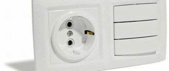
A typical example of combining a socket and a switch in one unit
Often in a corridor or hallway there is a need to combine a network connection point (socket) and a switch for several lighting groups. This method solves several problems:
- An extensive electrical outlet network in the corridor is usually not needed: there are no constantly used electrical appliances. However, there is a need to connect a vacuum cleaner or charger. In addition, a radiotelephone base unit can be installed in the hallway.
- There is little space on the walls in this room; there are wardrobes, a mirror, and a hanger. Part of the corridor is usually occupied by the input switchboard and metering device (meter). Therefore, compact placement of switching equipment is a key issue.
- By combining the socket and switch, wiring is saved and installation of an additional junction box is not required.
- If you additionally connect a second device: a switch to a socket, or vice versa, there is no need to damage the wall or organize a route for the power cable. The connection is made with minimal impact on the room.
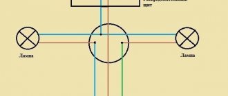
As can be seen in the illustration, to implement the entire circuit you will need one circuit breaker (in the panel it can be called “corridor: lighting, socket”), and one distribution box.
The zero bus N (blue color) passes through a kind of transit to the lighting groups and to the socket. The PE grounding is inserted into the socket body, and (if one of the lighting groups is in the bathroom) into the lamp body. The phase after the machine is connected to the socket through the distribution box. The disconnection occurs in the socket box. In this case, any terminal block is used: for example, WAGO.
A small section of wire connects the phase terminal in the socket and the input terminal of the two-key switch. Next, a phase is laid from the output terminals to each lighting group.
This scheme is usually used during design, since you still have to lay cables to different lighting groups. If such a solution is optional, you do not install additional boxes. The hole for the switch or socket box is made next to the already mounted device. All that remains is to install additional wiring.
If there is a need to connect the socket and lighting to different circuit breakers (for example, a power socket is used for a powerful electrical appliance), the phase is initiated along different power lines.
There is no need to use an additional distribution box; the phase wire passes through it in transit, without disconnection.
Tip: Leave a loop on each phase wire in the distribution box. With the future expansion of the network, you can cut the wiring and quickly organize the connection using the blocks.
In any case, this installation method saves both wiring and wall space. For example, let's look at the classic version of connecting a socket and switch to a distribution box.
Two cable routes were laid, the connection was in the junction box. Looking at the diagram, it becomes obvious that connecting the switch directly to the outlet is more efficient.
Connecting protection, control and lighting devices
Let's start by installing the lighting circuit protection device. For our example, a two-pole circuit breaker is used; the rating should be calculated for each individual case individually, since the lighting power will be different everywhere. In some places there will be only one 150 W lamp, and in other cases there will be several 3 kW spotlights.
The wire we use has double insulation, common outer and inner, separate for each core.
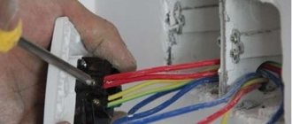
Carefully, without damaging the internal insulation of the cores, remove the outer layer. First, from the wire supplying the protection device.
Then, from the wire going to the junction box.
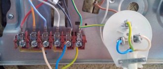
Now, we connect the two-pole circuit breaker.
We measure the length of wire required for connection. We bite off the excess. Then, remove the insulation from the wires and connect the wires to the terminals. The wire has a different color for each core.
- We define the blue core to transmit zero;
- Yellow with a green stripe - for grounding;
- We use the remaining core for phase transmission. In our case, the phase on the wire approaching the machine is white with a black stripe, and on the wire going to the junction box it is simply white.
When making connections, carefully ensure that the upper wires suitable for the machine match the colors of the lower ones. At the top, the phase is on the left, at the bottom there should be the same on the left. At the top, zero is on the right, so the bottom should be on the right.
We will not use grounding conductors in our example, but in principle, they can be used to transfer grounding to the corresponding contacts of the lamps. Unless, of course, it is structurally provided for in the electrical supply system of your home.
Many lamps have a metal body and are designed with a grounding contact. This is especially true in rooms with high humidity.
We isolate the unused grounding conductors and put them aside so that they do not interfere.
Let's move on to connecting the two-key switch.
We strip the wires and remove the outer insulation.
Next, we prepare the wire cores for connection. We remove 1 centimeter of insulation from each core.
Now, let's look at how to connect a double light switch.
Our example uses a switch with plug-in contacts.
We turn the mechanism with the back side. As you can see, it shows a wiring diagram for a specific switch. As a rule, such a scheme is found on all lighting control devices, but there are exceptions. Connecting two-key switches of various types is described in great detail in the instructions on how to connect a two-key light switch.
Following the symbols of the switch circuit, we connect the wires. In our case, “L” is the suitable phase, and the two arrows at the bottom of the phase are outgoing.
Let me remind you that in our example, we chose a white core for phase transmission. There is a corresponding contact for it on the switch; for a specific model it is designated by the letter “L”, a contact of a suitable supply phase.
We connect the two remaining strands of the wire to the outgoing contacts, on this model they are indicated by arrows, from them the phase, at the command of the keys, will be supplied to the lamp of the first or second room, or to both rooms at once.
The switch is connected. We install it in the socket box.
You can find out more about how to install other electrical wiring elements (sockets with and without grounding, double switches, including backlit ones, chandeliers, lamps, bathroom exhaust fans) here.
Let's continue. The lighting control element is installed, all that remains is to mount the lamps. In our example, they are presented in the form of two sockets with light bulbs.
We prepare the wires of the first and second lamps for connection. We remove the outer insulation, measure out the required amount of wire, and strip the core for connection. As a rule, lamps are equipped with standard plastic terminals; to connect through them you will need approximately 0.5 centimeters of bare wire strand
We connect the lamp of the first room, also known as a socket.
Then, the lamp of the second room.
Ground wires are not used in our example, so we isolate them.
And we put it aside so that it doesn’t get in the way.
All circuit elements are installed. Now, let's move on to the actual assembly of the circuit.
How to connect a single-key switch from an outlet
The classic option: a common zero bus from the distribution box is connected to a light point.
Grounding goes through the same cable channel (if used). But the phase wire does not go directly to the lighting fixture. A single-key switch (located in the same housing as the socket) breaks the circuit between the phase contact in the socket box and the light source. Quite a common scheme. Such a block can often be found in lighting stores.
Another application for such a module is a switchable socket. Let's say you have an electrical appliance that should be turned off at night or when leaving the room. This could be a router that distributes Wi-Fi. The unit itself is located high, so it is not always possible to use the standard power button. By clicking the switch key, you will de-energize the equipment without touching the circuit breaker in the distribution panel. Or, on the contrary: the device must be powered under certain conditions. For example, power supply for an alarm system.
In this case, the phase wire inside the block is simply opened by a switch, and the power wiring is connected as to a regular socket.
If the switch is being added to an existing outlet
Minimizing the consequences - replacing the socket with a block. The procedure itself is simple; we drill a hole nearby for the box and carefully install the new module.
There is no need to install a power incoming cable; it is already in the socket. But the output wiring, to the lighting device, will have to be extended. This is an individual decision, there is no universal way. The connection diagram is very simple: both the neutral and phase wires are laid not from the box, but from the socket box.
Naturally, you will have to install contact blocks. Although many connect the output wire directly to the socket contacts: some models allow such a connection.
If there are several sockets in a group, you can replace any of them with a common block (socket - switch). You simply choose a convenient location (from which you can run the wire to the lamp) and connect the switch to the outlet.
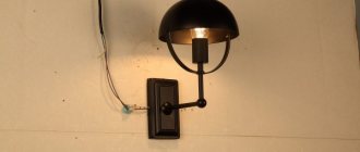
If you need to organize an additional light point in the hallway, you can use wall sconces. They are placed in close proximity to the outlet-switch block, and you do not have to destroy a large piece of the wall for wiring.
General safety rules
Of course, before starting such work (especially on a completed power supply system), you should de-energize the line and check that there is no voltage. Selecting a power cable will not cause any difficulties: a cross-section of 1.5 mm² is sufficient for organizing lighting. Since we are connecting the switch to the socket, and not vice versa, the primary (socket) cable will be more powerful: 2.5 mm².
Is it possible to connect an outlet to the switch?
Imagine the situation: you have renovated your premises, all the electrical wiring is walled up in the walls, and there are no backup boxes or socket boxes. An outlet needs to be installed in one of the rooms. Placing it next to the distribution box is irrational, the location is too high. But I don’t want to lay open wiring (especially, ditch the wall).
There is a switch in a convenient location that clearly has voltage. How to make a socket from a switch if it is possible to aesthetically place them next to each other?
To answer this question, let’s remember: what types of lighting schemes with switches are there?
Classic connection: tap from the distribution box.
The neutral conductor is inserted into the lamp from the box. In the box itself, a break in the phase cable is organized (it is opened using a switch), then the phase enters the lamp along the same path as the zero.
With this scheme, only the phase conductor is present in the body (installation box) of the switch. It will not be possible to organize a closed electrical circuit to connect an additional electrical appliance (via an outlet). You can use the phase from the switch, but you still have to lead the zero from the distribution box, which makes the idea pointless.
Conclusion: With this type of lighting arrangement, it is impossible to connect the socket to the switch.
The switch is located between the power source and the lighting fixture.
This scheme is less common, but in some rooms it is used. If at the design stage it was decided not to use distribution boxes in the lighting network, you are in luck. The switch wiring box contains both neutral and phase wires.
The sequence of work is as follows:
- We dismantle the existing switch without touching the installation box.
- We determine the routes for laying the input and output cables. If you have a diagram and plan for the electrical supply of the room, this is not difficult to do.
- Carefully drill a hole for the socket box.
- We install terminal blocks in the switch box and connect the socket according to the following diagram:
Safety regulations:
Since the current wiring is intended for lighting, most likely the cable cross-section is no more than 1.5 mm². The maximum possible load for such a cable (provided that it is copper): 3.3 kW. That is, not very powerful electrical appliances can be plugged into this outlet. The maximum is a vacuum cleaner. Well, phone chargers, a power supply for a router or an antenna amplifier - no problem.
Rules for installing distribution boxes
First of all, let's look at the rules for installing junction boxes. After all, the reliability of your electrical network depends on this. Moreover, these rules are quite logical and do not require major investments.
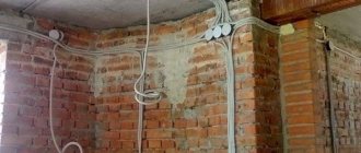
Location of distribution boxes in the apartment
So:
- First of all, remember that the junction box must be made of a material that matches the installation surface. So, on combustible surfaces, for example, wood, distribution boxes made of non-combustible materials should be installed. Usually it is metal.
- If the distribution box is mounted on a fireproof surface, for example, concrete, then boxes made of fire-resistant materials can be used. Usually, for these purposes, standard boxes made of special plastic are used, which are widely available in hardware stores.
- It is also worth remembering that, according to clause 2.1.22 of the Electrical Installation Code, a supply of wire must be provided at all branches and connections of conductors to ensure re-connection. The cost of following this rule will be mere pennies, but if it is necessary to reconnect, this reserve will become “golden”.
- It is also worth specifying the location of the distribution boxes. In general, it is not standardized, but they are usually located at the entrance to the room from the side of the door handle. The height of the distribution box is usually 10-20 cm from the ceiling. This allows you to protect it as much as possible from accidental touch and visually hide it.