to make a simple detector radio receiver with my own hands when I was thirteen years old. It was a homemade detector radio, assembled from a pine board, push pins and a few parts. A lot of time has already passed. My first detector receiver, of course, did not survive. But today, under the influence of nostalgia, I want to repeat that first school design of a detector radio without batteries .
What is a detector receiver - for those who don’t know.
For those who are hearing about a detector receiver for the first time, I’ll say right away that this is not a radio that will fill your room with music around the clock. Here are some of its features:
- — Yes, this radio works without batteries. :-). But…
- — A simple detector receiver will not be able to hear FM stations. The detector receiver only receives AM range stations - Medium, Long, and, if you're lucky, Short waves (MW, LW, HF).
- — The detector receiver is a night radio. Due to the characteristics of DV-SV-HF, normal reception is most often possible after dark. Do not attempt to assemble the detector receiver during the day unless you live near a radio station.
- — Sound volume of the detector receiver. It will be a barely audible “rustling” or, at best, a quiet sound comparable to a whisper.
- — Number of received stations. The detector receiver can only receive high-power or nearby AM radio stations. Therefore, most likely, at first you will be able to catch only one or two radio stations, “drowning” in the noise of interference.
- — The detector receiver requires special high-impedance headphones (headphones originally from the USSR with a resistance of 1600 Ohms or more). Although you can also use regular headphones from the player if you connect them through a matching transformer (see diagram below). Without such a transformer, you won’t be able to hear anything on simple headphones. You can also use piezo headphones.
- — The detector radio needs a good outdoor antenna and grounding . You may not be able to access these benefits in your apartment.
- — If all of the above doesn’t frighten you, then the good news: a detector radio receiver can theoretically work forever :-).
Detector simplest radio receiver: basics
The story touched on dental fillings for a reason. Steel (metal) is capable of converting ethereal waves into current, copying the simplest radio receiver, the jaw begins to vibrate, the bones of the ear detect the signal encrypted on the carrier. With amplitude modulation, the high frequency repeats the speaker's voice, music, and sound in scope. The useful signal contains a certain spectrum, which is difficult for a layman to understand; it is important that when adding the components, a certain law of time is obtained, following which the speaker of a simple radio receiver reproduces the broadcast. At the dips, the jaw bone freezes, silence reigns, and the ear hears the peaks. God forbid, of course, you should have a simple radio receiver.
The reverse piezoelectric effect changes the geometric dimensions of the bones according to the law of electromagnetic waves. A promising direction: a human radio receiver.
The Soviet Union was famous for launching a space rocket, ahead of the rest, for scientific research. Union times encouraged degrees. The luminaries have brought a lot of benefit here - designing radios - and earn decent money over the hill. The films promoted the smart, not the wealthy, it is not surprising that the magazines are full of various developments. A series of modern lessons on creating simple radios, available on YouTube, is based on magazines published in 1970. Let’s be careful not to deviate from traditions; we will describe our own vision of the situation in the amateur radio industry.
The concept of a personal electronic computer was developed by Soviet engineers. The party leadership recognized the idea as unpromising. Efforts have been devoted to building giant computer centers. It is too much for a worker to master a personal computer at home. Funny? Today you will encounter more amusing situations. Then they complain - America is shrouded in glory, printing dollars. AMD, Intel - have you heard? Made in USA.
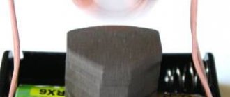
Everyone can make a simple radio receiver with their own hands. An antenna is not needed, there is a good stable broadcast signal. The diode is soldered to the terminals of high-impedance headphones (discard computer ones), all that remains is to ground one end. To be fair, let’s say the trick will work with the good old Soviet-made D2, the taps are so massive that they will serve as an antenna. We get the earth in the simplest radio receiver by leaning one leg of the radio element against a heating radiator that has been stripped of paint. Otherwise, the decorative layer, being the dielectric of the capacitor formed by the leg and metal of the battery, will change the nature of the operation. Try it.
The authors of the video noticed: there seems to be a signal, represented by an unimaginable jumble of rustles and meaningful sounds. The simplest radio receiver lacks selectivity. Anyone can understand and understand the term. When we set up the receiver, we catch the desired wave. Remember, we discussed the spectrum. The air contains a bunch of waves at the same time, you will catch the one you need by narrowing the search range. There is selectivity in the simplest radio receiver. In practice, it is implemented by an oscillatory circuit. Known from physics lessons, it is formed by two elements:
- Capacitor (capacitance).
- Inductor.
Let's take a moment to study the details; the elements are equipped with reactance. Due to this, waves of different frequencies have unequal attenuation as they pass by. However, there is some resonance. For a capacitor, the reactance in the diagram is directed in one direction, for an inductance - in the other, and the frequency dependence is shown. Both impedances are subtracted. At a certain frequency, the components equalize, and the reactance of the circuit drops to zero. Resonance sets in. The selected frequency and adjacent harmonics pass through.
The physics course shows the process of choosing the bandwidth of a resonant circuit. Determined by the attenuation level (3 dB below maximum). Let us present the theory, guided by which a person can assemble a simple radio receiver with his own hands. In parallel with the first diode, a second one is added, connected oppositely. It is soldered in series to the headphones. The antenna is separated from the structure by a 100 pF capacitor. Let us note here: the diodes are endowed with pn-junction capacitance, minds apparently calculated the reception conditions, which capacitor is included in the simplest radio receiver endowed with selectivity.
We believe we will slightly deviate from the truth when we say: the range will affect the HF or SV regions. Multiple channels will be received. The simplest radio receiver is a purely passive design, devoid of an energy source; one should not expect great achievements.
A few words about why we discussed remote nooks where radio amateurs crave experiments. In nature, physicists have noticed the phenomena of refraction and diffraction, both of which allow radio waves to deviate from their direct course. Let's call the first one rounding obstacles, the horizon moves away, giving way to broadcasting, the second - refraction by the atmosphere.
LW, SW and HF are caught at a considerable distance, the signal will be weak. Therefore, the simplest radio receiver discussed above is a touchstone.
What is heard on the detector receiver.
Previously, in my childhood (during the USSR, as well as perestroika), you could hear a lot of things on the detector receiver: “Deutsche Welle”, “Mayak”, “Voice of Russia” (Moscow Radio), “All-Union Radio”, “Leningrad Radio” " Unfortunately, Russian broadcasting is now being reduced on the CB band, but you can still hear Vesti FM. Foreign radio stations are still present on CB: “Radio Romania”, “International Radio of China”, “Transworld Radio”, “Polish Radio”, “Ukrainian Radio”. In general, if you want, you can find something.
What to do if you don't have the right diode?
The semiconductor diode performs the functions of a detector, so replacing it is problematic. But there are designs that can take on the role of a detector. And we are not talking about radio tubes or microcircuits. You can make a detector receiver from a blade and a pencil; they are placed instead of a diode. All other elements remain in place. You will also need a pin, this needs to be inserted into the back of the pencil. In this case, the two elements must be rigidly connected. The pencil is installed to the blade at an angle of 30-45 degrees.
The disadvantage of this “detector” is that you often need to sharpen the end of the pencil. And he won’t work with a stupid person. But this design is only for general development, and in case of an apocalypse, it will be much easier to use a diode. In the absence of a suitable one, you can easily install a transistor. You only need to use one pn junction in it. If you are reading this article, then most likely you know that there are pnp and npn type transistors. This is where you need to start, apply a signal from the oscillating circuit to the base, and remove the detected signal from the collector. A replacement semiconductor diode has been found, and now we can begin improving the design of the radio receiver.
What is it for.
What is it for? -But here’s why . Detector radio reception is now a rather serious hobby. At least in the west. People make antique detector receivers . This is understandable - they still have a lot of private and municipal low-power CB radio stations . Just a paradise for a fan of detector radio reception (probably, they have everything else there for people as well, and not just AM broadcasting - those bourgeois bastards... :-).
LUT, photoresist and debugging
After successful tests on a circuit board, we decided to create several more prototypes using the LUT method (and later using photoresist).
We also decided to improve the receiver by adding another sound amplifier to connect not only headphones, but also an external speaker. The choice fell on the PAM8403; it is a simple and inexpensive amplifier that requires a 5V power supply. The first prototype made using the LUT method looked like this:
LUT is a good thing for relatively quick prototyping at home, but when it comes to double-sided boards, things get tricky. The number of components on the board increased - for example, we decided to place a connector for the programmer on the board so that there was no need to remove the MK each time for flashing. So, the subsequent prototype became double-sided, was made using photoresist and began to look much nicer:
In the assembly:
The next step was to abandon the “add-on” components that we placed on the board using single-row PINs. So, it was decided to replace the amplifier with an LM386N and install a CD4050BE level converter. All this complicated the design, but the device began to look much better.
The final prototype we made at home looked like this:
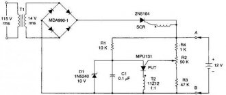
Detector receiver circuit.
shown here consists of four parts , an earphone, an antenna and a ground. The circuit differs from the classic circuit of a detector receiver in that an inductive variometer rather than a variable capacitor. Instead of a variable capacitor, a capacitor C1* with a constant capacitance is used. Selection of capacity is purely experimental. I applied C1 = 180 pf, which allows me to hear “Radio Romania”. Although, in principle, you can do without this capacitor altogether. Much has been written about the dangers of a variable capacitor in a detector receiver I will just say that indeed, this capacitor suppresses not only the interfering, but also the mainly useful signal. And in fact, it is needed in the detector receiver not to maintain oscillations in the circuit, but to “shift” the setting to a longer wavelength range when there is a lack of resource for adjusting the variometer coil. In other words, it is better to do without a variable capacitor at all, while ensuring good tuning by the variometer coil.
The simplest radio receiver with amplification
In the considered design of the simplest radio receiver, low-impedance headphones cannot be used; the load resistance directly determines the level of transmitted power. Let's first improve the characteristics using a resonant circuit, then supplement the simplest radio receiver with a battery, creating a low-frequency amplifier:
- The selective circuit consists of a capacitor and inductor. The magazine recommends that the simplest radio receiver include a variable capacitor with an adjustment range of 25–150 pF; the inductance must be made according to the instructions. A ferromagnetic rod with a diameter of 8 mm is wound evenly with 120 turns, covering 5 cm of the core. A copper wire coated with varnish insulation with a diameter of 0.25 - 0.3 mm is suitable. We provided readers with the address of the resource where you can calculate the inductance by entering numbers. The audience can independently find, using Yandex, and calculate the number of mH of inductance. The formulas for calculating the resonant frequency are also well known, therefore, while remaining at the screen, you can imagine the tuning channel of a simple radio receiver. The instructional video suggests making a variable coil. It is necessary to push out and push in the core inside the frame with wound turns of wire. The position of the ferrite determines the inductance. Calculate the range using the help of the program; YouTube craftsmen suggest that when winding a coil, draw conclusions every 50 turns. Since there are about 8 taps, we conclude: the total number of revolutions exceeds 400. You change the inductance in steps, and fine-tune the core. Let's add to this: the antenna for the radio receiver is decoupled from the rest of the circuit by a capacitor with a capacity of 51 pF.
- The second point you need to know is that a bipolar transistor also has pn junctions, and even two. It’s appropriate to use a collector instead of a diode. As for the emitter junction, it is grounded. DC power is then applied to the collector directly through the headphones. The operating point is not selected, so the result is somewhat unexpected; patience will be required until the radio receiver is perfected. The battery also greatly influences the choice. We consider the headphone resistance to be collector resistance, which determines the slope of the transistor's output characteristic. But these are subtleties, for example, the resonant circuit will also have to be rebuilt. Even with a simple diode replacement, let alone the introduction of a transistor. That is why it is recommended to conduct experiments gradually. And the simplest radio receiver without amplification will not work at all for many.
How to make a radio receiver that would allow the use of simple headphones. Connect via a transformer, similar to the one at the subscriber point. A tube radio differs from a semiconductor radio in that in any case it requires power to operate (filament filaments).
Vacuum devices take a long time to reach operating mode. Semiconductors are ready to accept immediately. Don't forget: germanium does not tolerate temperatures above 80 degrees Celsius. If necessary, provide cooling for the structure. At first, this is necessary until you select the size of the radiators. Use fans from a personal computer, processor coolers.
Detector receiver parts.
This detector receiver is a classic in school instrument making. It is assembled on a wooden pine block and push pins. When soldering the receiver on such a board, a nostalgic pine-rosin “tube” aroma is felt - a very important component. As in childhood.
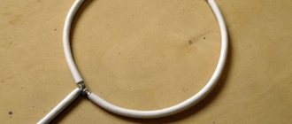
The detector receiver coil is wound on a plastic water pipe and contains approximately 90 turns (until the entire length is filled). To tune the receiver, a piece of ferrite rod from a Selga radio receiver is inserted inside the coil. That is, this detector receiver is configured with a variometer .
Capacitor C1* - as mentioned above - 180 pF. Although it may be of a different denomination. Or you can do without it altogether, if you can receive some radio station.
Capacitor C2 can be 1000 - 2200 pF. Not critical.
Diode D1 - the best diode for a detector receiver is D18 or D311 . But any other high-frequency germanium detector diode can be used. For example D9. Although the sound will be a little quieter. In general, diodes for the detector receiver need to be selected - see below.
Details
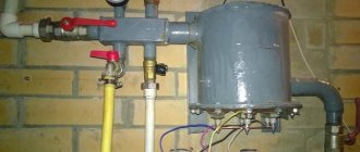
Grounding for detector receiver
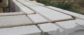
If you plan to ground through batteries or water pipes, then you should first wipe off the layer of decorative coating from them, which will interfere with effective operation.
A simple piece of pipe or fittings up to a meter in length, driven into the ground, can also serve as grounding. An iron plate buried in the ground to a depth of half a meter will have a similar effect, and the more metal surface, the better. In general, any metal object buried or firmly anchored in the ground can be used for grounding.
IMPORTANT: in hot weather, it is necessary to additionally moisten the place where the grounding pin is located with water, so the contact of the metal with the ground will be more reliable.
Creating an Oscillatory Circuit
Assembling the device
- inductors,
- variable and constant capacitor (it is better to use those made of paper or foil than ceramic ones),
- semiconductor diode type D9 (can be seen on a diode of any other type, the main thing is that it is based on a silicon crystal and high-frequency),
- High impedance headphones,
- Switching means – alligator clips, sockets, plugs, etc.
Assembling all these elements is not difficult; you can even do without soldering. It is enough to use the simplest circuit for assembling a detector receiver.
Assembling an additional amplifier for low frequencies
IMPORTANT: such amplifiers get very hot, so it is necessary to use additional cooling radiators.
Additionally, it is worth installing a high-frequency amplifier; it will help increase the amplitude of the signal without losing its shape. It can be made in the same way as a low-frequency amplifier using a single transistor. It is worth giving preference to field-effect transistors.
Installing the power supply
The power source can be batteries, a network, a solar battery, or a ready-made power supply from any household appliance, for example a DLS modem or a television antenna amplifier. You should avoid using phone chargers as a battery, as they operate pulsed.
I hope that this article will help you fulfill your childhood or no longer a child’s dream and assemble a radio receiver with your own hands. Moreover, this will not require any scarce parts from you, organization of the workplace, and the design parts themselves can be improved and replaced with more suitable ones at any time.
What kind of lighting do you prefer?
Built-in Chandelier
Expert opinion
It-Technology, Electrical power and electronics specialist
Ask questions to the “Specialist for modernization of energy generation systems”
DIY radio made from scrap materials. For example, to receive a station at 106.2 MHz in the FM band, the local oscillator frequency must be 95.5 MHz, leaving 10.7 for further processing. Ask, I'm in touch!
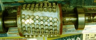
Selection of diodes for a detector receiver.
The sound volume of the detector receiver directly depends on the type and quality of the selected detector diode . Even diodes of the same name can produce different volumes. Therefore, it is necessary to select the diode by ear, on a working detector receiver. Using a switch, the two diodes are manually quickly switched, and thus the “winner” diode in terms of volume is determined. Next, the winner is placed against the next “contender” and the “winner” diode is again determined. And so on until the loudest “champion” diode is determined.
Excellent results in terms of volume in a detector radio are shown by diodes D311 and D18. And as it turned out, the classic D9 is not the best option compared to the D311 and D18.
Settings
The receiver is quite unpretentious and, if assembled correctly, starts working immediately. However, there are a number of general recommendations for setting it up.
- After switching on, check that the lamps are glowing. If there is no filament, then you should check the serviceability of the lamp or look for an open/short circuit in the filament circuit. The heater filaments of the heated lamp should glow orange.
- The presence of anode voltages should be checked. Some voltages are indicated in the diagram.
- Check the operating mode of the lamps by setting the required voltages in the cathode circuit. If the deviations are significant (more than 50%), appropriate resistors should be selected.
- Check the operation of the ULF: when you touch the resistor motor with your finger, you should hear a characteristic noise in the speaker. It is more difficult to check the operation of the amplifier without an oscilloscope, but if the voltages are set correctly and there are no errors during assembly, it will work.
- Check the operation of the mixer. When you rotate the mixer operating mode control knob at the point where generation begins, noise should appear in the speakers.
- Check the UHF operation: when you touch the antenna input with a screwdriver, characteristic clicks are heard in the speakers.
It is strictly not recommended to touch live circuit elements, as this may result in electric shock! This is dangerous to life and health.
If everything works, then using the mixer mode adjustment knob we get the appearance of noise in the speakers, after which we tune in to the radio station using a variable capacitor. Then, by more precise adjustment of the mixer mode and frequency, we achieve the best reception quality. The setting indicator helps with this. All! You can enjoy warm tube sound. The sound quality of this receiver turned out to be quite good, in any case, it cannot be compared with the sound quality of the super-regenerator.
And finally, the most interesting thing, the reason for which everything was started, is the signal oscillograms at different points of the circuit. I don’t have oscillograms of the mixer’s operation due to the fact that the oscilloscope probes greatly influence its operating mode, so let’s start with the amplifier.
RECOMMENDED: Receiving and decoding signals from space
Let's consider the signal at the input and output of the first stage of the amplifier. The oscillogram of the input (bottom) signal shows that, in addition to the IF signal, high-frequency noise passes from the mixer, and its amplitude is even greater than the amplitude of the desired signal. But this is not a problem, since it will be filtered by the passband of the cascade. Indeed, only the IF signal with an amplitude of about 200 MV is visible in the output signal oscillogram. Please note that the oscillograms have different scales. From these oscillograms you can see that the actual stage gain is about 30 versus the calculated 80.
Signal at the input and output of the first stage of the amplifier
Already at this point, using an oscilloscope, you can see the tuning to the station, which looks like an increase in the amplitude of the signal and a pulsating change in its frequency (frequency modulation).
Frequency modulation of the IF signal
Next, let's look at the operation of the second cascade of the amplifier. Everything is simple and clear here, the input signal is amplified by about 30 times, and at the output we already get about 5 V.
Signal at the input and output of the second stage of the amplifier
After the second stage, the signal enters a limiter, in which it is further amplified and the amplitude is limited at 70 V. Here you can clearly see the suppression of parasitic amplitude modulation and an almost square wave at the output.
Signal at the input and output of the limiter
You can also look at frequency modulation here.
Frequency modulation in the limiter
Now let's take a look at the oscillograms of the counting detector. It can be seen that at each rising edge of the signal, a pulse of approximately the same duration and amplitude is regenerated from the limiter.
Pulses in the counting detector
Frequency modulation is also clearly visible here. For example, changing the frequency of the input signal changes the pulse repetition rate at the detector output.
Pulses in the counting detector
Then the pulses go to an integrating RC circuit, which leads to the formation of a low-frequency output signal. The oscillogram clearly shows the effect of frequency modulation on the output signal.
Generating a sound signal
In total, the operation of the detector looks as shown in the figures below. Here you can see that the audio signal is somewhat delayed relative to the modulated IF, this is due to the integrating RC chain.
Operation of the FM detector
From the detector, the signal goes to the first ultrasonic stage, where it is amplified, and in addition, residual noise from the detector is filtered out.
Operation of the first ultrasonic stage
We can stop there.
Antenna and ground for detector receiver.
The antenna for the detector receiver is a wire of 20 - 40 meters, stretched on the street between houses or trees. And the higher, the better. But living in an apartment, not everyone can have such an antenna. You can, of course, hang a piece of wire around the inner perimeter of the apartment, but there is no guarantee that such an antenna will work with your detector receiver. Reinforced concrete walls significantly dampen the useful radio signal.
And one more thing - do not try to assemble the detector receiver during the day. Even with a good antenna, during the day, in urban areas, at best, only the hum of interference will be heard. Although exceptions are possible if there is a powerful CB radio station nearby or a local underground CB transmitter ;-).
I also don't always have access to a good antenna. Living in a high-rise building, in the summer I simply run an 8-meter wire out the window. This is enough to hear the powerful “Radio Romania” at night and some other “Bakhhal - Makhkhal - Bukhhall”.
Grounding for the detector receiver - using a radiator. This is not the best grounding, but in a high-rise building you don’t have much choice. The heating battery “catches” a lot of interference. Therefore, I connect through a filter - a regular 3.9 kOhm resistor. Oddly enough, this completely reduces the interference in the form of hum - a clean signal appears in the headphones!
Prototype on circuit board
My friend, the talented engineer Konstantin Tomarevsky, supported the idea, and we began to think about how to make the first prototype.
The idea was to create an FM receiver that could be controlled via an MK. The first prototype was assembled on the assembly line, and it became clear that it works
For the very first version, the following components were selected:
1. MK Atmega328P-PU 2. RDA5807M 3. Nokia 5110 display
Such a microcontroller is used in Arduino UNO; accordingly, our device is compatible with UNO at the hardware level.
RDA5807M is the “heart” of our designer. This tuner has the following features:
- CMOS technology - Monolithic package, does not require external components (almost) - Frequency band: 50-115 MHz - Channel pitch - from 200 to 25 kHz - RDS/RBDS - ADC and built-in frequency synthesizer - Adaptive noise reduction - Digital interface ( I2C) - Signal level (RSSI) - Amplifier - Audio volume control
Nokia display is black and white, 84x48 pixels. It is very easy to connect and control.
After soldering on the circuit board it turned out something like this:
It was decided to use Bootloader from Arduino, this made it possible to maintain compatibility with all numerous libraries and significantly reduce the entry barrier for those who already had some experience with the platform. The user interaction interface is implemented as follows. Three buttons connected to the analog input of the MK through resistors are used to switch modes and control the receiver. Another button is used to reboot the MK. The screen accordingly displays information about volume, station, etc.
Headphones or headphones?
This design has earned popularity among novice radio amateurs for a reason. It contains a minimum number of elements, but allows you to receive signals from powerful stations. Unfortunately, only for high-impedance headphones. Headphones with a 3.5 mm plug, which are used for computer equipment or phones, are not suitable - you will not be able to listen to the signal. It is necessary to use TON-2 headphones. They have a winding resistance of about 1600 Ohms.
But one feature should be noted - if you have computer speakers with an amplifier, they can be connected to the receiver output. Then you won’t have to look for TON-2 headphones, which have already become in short supply.
Let's start assembly
To make a simple radio with your own hands, it is enough to have basic skills. You don't have to use a soldering iron. But if you use it, then the installation of the structure will look better hanging. The largest element is the variable capacitor. Moreover, you need to use those in which air acts as a dielectric. Modern film capacitors are not suitable for use in the design of a detector receiver.
Select a suitable housing for the structure. Due to the fact that the coil has large dimensions, the housing will be appropriate. But you can reduce the size of the coil; to do this you will have to increase its inductance. This can be done very simply - wind the wire not on a thick frame, but on a ferrite core. Then the entire structure can be placed in a small case, on which it is necessary to install jacks for connecting headphones, grounding and an antenna.
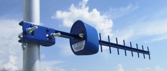
The process of making a homemade antenna
At the initial stage, you need to select the necessary tools, without which you will not be able to make a device for fm radio on your own.
From a large number of methods, you can choose the most suitable one, taking into account your own strengths and capabilities.
We recommend reading: Thyristors: principle of operation, testing and characteristics
On a note! The manufacture of an antenna in this case is discussed using one of the examples of creating high-quality antennas that can be used for any household radio receivers.
Tools:
- Solder, rosin, soldering iron and soldering flux;/.
- Thin copper wire.
- Dielectric base - for example, chipboard sheets, boards, etc.
- Fasteners - nuts, screws, screws and others.
- Suitable coaxial cable and plug.
- Standard locksmith tool.
- Waterproof paint or varnish.
How to make an antenna based on a finished drawing:
- The wire is given the required shape.
- Taped to a dielectric base.
- Solder the cable.
- The braid is connected to one end of the device, the central core to the other.
- The cable and dipole antenna are connected in the same way.
- The device is painted.
- After the paint has dried, the antenna is installed on the pipe, the cable on the support.
- The other end of the cable is connected to the plug and the antenna is raised as high as possible.
The simplest FM antenna for a DIY receiver
The description describes a method for making a loop antenna. Other devices differ in shape and materials, but the principle of operation is the same for all.