Features of phase and zero designation
In order to independently install and connect various types of electrical equipment: lamps, sockets, automatic machines, electric stoves, boilers and others, you need to understand the designation of phase and zero for switching: L (phase), N (zero), PE (grounding). State standards and electrical safety regulations establish designation rules, which simplifies the determination of the functional purpose of the cores during installation so that the connected device can function correctly.
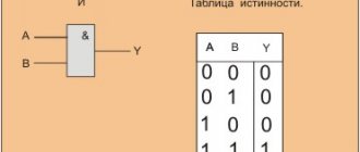
Phase and zero designation
For the safe organization of power supply in the residential and industrial sectors, the connection of electrical circuits is carried out with insulated cables with internal conductors that differ in the letter and color marking of the insulating coating. The L marking in electrics helps installers perform repair and assembly operations faster and without errors. Electrical installations with voltages up to 1000 V belong to the domestic sphere of operation; the rules for designating electrical wires are regulated by GOST R 50462/2009. Before carrying out any work on electrical equipment, you need to know how phase and zero are indicated on the diagram.
The phase designation (L) identifies the live AC conductor. The English word “phase” is translated as “active wire”. Phase lines pose an increased danger to people and household property, therefore, in order to ensure the safe operation of electrical equipment, they are covered with insulation of different colors. Wires must be marked for proper connection with the required clamps/terminals. In the case of connecting three-phase networks, digital markings L1/ L2/ L3 are provided.
The N designation is derived from the abbreviation of the English word “neutral” - neutral. This is how the neutral wire is marked in the world. Although many masters believe that its letter designation is taken from the English “NULL” - zero.
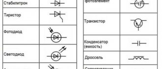
Color and letter designation
Before starting installation work, the electrician must clarify the designations L and N in the electrical diagrams and be sure to adhere to them. State standards in electrical engineering establish phase/zero designations in accordance with GOST R 50462/2009, which obliges manufacturers to place L-cores in insulation painted brown or black, PE-cores in yellow-green. For the N-wire, a standard color is used - light blue or a blue base with a white stripe.
Electrical marking is applied regardless of the number of cores in the bundle. PE and L conductors may also differ in thickness, with the former being thinner, especially in cables used to power portable electrical equipment. Experts recommend using the same color of cores when you need to branch one phase from a 3-phase one. Manufacturers can use a variety of color markings for phase switching according to the circuit, but there is a ban on adjacent colors blue, green and yellow.
The designation of phase and zero in English has been adopted by EU standards and is present on all European electrical appliances. In 2004, changes were made to the color identification of conductors as part of the EC Standards amendment No 2:2004 to BS 7671:2001. Single-phase installations use the traditional colors of red and black for the phase, with the neutral conductors being replaced by the colors brown and blue (Regulation 514-03 -01). The protective conductors remain green and yellow.
Important! All devices after March 31, 2004 and before April 1, 2006 can be installed in accordance with Amendment No. 2: 2004 or Amendment No. 1: 2002, in other words, they can use the harmonized colors or the old colors, but not both.
International sizes
In the world, sizes indicated by letters of the English alphabet are considered more common. These are the XS, S, M, L, XL, XXL, XXXL that are familiar to all of us. Clothes smaller than XS are considered children's, and clothing larger than XXXL begins its own size chart. The most common are women's sizes S, M, L - the golden mean, as they say.
We indicate in the table what volumes international sizes correspond to.
| international | XS | S | M | L | XL | XXL | XXXL | |
| chest girth | 80 | 84 | 88-92 | 96-100 | 104 | 110 | 116 | |
| waist circumference | 60 | 66 | 70-74 | 78-82 | 86 | 92 | 98 | |
| hip girth | 86 | 90 | 98 | 102-106 | 110 | 116 | 122 | |
But do not forget that even generally accepted standards can allow several centimeters of error.
Often there is a problem with converting size L to Russian women's. This also applies to other sizes. This happens because Slavic countries have adopted a slightly different system for measuring clothing. For Ukraine and Russia, the most common sizes are from 40 to 58. Mostly all models of women's clothing are produced with such size designations. You will have to look for things larger or smaller than the proposed range in special stores.
It’s very simple to compare Russian sizes with international ones - let’s line up the first and second ones in order and get the following result:
- XS – 40;
- S – 42;
- M – 44-46;
- L– 48-50;
- XL – 52;
- XXL – 54-56;
- XXXL – 58.
This is the norm for all manufacturers, but very few of them adhere to the above rules. That is why in any store and with all manufacturers it is better to check the dimensions in centimeters or inches (for reference: 1 inch = 2.54 cm).
Plus and minus symbol
The standards used will vary depending on what country the wiring is in, the type of electricity, and other factors. Learning about the different options that can be used in a given situation is important for workplace safety.
When connecting to a DC source, 2 or 3 wires are usually used. The coloring looks like this:
- Red - “+” plus wire;
- Black - “-” minus wire;
- White or gray - ground wire.
Note! Reliable and legible markings must be provided at the interface where new and old versions of the fixed wiring color code exist. The warning notice must also be prominently displayed on the relevant switchboard controlling the circuit.
Zero phase check
Not all manufacturers comply with the requirements for network marking; in addition, old cables from “Soviet times” do not have it at all, which does not allow us to first clarify the purpose of the cores. In order to correctly install electrical equipment in this case, for example, a socket, the designation is clarified using an instrument method and the connection points are marked manually with a heat-shrinkable tube.
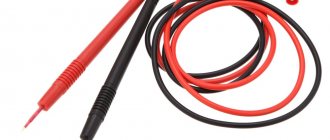
When performing phase/zero testing, safety precautions must be taken; it is not recommended to carry out this work by personnel not trained in the rules of safe operation of electrical installations, since if they are not followed, a person may be fatally injured by electric shock, in this case it is better to invite a qualified electrician. The multimeter can test voltage, resistance and current. This is an ohmmeter, voltmeter and ammeter in one device.
Preparing an electric multimeter for measurements:
- Set True RMS to “AC” or “V” with a wavy line, select the approximate voltage to be tested.
- Insert the black probe into the common (COM) port of the meter, and the red probe into the test port.
- When conducting tests, make sure that your hands will not come into contact with a live electrical circuit or a metal sensor. Only touch the plastic or insulated probe handles.
3-phase network testing template:
- Place the black probe on phase 1 and the red probe on phase 2. Read and record the voltage between phases 1 and 2.
- Then leave the black probe on phase 1 and move the red one to phase 3, and also record the voltage between phases 1 and 3.
- Place the black probe on phase 2, and the red probe on phase 3, monitor the voltage between phases 2 and 3.
- All three branches are averaged by adding the total voltage and dividing by three to find the operating voltage.
- Make sure that all three-phase voltages are within 3%.
L and N in electrics - color coding of wires
The vast majority of cables have different colors of core insulation. This was done in accordance with GOST R 50462-2009, which sets the standard for ln marking in electrical installations (phase and neutral wires in electrical installations). Compliance with this rule guarantees fast and safe work for a technician at a large industrial facility, and also allows you to avoid electrical injuries during independent repairs.
Variety of colors of electrical cable insulation
The color marking of wires is varied and varies greatly for grounding, phase and neutral conductors. To avoid confusion, the PUE requirements regulate what color ground wire to use in the power supply panel, and what colors must be used for zero and phase.
If the installation work was carried out by a highly qualified electrician who knows modern standards for working with electrical wires, you will not have to resort to using an indicator screwdriver or a multimeter. The purpose of each cable core is deciphered by knowing its color designation.
Markings on the body
Designations on the switch housing
In addition to the L designation on the lighting switch, there are other symbols and icons near its working contacts or on the housing.
Most often, manufacturers use the symbolic principle of marking the two states of a switching device - on and off. The intuitive zero and one (“0” and “1”) are traditionally used as such symbols. The first of them corresponds to the “Off” or OFF state and is located in the lowest zone of the body of the electrical device. The second icon means “Enabled” (ON) and is located at the top. There are also such rare symbols as arrows indicating the direction of commutation.
Having become familiar with what L is on a room lighting switch, anyone can independently connect it to an existing electrical network. In case of emergency, you can repair a faulty device. This will also be helped by the ability to understand the differences in markings for different types of switches produced by different manufacturers.
Ground wire color
From 01/01/2011 the color of the grounding (or grounding) conductor can only be yellow-green. This color marking of wires is also observed when drawing up diagrams on which such conductors are signed with the Latin letters PE. The coloring of one of the conductors on cables is not always intended for grounding - usually it is done if there are three, five or more conductors in the cable.
PEN wires with combined “ground” and “zero” deserve special attention. Connections of this type are still often found in old buildings, in which the electrification was carried out according to outdated standards and has not yet been updated. If the cable was laid according to the rules, then blue insulation was used, and yellow-green cambrics were put on the ends and joints. Although, you can also find the color of the grounding (grounding) wire exactly the opposite - yellow-green with blue tips.
Protective grounding is mandatory when laying lines in residential and industrial premises and is regulated by PUE standards and GOST 18714-81. The neutral grounding wire should have as little resistance as possible, the same applies to the grounding loop. If all installation work is carried out correctly, then grounding will be a reliable protector of human life and health in the event of a fault in the power line. As a result, correctly marking cables for grounding is critical, and grounding should not be used at all. In all new houses, wiring is done according to the new rules, and old ones are put in line for replacement.
Colors for neutral wire
For “zero” (or zero working contact) only certain wire colors are used, also strictly defined by electrical standards. It can be blue, light blue or blue with a white stripe, regardless of the number of cores in the cable: a three-core wire in this regard will be no different from a five-core wire or with an even larger number of conductors. In electrical circuits, “zero” corresponds to the Latin letter N - it participates in closing the power supply circuit, and in circuit diagrams it can be read as “minus” (phase, respectively, is “plus”).
Colors for phase wires
These electrical wires require especially careful and “respectful” handling, since they are live, and careless touching can cause severe electric shock. The color marking of wires for connecting a phase is quite varied - you cannot use only colors adjacent to blue, yellow and green. To some extent, it is much more convenient to remember what the color of the phase wire may be - NOT blue or cyan, NOT yellow or green.
On electrical circuits, a phase is designated by the Latin letter L. The same markings are used on wires if color markings are not used on them. If the cable is intended to connect three phases, then the phase conductors are marked with the letter L with a number. For example, to draw up a circuit for a three-phase 380 V network, L1, L2, L3 were used. In electrical engineering, an alternative designation is also accepted: A, B, C.
Before starting work, you need to decide what the color combination of wires will look like and strictly adhere to the chosen color.
If this issue was thought through at the stage of preparatory work and taken into account when drawing up electrical wiring diagrams, you should purchase the required number of cables with cores of the required colors. If you still run out of the required wire, you can mark the wires manually:
- ordinary cambrics;
- heat-shrinkable cambrics;
- electrical tape.
About the standards for color marking of wires in Europe and Russia, see also this video:
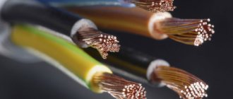
Types of wires
When connecting electrical equipment and installing various systems, you cannot do without special conductors. They are made of aluminum or copper. These materials conduct electricity well.
Important! Aluminum wires must only be connected to aluminum wires. They are chemically active. If they are connected to copper, the current transmission circuit will quickly collapse. Aluminum wires are usually connected using nuts and bolts. Copper - through a terminal. It is worth considering that the latter type of conductors has a significant drawback - it quickly oxidizes when exposed to air.
Advice in case the current stops flowing at the point where oxidation occurs: to restore the power supply, the wire must be insulated from external influences using electrical tape.
Letter marking of wires
For household and industrial power lines, insulated wires with internal conductors are used. Products differ depending on the color of the insulating coating and markings. The designation of phase and zero in electrics speeds up repair and installation work.
Marking of cables in electrical installations under voltage up to 1000 V is regulated by GOST R 50462-2009:
- in clause 6. 2.1 it is indicated that the neutral conductor is marked as N;
- clause 6.2.2. states that the protection wire with grounding is designated PE;
- in paragraph 6.2.12 it is said that in electrics L is a phase.
Understanding the markings simplifies installation work in commercial, residential and administrative buildings.
L – phase designation
In an AC network, there is a live phase wire. Translated from English, the word Line means an active conductor, line, and is therefore marked with the letter L. Phase conductors must be covered with colored insulation, since, being exposed, they can cause burns, human injuries, fire or failure of various equipment.
N – alphabetic symbol of zero
The sign of a neutral or neutral working cable is N, from the abbreviation of the terms neutral or NULL. When drawing up a diagram, the zero switching terminals in a single-phase or three-phase network are marked this way.
The word “zero” is used only in the CIS countries; throughout the world the core is called neutral.
PE – grounding index
If the wiring is grounded, the letter marker PE is used. In English, the meaning of Protective Earthing is translated as grounding wire. Clamps and contacts for switching with ground zero will be designated similarly.
Connection features
Contacts of a two-key switch
To understand the connection features of a standard switch, you will need to study the principle of its operation. As an example convenient for description, a type of device with one key was chosen.
- the switch is always installed in the gap of the phase wire, the second end of which is led either to the junction box or directly to the lamp;
- there are only two wires on both sides, each of them intended for its own purposes;
- one of them is laid to the switch from the linear machine and is constantly energized;
- it is missing on the second wire, which is why the lighting fixture connected to the switch does not light up.
Mains 220 Volts are supplied to it only after pressing a button or key when switching it to the “On” mode. After this, a working lamp or light bulb immediately lights up.
When connecting a three-key switch, the distribution of functions of each of the contacts is the same. But in this case, on the side of the conductor outlet to the junction box or chandelier, there are two contacts that serve for switching different groups of light bulbs. Accordingly, the number of designations increases by one. The same thing is observed when using a three-key product, in which the number of contacts and outlet conductors increases by another unit. Knowing these features of the switching device will help you decipher the L marking on the switch.
Conductor insulation coating colors
It is necessary to color-code grounding, phase and neutral cables in accordance with the requirements of the PUE. The document establishes color differences for grounding in the electrical panel, as well as for zero and phase. Understanding the insulation color code eliminates the need to decipher letter markers.
Ground wire color
In the Russian Federation, the European standard IEC 60446:2007 has been in force since January 1, 2011. It notes that the grounding has only yellow-green insulation. If an electrical circuit is drawn up, the ground should be designated as PE.
There is a grounding core only in cables with 3 cores.
PEN conductors used in old buildings combine ground and neutral conductors. The insulating coating in this case has a blue grounding color and yellow-green cambrics at the connection points and ends of the wire. In some cases, the reverse marking was used - yellow-green color zeroing with blue tips.
The ground and neutral conductors of PEN cables are thinner than the phase conductors.
The organization of protective grounding is a prerequisite for creating an electrical network in residential and industrial buildings. Its necessity is indicated in the PUE and GOST 18714-81. Standards state that zero grounding should have the lowest resistance. To avoid confusion, use color markings for the cables.
Color designation of zero working contacts
In order not to confuse where the phase is and where the zero is, instead of the letters L and N, they are guided by the colors of the cables. Electrical standards note that the neutral is blue, light blue, blue-white, regardless of the number of wires.
Size L - what size is women's?
The generally accepted size L (“L”) for the fair half is as follows: chest girth – 96-100 cm, waist line – 78-82 cm, hip girth – 102-106 cm. But it is important to remember that Europe sews clothes somewhat larger, and Asian countries are slightly less than normal.
Size L - what size is Russian women's? In principle, most of our clothing manufacturers adhere to the generally accepted measurement system, therefore, based on the above volumes for size L, you can safely take things for yourself without trying them on.
Size L - what size is women's for Europe? Some features appear here: firstly, the clothes will be a little larger, and secondly, it is very important to take into account height - this will also change the overall size of the selected item of clothing. The German L-coy, for example, denotes clothing for tall girls whose height is more than 172 cm.
For America there is a separate size chart; all volumes and sizes are indicated in inches. Answering the question: “L is what size of women’s clothing in the USA?” - we get the answer: “14-16”.
Each country has its own accepted measurements, therefore, when choosing goods in foreign stores, you should carefully study the sizes offered there and only after a thorough check make any purchases.
The nuances of manual color marking
Manual marking is used when using wires of the same color in old buildings. Before starting work, a diagram with the color values of the conductors is drawn up. During the installation process, you can mark current-carrying conductors:
- standard cambrics;
- cambrics with heat shrinkage;
- insulating tape.
The rules allow the use of special marking kits. The installation points for markers to indicate zero and phase are indicated in the PUE and GOST. These are the ends of the wire and where it connects to the bus.
Specifics of marking a two-core wire
If the cable has already been connected to the network, you can use an indicator screwdriver. The difficulty in using the tool lies in the inability to determine multiple phases. You will need to test them with a multimeter. To prevent confusion, you can color-code the electrical conductor:
- choose heat-shrinkable tubes or electrical tape to indicate zero and phase;
- work with conductors not along their entire length, but only at the junctions and joints.
Three-wire wire marking
To search for phase, ground and zero in a three-wire wire, it is advisable to use a multimeter. It is set to alternating voltage mode and carefully touches the phase with probes, then touches the remaining cores. The tester's performance should be recorded and compared. In the phase-ground combination, the voltage will be lower than in the phase-zero combination.
After clarifying the lines, you can make markings. The corresponding colors will help you understand whether the phase is L or N. For zero it will be blue or blue, for plus it will be any other.
The procedure for marking a five-wire system
Electrical wiring from a three-phase network is carried out only with a five-core cable. Three conductors will be phase, one will be neutral, one will be protective ground. Color coding is applied in accordance with regulatory requirements. For protection, a yellow-green braid is used, for zero - blue or cyan, for phase - from the list of permitted shades.
How to mark combined wires
To simplify the wiring process, cables with two or four cores are used. The defensive line here connects to the neutral. The letter index of the wire is PEN, where PE denotes the grounding conductor, and N is the neutral conductor.
According to GOST, special color markings are used. The length of the combined cable will be yellow-green, and the tips and connection points will be blue.
Highlight the main points of problem areas with cambrics or electrical tape.
How to choose the right size?
To find out your size, you need to measure the basic parameters. These are chest circumference, waist, hips, shoulder width, sleeve length in cm. The correctness of the result depends on the accuracy of your actions. Let's look at how to measure your body correctly.
- To measure the circumference of the chest, you need to firmly place the meter from the back, pass it through the armpits to the most protruding points of the chest.
- We measure the waist at its thinnest (narrowest) part.
- The hips need to be grasped so that the most protruding points of the buttocks (the widest part of the thigh) fall.
- Shoulders are very easy to measure - a straight line from one shoulder to the other.
- It is correct to measure the length of the sleeve using your arm slightly bent at the elbow. The top point is where the shoulder connects to the arm, the bottom is the wrist.
Since there is no single sizing system in the world, in each store you choose, you must first look at the size chart offered there, then compare the measurements obtained with those indicated in the table, and only then select items for your volumes. Once you know your exact measurements, you can confidently buy clothes online.
Wiring colors as a way to speed up installation
Before GOST R 50462-2009 came into effect, cables were marked white or black. The phase and zero were determined when the control switch was turned off at the moment of power supply.
The use of color markers simplifies repair work, ensures safety and convenience. Based on the shade of the cables, the master will not spend much time connecting electricity to a house or apartment.
You can consider the meaning of color marking using the example of a lamp. If the lamp is changed and the zero and phase are reversed, there is a risk of injury or death from electric shock. When in electrics the designation L and N is made by color, the phase will go to the switch, and zero will go to the light source. The voltage will be neutralized, and you will be able to touch even a light bulb that is on.
How the output contacts are connected
The presence of a large number of symbols on the contacts of multi-key electrical switches causes certain difficulties with their connection. It is difficult for an inexperienced user without measuring equipment to determine which of the conductors is responsible for turning on a specific light bulb in a chandelier or one of the groups of luminaires. In this situation, you have to act by trial or error.
The procedure for each type of switch can be represented as the following algorithm:
- with a single-key version, the switch has L and L1 - this means that only one outlet conductor is connected to the output;
- in a two-key analogue, they will have to be connected alternately to each of the output terminals, and watch which of the illuminators lights up. Based on experimental data, the desired contacts are selected under the designations L1 and L2;
- in a three-key model, the possibilities expand: you will have to go through the connection order many times (the number of combinations of three options is 6).
Single-key switches
Two-gang switches
Three-key switches
It is possible to simplify the last operation if you alternately connect “unidentified” outlet conductors with the phase wire and observe which light bulbs, groups or lamps light up.
Each time after connecting the next wire and identifying a group of illuminators, this tap is connected to the terminal selected specifically for the consumer being tested. After this, the control function of this circuit is automatically transferred to the key whose switching mechanism is connected to this contact.