Temperature sensors
Temperature sensors are among the most commonly used sensors. Temperature sensors are used by all types of equipment, ranging from computers, cars, kitchen appliances, air conditioners and (of course) home thermostats. The five most common types of temperature sensors include:
- thermistors;
- thermocouples;
- RTD (resistive temperature sensors);
- digital thermometer chips;
- analog thermometer microcircuits.
This article will provide you with a brief introduction to each of the sensor types listed.
Thermistor
As the name suggests, a thermistor (i.e., thermistor) is a temperature sensor whose resistance varies with temperature.
Thermistors are available in two types: PTC (positive temperature coefficient) and NTC (negative temperature coefficient). The resistance of a PTC thermistor increases with increasing temperature. An NTC thermistor, on the other hand, decreases in resistance as temperature increases, and this type appears to be the most commonly used type of thermistor. See Figure 1 below.
Figure 1 – Graphic symbols of PTC and NTC thermistors
It is important to understand that the relationship between a thermistor's resistance and its temperature is very nonlinear. See Figure 2 below.
Figure 2 – Dependence of NTC thermistor resistance on temperature
The standard formula for NTC thermistor resistance versus temperature is given by:
\[R_T=R_{25C}\cdot e^{\left\{\beta\left[\left(1/\left(T+273\right)\right)-\left(1/298\right)\ right]\right\}}\]
Where
- R25C is the nominal resistance of the thermistor at room temperature (25°C). This value is usually given in the technical description;
- β (beta) is the thermistor material constant in Kelvin. This value is usually specified in the technical description;
- T is the actual temperature of the thermistor in Celsius.
However, there are two simple methods used to linearize the behavior of a thermistor, namely resistance mode and voltage mode.
Resistance linearization mode
In resistance linearization mode, a conventional resistor is placed parallel to the thermistor. If the resistor value is equal to the thermistor resistance at room temperature, the linearization region will be symmetrical about the room temperature point. See Figure 3 below.
Figure 3 – Resistance linearization mode
Voltage linearization mode
In voltage linearization mode, the thermistor is placed in series with a conventional resistor, thereby forming a voltage divider. This voltage divider must be connected to a known, fixed, stabilized voltage reference VREF.
This configuration results in an output voltage that varies relatively linearly with temperature. And, as in the temperature linearization mode, if the resistance of the resistor is equal to the resistance of the thermistor at room temperature, then the linearization region will be symmetrical about the room temperature point. See Figure 4 below.
Figure 4 – Voltage linearization mode
Thermistor protection relay
The thermistor protection relay provides direct measurement of the temperature of the motor winding; some models have the function of monitoring the health of the sensors (open circuit and short circuit).
Let's consider the operation of a thermistor relay using the example of a Siemens 3RN1012-1CK00 device.
To indicate operation, two LEDs (READY/TRIPPED) are built-in, respectively signaling the operating state of the relay and its operation. This type of relay has the ability to manually, automatically and remotely reset to its original state. The default is automatic reset. Manual reset is performed using the TEST/RESET button on the front panel of the relay. When the TEST/RESET button is pressed for more than 2 seconds, the test function is called and a tripping simulation occurs. For remote reset, an external switch must be connected to terminals Y1 and Y2.
In normal operation, as long as the resistance of the connected sensors does not reach the response threshold, the executive relay is turned on and the signal comes to the contactor through the NO contacts. When the temperature threshold is exceeded by at least one of the sensors, the relay turns off. Return to the original operating state occurs automatically after the thermistors have cooled.
The number of temperature sensors connected in series depends on the total resistance in the cold state and should not exceed 1.5 kOhm - Rtotal = R1+R2…+Rn <=1.5 kOhm.
The response temperature ranges from 60 to 180°C, depending on the installed sensor. Relay operation accuracy is approximately 6°C.
Thermocouple
Thermocouples are typically used to measure higher temperatures and wider temperature ranges.
To summarize how thermocouples work: any conductor subjected to a temperature gradient will generate a small voltage. This phenomenon is known as the Seebeck effect. The amount of voltage generated depends on the type of metal. Practical applications of the Seebeck effect use two dissimilar metals that are joined at one end and separated at the other. The connection temperature can be determined by the voltage at the open ends of the wires.
There are different types of thermocouples. Certain combinations have become popular and the choice of combination depends on various factors including cost, availability, chemical properties and stability. Different types are best suited for different applications and are usually selected based on the required temperature range and sensitivity.
For graphs of thermocouple characteristics, see Figure 5 below.
Figure 5 – Characteristics of thermocouples
Types and design of thermistors
Thermistors can be divided into two large groups according to their response to temperature changes:
The type of thermistor is determined by the properties of the materials from which the thermistors are made. When heated, metals increase resistance, therefore, based on them (more precisely, on the basis of metal oxides), thermal resistances with positive TCR are produced. For semiconductors, the relationship is the opposite, which is why NTC elements are made from them. Thermally dependent elements with negative TCR can theoretically be made on the basis of electrolytes, but this option is extremely inconvenient in practice. His niche is laboratory research.
Resistive temperature sensors (RTDs)
RTDs, also known as RTDs, are perhaps the easiest temperature sensors to understand. RTDs are similar to thermistors because their resistance changes with temperature. However, instead of using a special material that is sensitive to changes in temperature (as in thermistors), RTDs use a coil of wire wrapped around a ceramic or glass core.
The wire in an RTD is made of a pure material, typically platinum, nickel or copper, and this material has a precise resistance-temperature relationship that is used to determine the temperature being measured.
What types and shapes of thermistor are available in the market
Thermistors come in many forms - disk, chip, ball or rod - and can be surface mounted or integrated into a system. They can be encased in epoxy resin, glass, phenol baked or painted. The best shape often depends on what material is being controlled, such as solid, liquid or gas. For example, a beaded thermistor is ideal for embedding into a device, while a rod, disk, or cylindrical head is best suited for optical surfaces.
Select a shape that provides maximum surface contact with the temperature-controlled device. Regardless of the thermistor type, the connection to the device being controlled must be made using thermal conductive paste or epoxy adhesive. It is usually important that this paste or glue is not electrically conductive.
Analog thermometer microcircuits
Instead of using a thermistor with a fixed resistor in the voltage divider, an alternative solution is an analog low temperature sensor such as the TMP36 from Analog Devices. Unlike a thermistor, this analog IC provides an output voltage that is nearly linear; The slope is 10 mV/°C over a temperature range of -40 to +125°C, and its accuracy is ±2°C. See Figure 6 below.
Figure 6 – Graph of TMP36 output voltage versus temperature from the technical description
Although these devices are extremely easy to use, they are significantly more expensive than a thermistor-plus-resistor combination.
Checking the serviceability of the part
First you need to set the multimeter to a mode that will allow you to measure resistance. After this, connect the probes to the legs of the radio element. Fix the resistance and bring the soldering iron to the element. It is better to record resistance indicators on paper. The soldering iron must be preheated. Carry out control measurements. If the resistance drops, then the thermistor is working correctly. If it is a posistor, then the resistance should increase.
For example, when testing the NTC MF 72 thermistor, the resistance is 6.9 Ohms, but when changing the temperature using a soldering iron, it drops to 2 Ohms. The test result is correct.
When the resistance remains the same or changes suddenly, you can assume that the NTC thermistor has failed. I would like to additionally note that such checks are highly discouraged because they are crude. If the goal is to accurately control the thermistor, you need to check its temperature, then the resistance. The data must be compared with the parameters indicated by the manufacturer in the specifications.
Digital thermometer chips
Digital temperature sensors are more complex, but they can be very accurate. Additionally, they can simplify overall development since the analog-to-digital conversion occurs within the thermometer chip rather than in a separate device such as a microcontroller. For example, the DS18B20 from Maxim Integrated has an accuracy of ±0.5°C and a temperature range of -55°C to +125°C.
Additionally, some digital ICs can be configured to be powered from the data line, allowing them to be connected with only two wires (i.e. data/power and ground). You can read more about the “single-wire” interface here.
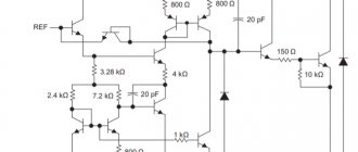
Figure 7 – Block diagram of DS18B20 from the technical description
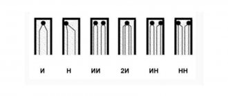
Graphic designation
In UGO thermistor diagrams, the thermistors may differ slightly, but the main sign of thermal resistance is the symbol t next to the rectangle symbolizing the resistor. Without this symbol, it is impossible to determine what the resistance depends on - for example, varistors have similar UGO (resistance is determined by the applied voltage) and other elements.
Sometimes an additional designation is applied to the UGO, which determines the category of the thermistor:
This characteristic is sometimes indicated by arrows:
The letter designation can be different - R, RK, TH, etc.
Comparison of temperature sensor types
The table below shows a comparison of the different types of temperature sensors discussed in this article.
However, keep in mind that this information should be taken as a generalization. The table is intended primarily for those who do not have much experience and/or knowledge about temperature sensors. Table 1. Brief comparison of temperature sensors
| Sensor type | Typical Temperature Range (°C) | Accuracy (+/- °C) | Advantages | Flaws | Application |
| Thermistor |
| 1 |
|
| Ambient temperature measurement |
| Thermocouple | -200° to 1450° | 2 |
|
| Industrial use |
| RTD | -260° to 850° | 1 |
|
| Industrial use |
| Analog chip | -40° to 125° (TMP36) | 2 |
|
|
|
| Digital chip | -55° to 125° (DS18B20) | 0,5 |
|
|
|
Original article:
- Nick Davis. Introduction to Temperature Sensors: Thermistors, Thermocouples, RTDs, and Thermometer ICs
Designations and explanation of markings
There are several types of markings. For example, from letters or different colors, stripes or other images applied to the surface of the thermistor. It all depends on the manufacturer and the specific type of elements. An approximate notation system is shown in the picture below. There are so many options that even an experienced master cannot always decipher them correctly. In this case, it is better to rely on the technical data that is on the thermistor manufacturer’s website in the description of a specific element.
Let's look at an example - an NTC thermistor marked 10 D-9. The first digit “10” indicates that 10 ohms at 25 degrees Celsius constitutes the resistance of the sensor. Its diameter is 9 mm. The higher this value is, the higher the power it dissipates. To better understand color markings, you should use a table or look at the description of characteristics in the reference book. All manufacturers clarify this information for their product lines.
The shape of a semiconductor can be different: thin pipes, large washers, plates of different thicknesses and small elements of different types. There are even parts whose dimensions are measured in several microns. The picture below shows an assortment of semiconductors that are more common than others on the modern market.