Precision measuring instruments are an important component of the activities of all modern sectors of the economy. They serve for timely recording of the consumption of various liquids; they are needed when working with gas mixtures and steam.
In addition to classical flow meters with different operating principles, electronic devices that measure pressure are also often used. Such devices are a mandatory element of most measuring systems and heat meters. They are often part of systems used to implement automatic control.
So-called pressure sensors are in demand at energy sector enterprises, food production, oil refining and other industries where it is necessary to know the digital pressure value to ensure uninterrupted and safe operation of equipment.
What are electronic sensors?
Electronic pressure sensors for water or any other liquid are devices that allow parameters to be measured and processed by special control and display units. A pressure sensor is a device whose output parameters directly depend on the pressure in the location being measured (tank, pipes, etc.). Moreover, they can be used to measure any substance in various states of aggregation - liquid, vapor, gaseous.
The need for such devices is due to the fact that almost the entire industry is built on automatic control systems. A person only performs setup, calibration, maintenance and startup (shutdown). Any system operates automatically. But such devices are also often used in medicine.
Areas of use
Pressure sensors, as devices that convert the measured value into a unified digital signal, can be used in the housing and communal services sector, in production (chemical, food, petrochemical, mechanical engineering, metallurgy, shipbuilding, energy) and for laboratory experiments.
In housing and communal services and in everyday life, such devices are installed in heat metering and automatic control systems for utility networks. Most models are universal and designed for use in liquid, gaseous and chemically aggressive media. Differential pressure sensors are often used in process control systems (filters, pumps, open and closed vessels), and instruments that measure pressure differences are widely used in the energy industry.
Element design features
Any sensors consist of a sensitive element - it is with its help that the effect is transmitted to the converter. The design also includes a circuit for signal processing and a housing. The following types of pressure sensors can be distinguished:
- Piezoelectric.
- Resistive.
- Capacitive.
- Piezoresonant.
- Magnetic (inductive).
- Optoelectronic.
Now let’s look at each type of device in more detail.
How to choose a pressure sensor
First of all, it is necessary to determine what type of pressure needs to be measured (vacuum, relative, absolute, excess). Next, you should select the pressure measurement range, take into account the conditions of use (type and aggressiveness of the working environment), the material of the device body, protection class, determine the need for an analog or digital output signal and temperature compensation (thermometer).
For ease of selection, the catalog of our online store presents general industrial and high-precision sensors in an explosion-proof enclosure with the HART communication standard. From us you can purchase relative, absolute and differential pressure sensors from a proven Russian manufacturer, BD Sensors Rus, at affordable prices.
Resistive elements
These are devices in which the sensitive element changes its resistance under the influence of load. A strain gauge is installed on the sensitive membrane. The membrane bends under pressure, and the strain gauges also begin to move. At the same time, their resistance changes. As a result, the current strength in the converter circuit changes.
When strain gauge elements are stretched, the length increases and the cross-sectional area decreases. The result is an increase in resistance. The reverse process is observed when elements are compressed. Of course, the resistance changes by thousandths of an ohm, so to catch this, you need to install special semiconductor amplifiers.
Piezoelectric sensors
The piezoelectric element is the basis of the device design. When deformation occurs, the piezoelectric element begins to generate a certain signal. The element is installed in the medium whose pressure needs to be measured. During operation, the current in the circuit will be directly proportional to the change in pressure.
Such devices have one feature - they do not allow monitoring pressure if it is constant. Therefore, it is used exclusively in cases where the pressure is constantly changing. At a constant value of the measured value, no electrical pulse will be generated.
Piezoresonance elements
These elements work slightly differently. When voltage is applied, the piezoelectric element is deformed. The higher the stress, the greater the deformation. The basis of the device is a resonator plate made of piezoelectric material. It has electrodes on both sides. As soon as voltage is applied to them, the material begins to vibrate. In this case, the plate bends in one direction or the other. The vibration speed depends on the frequency of the current supplied to the electrodes.
But if an external force acts on the plate, then the vibration frequency of the plate will change. The electronic air pressure sensor used in cars works on this principle. It allows you to estimate the absolute pressure of the air supplied to the vehicle's fuel system.
Output signals
In most cases, industrial pressure sensors use an output signal of 4...20 mA or 0 - 10 V, which are the most common.
In some cases, devices with ratiometric output can be produced.
Such a signal differs in the dependence of its value on the supply voltage. As a rule, this is a signal in the range of 0.5 ... 4.5 V. In fact, “0.5 ... 4.5 V” are such only at a stable voltage of 5 V. If the value of the supply voltage changes, then the output signal will change proportionally.
Electrical connection uses DIN 650 and DIN 43 standards, miniDIN is also available.
It is interesting to connect pressure meters to a PLC (programmable logic controller), which occurs through a closed current loop. The fact is that industrial pressure sensors have only one positive analog output, which is connected to the positive analog input of the PLC, after which the positive power output of the sensor is connected to power.
Current loop
Thus, industrial pressure sensors are powered from their own output signal. This circuit is very economical and convenient, but has a power limit of 20 mA.
Sometimes galvanic isolation is installed in such a circuit, which are modules that separate the power supply for the PLC and the sensor, which helps protect the equipment from power surges.
Capacitive devices
These devices are the most popular because they have a simple design, operate stably and are easy to maintain. The design consists of two electrodes located at a certain distance from each other. It turns out to be a kind of capacitor. One of its plates is a membrane; pressure (measurable) acts on it. As a result, the gap between the plates changes (proportional to the pressure). From your school physics course, you know that the capacitance of a capacitor depends on the surface area of the plates and the distance between them.
When working in a pressure sensor, only the distance between the plates changes - this is quite enough to measure the parameters. Electronic oil pressure sensors are built according to exactly this scheme. The advantages of this type of structure are obvious - they can work in any environment, even aggressive ones. They are not affected by large temperature changes or electromagnetic waves.
Product line "EMIS-BAR"
At the end of 2022, intelligent pressure sensors “EMIS” - BAR appeared in the product line.” They are capable of continuously measuring absolute, excess, differential and hydrostatic pressure, determining the rarefaction of liquid and gaseous media, saturated and superheated steam.
Several design options allow you to make the optimal choice, depending on the tasks and operating conditions, including when working in low-temperature, high-temperature and aggressive environments.
It is worth noting that the customer has the opportunity to choose the materials for the manufacture of the separating membrane and the electronic unit housing, the type, material and size of the flange, the type and material of the bracket. There are also several options for the length of the immersed part of the separation membrane of the plus cavity to choose from. Let us dwell in more detail on the technical characteristics and modifications.
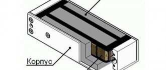
Device structure
- 1. Body;
- 2. Case covers, the front cover most often serves as a display screen;
- 3. RFI and EMI filters – used to suppress electromagnetic and radio interference;
- 4. Electronic unit – processor module;
- 5. Display module – may be missing;
- 6. Pressure receiver – has a different appearance, depending on the type;
- 7. Flanges and hardware – for flanged version;
- 8. Terminal block;
- 9. Setting buttons.
A monocrystalline silicon membrane with piezoresistors located on it is used as a sensor. In this case, the membrane, substrate and resistor are made of the same material - silicon. To protect the sensor, it is available with a separating membrane and filling liquid.
Sensor module device
The sensor module consists of:
- fitting;
- separation membrane;
- sensor;
- cameras;
The signal from the sensor is transmitted via sealed leads to the electronics module.
There is internal software with self-diagnosis capabilities. Basic settings can be configured using the input buttons located on the device. All parameters can also be configured via the HART protocol. In this case, the digital HART signal is superimposed on the analogue one, without affecting its DC component. Menu functions:
- setting the measurement scale with supply of reference pressure;
- damping time setting;
- setting the measurement scale without applying reference pressure;
- setting zero;
- setting a fixed value of the output signal current;
- setting emergency current values;
- blocking control from buttons;
- root extraction function for differential pressure transmitters;
- selection of units of measurement.
“EMIS” - BAR devices are included in the State Register of Measuring Instruments (No. 2219), have a certificate of conformity with TR CU 012/2011 “On the safety of equipment for working in explosive environments”, all the necessary permits, as well as additional certificates:
- Certificate of conformity TR TS 032/2013 “On the safety of equipment operating under excess pressure.”
- Declaration of conformity with TR CU 032/2013 “On the safety of machinery and equipment.”
- Declaration of conformity TR CU 020/2011 “Electromagnetic compatibility of technical equipment”.
- Certificate of Conformity “Use in environments containing hydrogen sulfide.”
- Expert opinion based on the results of sanitary and epidemiological examination.
- The developer's intellectual property rights are protected by RF patent No. 186107.
Available with flange and threaded connections. The customer can choose from several membrane materials, chamber cavity and electronic unit housing, as well as the type of filling fluid.
Find out more
- They have several options:
- with flange connection
- with union connection
- with open membrane
- with remote seal
Find out more
These specifications are available with flange mount and remote seals. Models 186,187, 188 are vacuum converters.
Find out more
Specification 163 – with a flat membrane, 164 – with an immersed membrane. They are used to accurately determine the liquid level in various containers and reservoirs.
Find out more
Inductive sensors
The principle of operation is vaguely similar to the capacitive ones discussed above. A pressure-sensitive conductive membrane is installed at a certain distance from the magnetic circuit in the shape of the letter W (an inductance coil is wound around it).
When voltage is applied to the coil, a magnetic flux is created. It passes both through the core and through the gap, the conductive membrane. The flow is closed, and since the gap has a permeability that is approximately 1000 times less than that of the core, even a tiny change in it leads to proportional fluctuations in inductance values.
Optoelectronic sensors
They simply detect pressure and have high resolution. They have high sensitivity and thermal stability. They work on the basis of the interference of light, using a Fabry-Perot interferometer to measure small movements. Such electronic pressure sensors are extremely rare, but are quite promising.
Main components of the device:
- Optical converter crystal.
- Diaphragm.
- Light-emitting diode.
- Detector (consists of three photodiodes).
Fabi-Perot optical filters, which have a slight difference in thickness, are attached to the two photodiodes. Filters are silicon mirrors with a reflective front surface. They are coated with a layer of silicon oxide, and a thin layer of aluminum is applied to the surface. The optical transducer is very similar to a capacitive pressure sensor.
Materials and tools
To make a pressure sensor circuit with your own hands, you will need to stock up on the following parts and tools:
- Soldering iron of suitable power.
- A fiberglass plate with tracks cut on copper film (their approximate appearance is in the photo on the right).
- Connecting wires.
- Multimeter (necessary for testing the sensor).
In the absence of a ready-made plate with copper tracks (usually purchased through Ali Express), such an element can be made independently. To do this, you should take out a piece of fiberglass and cut it according to the shape indicated in the photo on the right of the workpiece. After this, you need to apply a pattern of spiral droshks on it with varnish, and then etch it in a solution of sodium chloride. The resulting analogue of a proprietary resistive element is quite suitable for the stated purposes. You can also make a pressure sensor from a resistor with your own hands.