Wire marking
Wire marking is the application of a specific mark to their outer surface to indicate the required characteristics. Marking can be in the form of color markings, inscriptions (numbers and letters), labels or tags.
Important! Letter or numerical markings indicate the material of the shell and cores, cross-sectional area, number of cores inside and other parameters.
The red wire indicates the positive phase or plus. You can remember it by the name “Red Cross”. Black corresponds to the negative phase.
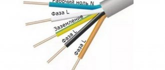
But this designation does not always work: the colors may be different, for example, green and blue, or absent altogether. There are many more colors in three-phase wires:
- The phase is indicated by red, orange, purple or gray colors:
- Neutral - blue or white-blue;
- Grounding - stripes of green or yellow colors.
To avoid mistakes during installation, if in doubt, it is better to check the polarity in advance.
Factory standards
Traditionally, when creating three-phase networks, all cables were colored according to the regulatory documentation of previous years. In wiring that is more than 7 years old, according to the PUE, the following markings were strictly observed:
- yellow, possible greenish longitudinal vein - Phase A
- pronounced green color, sometimes neon tint - Phase B
- red.- Phase C
- bluish or neutral gray tone is allowed - Zero
Common three-phase wiring was designated by the abbreviation Zh-Z-K.
If you are dealing with old wiring from the times of the USSR, then the color of the conductors will only be monochrome: black or white. Electricians recommend not to take risks - when disconnecting, you need to turn on the power and determine the type of strands of the electrical wire using a tester.
Since 2011, GOST RF 50462-2009 began to function on the territory of the Russian Federation. It provides new colors for industrial conductors. The acceptable shades for phases are: A - classic brownish, B - rich black, C - gray, close to metallic. But the contrast of such materials turned out to be inconvenient, and electricians, when installing standard systems, still prefer the old ZH-Z-K range to the K-H-S formula. Bright veins are better visible in any lighting, the contrast of the design gives a quick understanding of the situation.
The letter designation makes it easier to recognize the nuances of the circuits: A is L or L1, B is L2 only. C is L3 and zero is N. Therefore, a knowledgeable craftsman will immediately understand what color the phase wire is when composing the circuit.
According to generally accepted standards, when creating AC or DC electrical circuits using protected conductors, all of the above shades are acceptable.
The complete set of the European socket implies the presence of three components: a bright phase one (it can be red, purple, brown or another rich tone), a blue-blue shade that is safe for humans, and protection in a yellow or green color. Wire markings are recognized only as generally accepted.
Wire color coding
Checking the polarity of the wires
It happens that the wiring has different colors or combinations, or is even completely enclosed in a white shell without any signs. In this case, it is necessary to determine the polarity using tools.
Important! After determining the polarity, it is worth marking the wires so as not to mix them up in the future. The mark can be made with colored tape, permanent marker or heat shrink tubing.
To help determine the correct polarity:
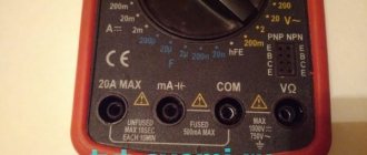
- Multimeter: This is the simplest option. On the device, you need to set the DC current measurement mode to 20 V, then connect the black probe (minus) to the “COM” socket, the red (plus) probe to the “VΩmA” socket. Then the probes are connected to the wires. If the numbers appear on the screen, it means that the probes are connected correctly - black to minus, red to plus. If a minus sign (“-”) appears in front of the numbers, it means that the probes are connected incorrectly: black to positive, red to negative.
Important! When using a multimeter with an arrow, if connected correctly, the value will be correct; if connected incorrectly, the arrow will deflect in the opposite direction.
- Indicator screwdriver: when you touch the phase wire, the circuit closes and the control lamp lights up. This is an inexpensive and reliable tool, quite durable and does not require additional resources. The disadvantages include low accuracy and the possibility of false positives.
- Lamp: you need to screw an incandescent lamp into a standard socket, connect the wire to a known zero line and check the others one by one, connecting them. A lit lamp will indicate the presence of a phase.
- Battery: the wires being tested need to be connected at one end to different sides of the battery (to “+” and “-”), and with the other end to touch the speaker terminals for a couple of seconds. If the diffuser moves outward, the wire is connected correctly, if it “retracts” inward, it is incorrect.
- Raw potatoes: cut them in half and stick two wires with their bare ends at a distance of 1-2 cm from each other. The other ends are connected to a DC source, the device is turned on and left for 15-20 minutes. A green spot will form near the positive one, bubbles will appear near the negative one - hydrogen will be released.
- Warm water: one end of the wires is connected to a power source, the other is immersed in warm water. After turning on the device, bubbles will begin to collect near the negative wire.
Checking the correct connection using a multimeter
If the home master is not sure about the correct connection of the cores in the DC network, then the markings can be easily checked using a multimeter.
- Set the device switch to the appropriate position for measuring DC voltage.
- Connect the probes to it (black ̶ into the “com” socket, and red ̶ into the “V” socket).
- Touch the probes to the wires, observing the color markings.
Now you need to look at the multimeter display. If a minus sign appears in front of the displayed value, it means that the wire connections are incorrect. The absence of a minus sign indicates a correct connection.
PHOTO: YouTube.com Such readings indicate that the source is connected incorrectly - the polarity should be changed
Security measures
When working with electric current, the following precautions must be taken:
- Use devices only for their intended purpose;
- Do not turn on equipment with damaged wires and plugs, do not use faulty sockets;
- Do not touch wires or outlets with wet hands or while standing on a wet floor. When working in a room with high humidity, you need to use rubber gloves and a mat;
- Do not bend wires and cables;
- Before starting work, it is worth disconnecting the entire network;
- If the equipment sparks or starts to catch fire when turned on, do not touch it. It is necessary to turn off the power through the panel;
- If you have any doubts or fears, it is better to contact a specialist or choose a safer option, for example, determining the polarity using a potato rather than connecting to a device.
Wire Classification Options
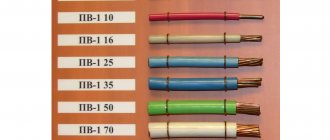
The typical cable name contains letters and numbers. By decoding these symbols you can find out the main characteristics of products in this category:
- conductor (shell) materials;
- number of cores;
- cross-sectional area;
- Extra options.
Example of decoding (AVBbv-ng):
- A – the core is made of aluminum (copper is not marked);
- B – insulating shells are made of PVC;
- BB – protection against mechanical damage, made of steel tape without a damping gasket;
- ng – components that prevent combustion have been added to the polymer shell.
General concepts about the device
Car receivers are divided into two types depending on the method of their installation:
- Stationary - suitable for certain car brands due to their original shape and non-standard size. Such models are built into the car at the assembly stage. For example, such a model is the standard radio on the Chevrolet Cruze DWGM1001 or the Subaru Clarion model installed on the Subaru Impreza.
- Built-in - universal receivers, most have a removable front panel to protect against theft. An example of such models are Pioneer players.
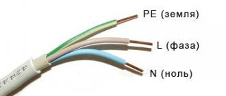
Marking of wires for alternating three-phase current
The special color designation of the shell helps to determine the purpose of individual lines even without studying the accompanying design documentation:
- gray, purple, orange or red wire – phase;
- yellow and green stripes – grounding;
- blue or a combination of white and blue stripes is neutral.
Such designations simplify installation operations when laying power lines during the assembly of electrical panels. It is especially important to eliminate errors when hidden installation of communications inside building structures is used. In this case, correcting incorrect actions will be accompanied by increased costs.
Coloring phase
In cases where the electrical installation is installed using rigid metal busbars, the tires are painted with indelible paint in the following colors:
- yellow – phase A (L1);
- green – phase B(L2);
- red – phase C (L3);
- blue – zero bus;
- longitudinal or inclined stripes of yellow and green color – grounding bus.
The color of the phases must be maintained throughout the entire device, but not necessarily over the entire surface of the bus. It is allowed to mark the phase designation only at the connection points. On a painted surface, you can duplicate the color with the “ZhZK” symbols for paint of the corresponding colors.
If tires are not accessible for inspection or work when there is voltage on them, then they may not be painted.
The color of phase wires connected to rigid busbars may not coincide with them in color, since there is a difference in the accepted designation systems for flexible conductors and rigid stationary distribution busbars.
Color of wires plus (+) and minus (-) in DC networks
Is the red wire positive or negative? Such questions arise when working with DC electrical circuits.
Red
To remember which plus is red or black, they use the name of a well-known international organization - the Red Cross. This phrase suggests that red means plus.
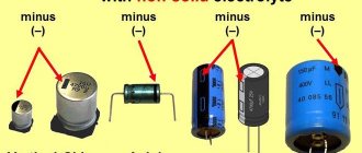
Black
Black color indicates the negative conductor. These markings can be seen on typical household equipment:
- power supplies;
- audio, video equipment;
- other devices with electronic software control units.
Plus
The polarity of conductors must be observed when repairing standard electrical equipment of cars. In some situations, confusion with plus and minus is accompanied by a violation of the functional state.
Minus
The high power of connected consumers increases the responsibility for performing repair and adjustment work. In such situations, it is necessary to eliminate errors in determining polarity. Strong direct current is used to supply electricity:
- warehouse and municipal transport;
- lifting mechanisms;
- sensors and automation.
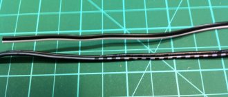
black wire with white stripe
In the Technology , to the question 2 wires come out of the power supply. Both are black, one has a white stripe. Which one is “+”? asked by the author Taksakos the best answer is with a white stripe+
, then: you need to use an indicator screwdriver; on which wire the light bulb in the screwdriver lights up, this is the phase - “+”, on which there is no - ground, “-“. If -constant-, then: connect a digital multimeter (voltmeter) to both wires, and if it does not show the “-” (minus) symbol, then it means a direct connection, and it’s not difficult to guess which is minus and which is plus (wire, to which the red wire of the multimeter is connected - “+”) PS. In general, black usually means zero (minus), and the other (usually red) means plus, but who are these Chinese if the power supply is Chinese?