Soldering bga chips
How to solder boards? And how does BGA stand for? Bgacenter experts answer these two frequently asked questions during soldering courses. From English - ball grid arrey, that is, an array of balls that looks like a grid. Solder balls are applied to the microcircuit through a stencil, then a stream of hot air melts the solder itself and contacts of the correct shape are formed.
And the soldering process consists of a certain sequence of actions, following which we obtain a high-quality connection. But there are a large number of nuances for which people come to study.
Starting with at what angle and at what distance from the board to hold the hair dryer nozzle, temperature conditions for dismantling and installing microcircuits, from which side to start the paddle. And during diagnostics, and there is an interlayer short circuit, nothing heats up.
How to find the faulty element or circuit in this case? And many other subtleties that a current service center master can know. And the one who can confirm his level with completed repairs.
iPhone repair at Bgacenter
Reballing procedure
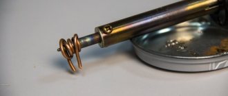
To carry out reballing, the chip is placed in a stencil and secured with specialized electrical tape. Apply solder paste on the back side with a finger or spatula, then set the hair dryer to a temperature of about 300 degrees and begin to warm it up. After the characteristic shine from the molten solder paste appears, allow the solder to cool completely.
To free the stencil from the chip, remove the electrical tape and heat the stencil to approximately 150 degrees; at the end of the procedure, the part should be free. It happens that it is impossible to immediately remove a part from a Chinese stencil, so it may be necessary to carefully hook it.
During reverse soldering of the microcircuits, the risks are assessed and the chip is laid out the required number of times to ensure an exact match of the heels and balls. Then they set the temperature on a soldering hair dryer to 330 to 350 degrees and heat until the melted solder allows the chip to fall into place on its own.
Source
Soldering the chip
90% of the success of the repair depends on the correct dismantling of the microcircuits. It is at this stage that it is important not to tear off the nickels and not damage the microcircuit with high temperature. And they begin desoldering the chip by removing the compound.
Compound
Compound is a polymer resin, usually black or brown, used in the manufacture of telephone motherboards. Purpose of the compound:
- Additional fixation of radio components and bga chips on the board.
- Protection of non-insulated contacts from moisture.
- Increased board strength.
The most critical microcircuits, such as: CPU, BB_RF, EPROM, NAND Flash, Wi-Fi, are filled with compound at the factory after installation. And before dismantling, it is necessary to clear the perimeter of resin.
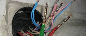
Removing the compound
Dismantling sequence
- Carefully inspect the board for previously performed repairs.
- Perform diagnostics and take the necessary measurements.
- Prepare the board for soldering, remove protective screens and stickers. Disconnect and remove the coaxial cable.
- Secure the motherboard in the appropriate holder.
- Remove the compound around the chip being removed. The temperature on the hairdryer is 210 – 240 degrees Celsius.
- Install heat sinks. The installation location of the heat sinks depends on the location of the soldered chip.
- Use a hairdryer to warm up the board for a few seconds. Thus, we increase the temperature of the board so that the flux spreads evenly.
- Apply FluxPlus, or any other no-clean flux, to the surface of the chip.
- Direct a stream of hot air onto the element to be soldered. Temperature during dismantling is 340 degrees Celsius. How can you tell when the solder has melted and it’s time to remove the chip from the board? There are several ways to do this:
- Track time using a stopwatch.
- Count down the seconds to yourself.
- “Push” with a probe or tweezers the microcircuit itself or the nearby harness (capacitors, resistors or coils). As soon as the chip being soldered begins to move, by a fraction of a millimeter, it is time to place the spatula under or use tweezers.
- Prepare the contact area. For this:
- Use a special spatula to remove any remaining compound;
- tin all contacts without exception with Rose alloy;
- use braid to collect solder residues from the working surface;
- After the motherboard has cooled to room temperature, wash the contact pad with alcohol, BR-2 or DEAGREASER.
- The board is prepared for installation of a working microcircuit.
Soldering chips
How to desolder a radio element
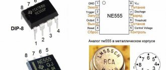
Soldering DIP chips
- Sequence of actions for desoldering:
- Remove varnish from the chip solder areas with a brush or cotton swab dipped in acetone or remover (in the case of a varnished board).
- Remove any remaining solvent and varnish with a brush dipped in ethyl alcohol.
- Heat the soldering iron to operating temperature.
- Touch the soldering iron tip to the first leg of the chip (on the back of the board) until the solder completely melts.
- Remove melted solder with a suction syringe. When using a needle instead of a syringe, place the needle on the leg of the chip and, turning the needle around its axis, lower it all the way into the hole.
- After completely removing the solder from the hole, start desoldering the leads from the next hole.
- Remove the microcircuit after all pins have been completely unsoldered.
On video: How to properly desolder a DIP chip
Dismantling planar chips
The sequence of actions for desoldering SOIC - chips that are not glued to the board:
- Remove varnish (if any) from the legs of the microcircuit with acetone or remover. After removing the varnish, clean the board from any remaining varnish with ethyl alcohol.
- Apply liquid flux to the soldered leads on all sides of the chip.
- Solder (short circuit) all the legs of the chip on each side, passing the tip along all the pins of the chip and dispersing the solder along the legs. There should be a lot of solder applied to the legs so that after removing the soldering iron, the solder continues to be in a molten state.
- Run the soldering iron over all sealed sides of the chip, ensuring the solder melts on all sides, then remove the chip with tweezers.
- To unsolder a microcircuit glued to the board, you need to unsolder each pin of the microcircuit one by one, lifting it with tweezers above the contact pad. After unsoldering all the legs, remove the microcircuit mechanically (with a knife), being careful not to damage the board.
On video: How to dismantle a planar microcircuit
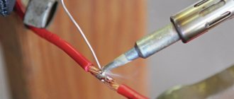
Soldering microcircuits with pins
Soldering should be done in the following order: 1. Install the chip into the holes on the board. 2. Apply flux to the pins of the microcircuit on the back side of the board. 3. Solder each pin of the chip into a hole on the back of the board. 4. Remove any remaining flux.
Installation of SOIC chips
It is convenient to solder SOIC chips using a “wave of solder”. The method is based on the capillary effect, under the influence of which liquid solder flows between the lead and the metallized area, wetting them and forming a drop.
Soldering microcircuits with a “wave solder” using a soldering iron is carried out in the following sequence:
1. Tin the contact pads and apply flux to them. 2. Install the chip on the board, align the legs with the board pads and solder one corner pin (any). 3. Solder the second corner pin to the metallized pad, located diagonally on the chip opposite the first soldered leg. At the same time, make sure that the remaining pins of the microcircuit are aligned with their metallized pads. 4. Apply flux to all pins of the chip. 5. Pass the tip over the pins on each side of the chip several times to disperse the solder across the pins. 6. If solder bridges have formed between adjacent terminals, remove the excess using metal braid. It should be placed on top of the jumper and heated with a soldering iron tip. Excess solder will be absorbed into the braid. Then run the soldering iron tip across the leads again.
Soldering bga chips
The general principle of soldering is as follows: thanks to the surface tension created when the solder melts, the microcircuit is fixed relative to the contact pad on the system board. Soldering temperature for bga chips on iPhone boards is 320 – 350 degrees Celsius.
Preparing the chip:
- Use a special knife to clean the compound.
- Use a 1 or 2 mm copper braid (depending on the geometric dimensions of the chip) to remove any remaining solder.
- Restore the ball leads. There are two ways to draw conclusions:
- BGA paste is applied through a stencil to the surface of the microcircuit (priority method) Used in most cases.
- Manually, with BGA balls. This option is suitable for chips with a small number of pins, up to 50. Although a few years ago, when the quality of stencils left much to be desired), modems on the iPhone 5S were rolled manually. That is, each ball was installed separately using a probe or tweezers. And this is 383 contacts, as calculated by ZXW. If, when distributing balls on a chip glued to a stencil, the balls are not fixed in the holes of the stencil; this means that not enough flux has been applied to the microcircuit.
- If we are working with paste, be sure to warm up the microcircuit with a hairdryer after removing the stencil to form contacts of the correct shape. Additionally, fine-grained sandpaper, P500 GOST R 52381-2005, can be used for these purposes.
- Use alcohol and a toothbrush to finally clean the microcircuit.
- Solder the chip onto the contact pad, installing it along the key and gaps.
- When installing a new microcircuit (purchased from a supplier), a mandatory procedure is to roll the chip onto lead containing solder. This is necessary to lower the melting temperature of the solder and reduce the time the board is exposed to high temperatures.
Soldering bga/BGA soldering
Soldering iron for microcircuits - how to choose the right one
All electric soldering irons that can be found in a store or on the Internet differ in their characteristics. To answer the question of how to choose a soldering iron for soldering microcircuits, you need to determine its main parameters:
- · Power. For micro-soldering of microcircuit pins, it is enough to choose a soldering iron with a power of 20 to 35 W. More powerful soldering irons may cause components to overheat.
- · Dimensions and weight. The best thing is a small soldering iron that fits comfortably in your hand. The soldering iron is always held in the fingers, like a ballpoint pen, so it should be miniature and light. You should not buy massive soldering irons with wooden handles - they cannot be properly grasped in your hand. It is not recommended to purchase pistol-shaped soldering irons - they are difficult to solder parts on printed circuit boards.
- · Design. When choosing, you need to pay attention to the material of the handle (it should be comfortable, non-slip, and not rub calluses), the design of the electrical cord (the cable must be double insulated, with a wire cross-section of at least 2.5 mm, elastic so that it does not interfere when working).
- · Availability of a temperature controller (thermostat). To ensure high-quality soldering, the temperature of the soldering iron tip should be from 260 to 300 °C, not higher. If there is no built-in controller, it is better to choose a soldering iron with a power supply of 12 V or 36 V. According to reviews from radio amateurs, Taiwanese 220 V soldering irons are the worst at controlling temperature - they overheat, which is why it is not possible to solder the microcircuit properly. As a way out, the soldering iron is turned on through a power regulator, which you can purchase or make yourself.
- · Shape and type of sting. The best choice is a soldering iron with interchangeable tips. For soldering planar microcircuits, a tip with a diameter of 2 mm with a cut of 45° is best suited, which is convenient for soldering legs with “wave solder”. Thin conical nozzles are convenient for soldering microcircuits with pin terminals in metallized holes on the board. Soldering tips must have a special coating that prevents the appearance of carbon deposits. You should not use ordinary copper attachments - they quickly burn, oxidize, and need to be cleaned periodically.
- · Availability of a soldering station. A soldering station is a separate unit with a controller and temperature regulator, to which a soldering iron and other elements (hair dryer, thermal tweezers) are connected via a connector. The station is used mainly for professional or permanent soldering work; for one-time repairs at home, its cost is too high (from 3 thousand rubles).
On video: How to choose a soldering iron, advantages and disadvantages of certain models.
Bottom heating for bga soldering
To reduce the time the board is exposed to high temperatures, the boards are heated. We recommend the monoblock PCB heater STM 10-6. Stable maintenance of the set temperature over the entire area of the heating element contributes to uniform heating of the entire motherboard (depending on the heater model). And one more advantage over other thermal tables is a convenient universal fastening system.
Thermal table STM 10-6
Flux for soldering bga
There are a huge number of flux manufacturers on the market. Bgacenter uses the widely used FluxPlus. You should pay attention to the date of manufacture and expiration date of the flux. Advantages of flux gel:
- no-wash (many professionals recommend washing anyway);
- convenient dispenser, hence high dosing accuracy during soldering work;
- does not emit unpleasant odors;
- ensures good spreading of solder over the base metal, thereby reducing the surface tension of the molten solder.
FluxPlus
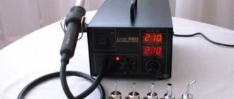
Hot air soldering station
The purpose of the Quick 861DE ESD Lead station is soldering (disassembly and installation) of BGA microcircuits and SMD components. Advantages of this station:
- three memory modes CH1, CH2, CH3;
- high air-to-air performance, Quick 861DE is suitable for soldering circuit boards, phones and laptops;
- temperature stability.
What could be improved in the design of the station is temperature control not with buttons, but with rotary controls, as on the Quick 857D (W)+.
Quick 861DE ESD Lead
Soldering iron
PS-900 METCAL – induction soldering system. A soldering iron power of 60 W is quite enough to work with multilayer boards of modern electronics. Phone repair engineers have 4 years of experience working with this particular soldering iron. What are the distinctive features of the PS-900:
- no need for calibration,
- large selection of tips,
- reliability of the station, the consumable material is the inductor. With daily intensive soldering, the inductor is replaced on average once every 10 months.
Soldering iron
Binocular microscope
For a novice phone repairman, the CM0745 microscope is a good option. Binocular microscope with a focal length of 145 mm (with a Barlow diverging lens installed). The purpose of the lens system is to increase the focal length while maintaining the working area.
Advantage of CM0745:
- Smooth increase is achieved using a ratchet.
- The lens system is made of glass, not plastic.
- Possibility to equip the microscope head with different tables and stands.
- Magnification up to 45X.
Microscope for soldering circuit boards
Minimum set of tools for work
Before starting to connect complex elements, a novice DIYer should become familiar with the basics of conventional soldering. As a rule, it is done using a simple electric soldering iron with a copper tip, called a tip.
In addition, for any soldering a minimum set of materials is required:
Tools and materials for soldering.
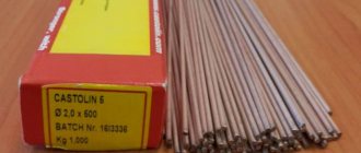
- Solder. An alloy of tin and lead, characterized by high fusible properties and used for attaching elements to the motherboard or each other. In the recent past, pure tin was used for solder, but today such material is unreasonably expensive. In addition, the strength characteristics of the lead-tin alloy are in no way inferior to pure metal. In specialized shopping centers you can purchase different types of solder that have standard or improved properties.
- Flux. The use of fluxes facilitates the soldering process and prevents oxidation of the metal of the soldered elements. Today, the most popular material used as a flux is purified wood resin - rosin. In stores you can find special compounds designed for soldering specific metals. Thus, when soldering nickel, stainless steels and aluminum, a substance made from rosin and acid can be used.
You can start working only when all soldering tools have been assembled.