Preparatory work
Before you start making an extension cord, you should decide in what conditions it will be used.
Don’t forget the power of connected devices. After all, it depends on this which cable you should buy to make an extension cord.
Once you have decided on the desired requirements, you should prepare a list in which you indicate which components you need to assemble a high-quality extension cord.
Tools and materials needed for work
First you need to decide on the cross-section of the wire used as the cord. We recommend using copper wire.
If the extension cord will be connected to a grounded outlet, we recommend purchasing a three-core wire.
It is also worth deciding on the wire cross-section. A wire with a cross-section of 1.5 mm can withstand a load of up to 3.5 kilowatts.
If you plan to connect devices with a larger capacity, then it is advisable to use a wire with a cross-section of 2.5 mm. This wire can withstand loads of up to 5 kilowatts.
To make an extension cord that uses high power, we recommend finding tables on specialized forums or websites of cable manufacturers. They indicate the wire cross-section and the power for which they are designed.
You should carefully consider the choice of plug. If your sockets are of an old design, you should not purchase a Euro plug.
Try to decide on the number of outlets that will be required for the extension cord. It is not advisable to use a single outlet.
Of course, if necessary, you can connect a home-made extension cord with a factory-made version that has several outlets. But it is advisable to provide two or three sockets in the manufactured version.
When purchasing a block with sockets, try not to confuse it with the option that is used when working with open wiring. The back part of such pads very often falls out; there are no clamps to protect against the forks accidentally falling out of the socket.
What switches are used?
A single-pole product is used to de-energize a group of lamps, and is installed in any small room with one group of lamps.
A double switch is a product that allows you to perform closing and breaking actions with two groups of lighting fixtures. Let's say two types of lighting are designed in one of the rooms: main and spotlights. In this case, control must be carried out separately. One key regulates the lighting of the main line, and the second – additional. In addition, there are options with two different luminous flux powers.
A three-key switch can control three groups of lamps. Typically, this option is suitable for installation in a corridor, when it is necessary to control lighting from one place in three rooms at once (kitchen, bathroom and toilet).
Properly connected cables are so important that it could not be more important, since the issue concerns electrical safety. Ask about this to people who have inadvertently touched this dangerous place. It's like being born again. It’s good when you can get away with shock and avoid a short circuit.
Before starting installation, you should prepare the tool and think about what technology to use. As an example, we can offer step-by-step instructions.
Multicolored switches
My mother-in-law's extension cord broke. Extension cord with switch. This switch did not work. Brought it to me for repairs. Is it possible to refuse almost a relative?! I'll try to be brief. The extension cord is the most common cheap Chinese one.
Switch for two lines. One contact simply melted away. I took it out (contact) and soldered the wire directly. The other contact was not affected. The switch now turned off only one line, but everything worked.
I added a 5A fuse, the protection will not hurt. This extension cord works for the TV, no other loads are provided.
Parallel to both lines there is a protective varistor 10D471K against overvoltage (interpretation - diameter 10mm, voltage 470 Volts).
But the protective principle of the varistor does not fit into the form factor of the extension cord. There was a missing safety switch. I installed a fuse for this reason too. I assembled the extension cord and everything works. But doubts still tormented me. I didn't give it away. I decided to install a full-fledged switch. I live on the outskirts of the city. There are no radio stores nearby. I didn’t want to go to the center because of a trinket. Moreover, all this was not in a hurry. I checked Aliexpress and ordered it there. I still don’t know the real cost of these switches (offline). I ordered 4 pieces at once, all in different colors. Why do I need 4 pieces, I don’t know myself. Probably, in childhood there were not enough such toys. I haven’t played enough :) The seller gave a full track, but the parcel took a long time (more than six weeks).
It was packaged super. Several layers of bubble wrap, held together with tape.
Inside is a standard bag with a lock.
Exactly 4 pieces. Exactly the colors I ordered.
For those who are at least a little familiar with a soldering iron and have straight hands, they will definitely do. The dimensions are exactly the same as those given on the seller's page.
There are also no discrepancies with the one being replaced. He stood up like a native.
Soldered without problems. The solder contacts are tinned well.
I didn’t remove the fuse, that’s not why I installed it. I thought for a long time about what color to put it in. I settled on the usual red. Turned it on, everything works.
I compared the replaced one with the purchased one.
Both are 16A. And at the same time, I don’t recommend using either the one or the new one on 16A. This is clear upon analysis. I've never taken them apart. That's why it was interesting. Conventional molded plates are used as contactors.
The principle of operation of the backlight was clear from the beginning, but I also didn’t know how they implemented it.
The new ones are designed a little differently.
Contactors are a little more reliable.
But I’ll repeat it again. I wouldn't risk using them on 16A. That's basically all. Overall, I'm happy with the purchase. Always useful. Surely there will be those who find it cheaper to buy a new extension cord to replace a broken one, especially since not everyone can do it (or maybe they won’t want to). And I'm always more interested in fixing things. That's it. Good luck!
Installation features
block
It will not be difficult to install a combined unit without the involvement of a professional electrician, since connecting modern models requires a minimum of wires.
The installation process will have only a few features that need to be taken into account:
- You need to prepare the necessary tools in advance ; you won’t need many of them: an electric drill with a drill core; several screwdrivers of different sizes; pliers and wire cutters.
- To ensure safety during work , make sure that the handles of all tools are insulated.
- Some modern varieties are designed for external installation, that is, when installing them, you can completely avoid drilling holes in the wall surface.
- You can choose a variety with an increased level of protection from environmental conditions ; such models can be installed not only indoors, but also outdoors. Such devices also have an additional element in the design in the form of a special lid that helps prevent liquid from getting inside the device.
- All modern types of blocks are suitable for installation in walls made of any material and regardless of the type of finish.
The most common installation mistakes
During installation of the socket block, the following errors may be made that can affect the visual appeal or performance of the product:
- Use for connecting to an aluminum wire by twisting the conductor with a copper core. Such an error can lead to contact failure due to oxidation and failure of the product. The cores of the connected current-carrying wires must be either made of the same metal or connected through a terminal block
- Using a flat wire with a single layer of insulation and embedding it in the wall without placing it in plastic or corrugated tubing. This method was previously permitted, but the use of additional containment is now recommended.
- Application for the manufacture of jumpers of wires of different sections. This cannot be called a gross mistake, but for these purposes it is recommended to use a core with a cross-sectional area equal to the cross-section of the electrical wiring
- Connecting the RE conductor in a daisy chain method, that is, using jumpers between the sockets. As mentioned above, this method is considered a violation of the PUE
- Leaving too long ends of the wire when entering a socket box or junction box. For comfortable work, the ends of the wire should be 12-15cm. Otherwise, problems may arise with its installation when installation is completed.
- Installation of splices or twists of wire in a cable channel or groove. All contacts and connections must be made only in electrical installation boxes (distribution or socket boxes). This facilitates the repair and inspection of electrical networks.
By avoiding the listed errors, the user will be able to independently mount the socket block and use it for a long time.
How to connect an extension cord to the network using a lamp
So, we will need pliers, insulating tape, a lamp, wire cutters and the extension cord itself. Take the lamp, carefully break the glass, and use pliers to remove the glass burrs from the threaded part of the lamp. We leave the central glass rod, then we bite off the central antennae with pliers, leaving the side electrodes.
We take an extension cord plug, one electrode and tightly wrap several turns onto the pin of the plug and insulate it with insulating tape. Moreover, the glass rod should be between the pins of the plug in the middle.
We do the same with the second electrode and part of the plug, then we wrap the entire connection with tape for elasticity and insulation. We screw our assembly into the socket, turn on the switch and the extension cord under voltage.
Preparatory work
When working with electrical equipment, extreme precision and caution must be observed, therefore all materials and tools needed for the work must be prepared and purchased in advance:
- flat and Phillips screwdriver;
- pliers;
- side cutters;
- insulating tape;
- a good construction knife with a sharp blade (for stripping wire ends);
- for crimping it is more convenient to use a special tool - a crimper (it is not necessary if the wires are not stranded);
- switch;
- wires.
Switch Wiring Tools
It is very important to turn off the power supply before starting work!
It is extremely important to draw the connection diagram and lay out the wiring correctly in advance.
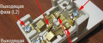
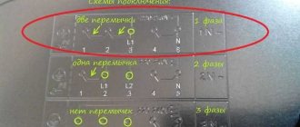
Connection diagram for a two-key switch
The circuit should include the following three wires:
- Ground wire (exited to the light source, indicated on the diagram as “0” or with an arrow pointing down).
- Neutral wire (also led to the light source, designated by the letter “N”).
- Phase is a live wire that, when turned on, should provide power to the light bulbs (the terminals for the phase wire are designated by the Latin letter “L”).
Wire connection sequence
You can install the wiring in one of two possible ways: open or closed. For the first, you will need additional materials - corrugated pipes or grooves, for the second - you need to cut grooves in the walls.
Please note that wiring installation is done before plastering the walls and ceiling.
To install the socket box under the switch, you will have to hollow out a recess in the wall; you can use a chisel and a hammer, but it is better to use a hammer drill with a special crown.
Read how to connect a pass-through switch here.
Now let's look at a real example of assembling a carrier.
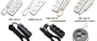
Let’s say you need to make a carrying case, which will include a heater with a power of 1.5 kW, sometimes a drill with a power of 0.85 kW will be turned on, or some other small thing: a phone charger, a portable lamp, a soldering iron, and maybe something else. If you calculate the total power of all these devices, it will be no more than 3 kW. Based on this, I will take PVS wire 3 * 1.5 mm 2, it will be enough. There will even be a power reserve.
I’ll make a small digression and explain a little what these numbers mean - 3 * 1.5 mm 2.
3 – the first digit always indicates the number of cores in the wire. It is advisable to take a three-core wire for carrying, since in addition to phase and zero, we will also have grounding.
1.5 mm 2 is the cross-section of one core. It happens that in a wire or cable several cores have one cross-section, and one or more wires have a different cross-section.
Let's return to our assembly. In the store we buy a socket or block of sockets with a grounding contact. If our load is 3 kW, then the current will be approximately 13.6 A. Therefore, we buy sockets that can withstand 16 A. We also take a plug for 16 A, and it is imperative that it has a grounding contact.
Let's start assembling the carrier.
We have all the necessary materials and tools. First you need to disassemble the fork. Most plugs have a screw type connection. If you take and simply clamp a stripped stranded core with a screw, a significant part of the wires will be damaged.
As a result, the area of the contact connection may decrease, which can subsequently lead to heating and various breakdowns. Starting from the banal burnout of the wire, and ending with the complete failure of the plug.
Therefore, we will use special tips for crimping NShVI.
First you need to strip the wire. Carefully remove the top insulation, and then strip the wires to the length required for crimping with lugs. For stripping, it is best to use a special knife.
But if you don’t have one, then you can use any knife. By the way, I would not recommend stripping the wires with a stationery knife, as it cuts the wires. But it is very suitable for removing top insulation.
Now we crimp the wires, and you can start assembling the plug. Typically, all plugs are equipped with a special clamp to secure the wire. We clamp the outer insulation of the wire with a clamp and connect the wires to the contacts of the plug.
Attention. I want to explain to you why it is necessary to secure the wire with a clamp. The fact is that many people, when turning off a carrier or other electrical appliances, pull not by the plug, but by the cable. And thus the contact connection of the core with the plug contact may be damaged. Or the wire may even pull out.
Now we connect the wire to a socket or socket block. To do this, let's disassemble it. The grounding wire, in the same way as in the case of the plug, is pressed into the NKI tip. If this is not the case, then simply twist the core into a ring and connect it to the grounding contact. We connect the remaining two wires to the corresponding terminals.
Now, to close the cover of the socket block, we need to make a special recess for the wire. Carefully cut it out, then lay the wire, close the lid and screw it on.
To make everything clearer, watch the video.
And in this video, a person makes a carry without explanation.
In principle, everything, the carrier is ready and can be used. But you and I can improve it and insert a button into it.
How to connect a single-key switch from an outlet
Often, in solving practical problems when connecting additional lamps or just light bulbs, the need arises to connect a switch from the outlet. You can do this in two ways:
- By connecting the phase from the socket and the neutral to the ground from the distribution box, when the lamp is close to the latter.
- Connecting phase, neutral and ground from the socket when the light bulb is far from the source and pulling wires across the entire apartment is impractical.
Interesting! Ultimately, it is up to the owner to decide which option to choose. However, it should be taken into account that if the outlet is constantly loaded with powerful devices, then its contacts can quickly weaken. Over time, this will lead to deterioration of the lighting device's power supply. The mechanism of sequential actions for connection for both versions is no different (except for the connected power) from when the socket outlet is already connected and in operation, and is given below.
Preparing for work
- Fulfill the basic electrical safety requirement before carrying out work, that is, turn off the power supply line.
- Understand cable markings. The color scheme will make it clear which core is phase and which is zero. A phase conductor is connected to the electrical installation product, not a neutral one. In electricity, you don't learn from mistakes. Here, only experience and knowledge matter.
- To connect the wires, the soldering method, screw clamp, or, in extreme cases, twisting is used.
Soldering takes quite a lot of time, but in this way one of the strongest connections is achieved. The cooled cores are insulated in a simple way.
The main advantages of the screw clamp include the lack of need for insulating the connection. This method allows you to connect cables made of aluminum and copper.
The simplest and most common is considered to be ordinary twisting. The disadvantage is the gradual weakening of the connection. But a normally performed twisting often lasts for many years without causing disturbance to residents. The main thing is to do it efficiently.
As for tools, there should be a special set available that will come in handy more than once in your work. In your jacket pocket or electrician's handbag you always have the necessary screwdrivers, a voltage indicator, pliers with insulated handles and a stripper. It is best to remove the insulation from the wires last. Over time, you will decide for yourself which tool is convenient and preferable for you.
How to assemble an extension cord on a reel
A semi-professional extension cord should provide current transmission with a power of 32 A per 50 m. For example, power a bathhouse in the country. The total power of the devices will be 7 kW! In this case, you will need a three-core stranded cable 3x10 mm. 50 meters of such cable weighs about 20 kg.
Only using a coil will it be clear how to make an electric carrier weighing more than 20 kg.
Where to get a reel
There are two options:
- Make/order a welded frame, cut out two circles from thick plywood, buy studs, bolts and nuts, assemble such a structure.
The cost of the product will be 1.5-2 thousand rubles. - Buy a reel without cable for 300-500 rubles.
But you will additionally need a set of electrical installation products with IP44 protection, rated for 32 A.
Key stages in the manufacture and assembly of an extension cord coil
Making a bushing for a drum. A universal homemade extension cord reel will rotate
Therefore, it is important to make a reliable bushing with locking washers. To do this, you need to take a pipe with a cross section of 20 and 25 mm
The material is cut to the width of the drum, taking into account the installation of the fixing bolt. In this case, a tubular element with a cross-section of 20 mm must be cut with a margin of at least 5 mm in width. The smaller pipe diameter should fit freely inside. On the sides of the axle, bushings machined from steel 2-4 mm thick are installed. The moving element is fixed with an M8 or M10 bolt. Reel stand made of profiled pipe. In the instructions in the photo, which shows how to make a reel for an extension cord, there is a structurally important element - a U-shaped stand. This part can be made from sections of profiled pipe 20x20 mm and 20x40 mm. Initially, it is important to determine the dimensions of the structure taking into account the dimensions of the rotating drum. A 20x20 mm pipe is cut to the required parameters and welded together in the shape of the letter P. The central part is marked in the center. After which a 20x40 mm pipe is welded vertically.
- Attaching the drum axle to the stand. The axle must be welded to a 20x40 mm pipe. It is first necessary to note the height position of the drum. A 20 mm round pipe is welded to the profiled electrode welding. You will also need a thrust washer, which will act as a retainer for the drum. If necessary, the washer can be welded to the profile.
- Handles for reel and supporting frame. Handles are necessary for ease of use of the reel. Handles from a grinder or drill are suitable as the main elements. The large handle must be secured to the upper part of the 20x40 mm profile using a nut. The small one should be located on the coil itself. The handle for rotating the drum can be made from a bolt or pin. A handle with a roller will also work. In this case, you can get a smoother operation of the rotating mechanism.
Repair - what to do if the surge protector button is broken
If, when you turn on the surge protector button, extraneous sounds begin to be heard, which are accompanied by the smell of melting plastic, the device should be immediately de-energized. Next, you need to disassemble the surge protector and check the condition of the contacts on the switch.
To do this you will need the following tools:
- soldering iron,
- crosshead screwdriver,
- tester,
- sandpaper-zero.
If the contacts are burnt out, the tester readings will confirm this (in this case, there will be no voltage at the output from the button in the “On” position). To clean the contacts, the switch needs:
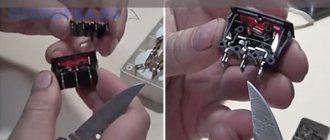
- Disassemble the surge protector housing by unscrewing the mounting screws;
- Unsolder the button and remove it from the filter housing. The button is held in the housing by plastic clips, which should be carefully squeezed out.
- Disassemble. To do this, you need to disconnect the key by picking it up with a flat-head screwdriver.
- Take out the contacts and clean off any black deposits.
- Assemble the button. After this, we assemble the button in the reverse order, install it in place and solder it.
If the contacts have burned very badly and melted the plastic of the switch housing, it should be completely replaced.
To do this you need:
- Disassemble the filter;
- Unsolder the button;
- Remove the switch from the housing;
- Install a new one in its place (sold in radio parts stores, costs about 30 rubles);
- Solder the button and assemble the filter housing.
Often the button on the surge protector does not work
due to mechanical damage. The most common case is the breakdown of the latches that hold the switch key in the housing. In this case, it is not necessary to buy a new button - the latches can be restored.
To do this you will need the following materials and tools:
- screwdriver (or drill) and drill with a diameter of 3.5 mm;
- toothpick;
- cotton swab;
- side cutters.
The process itself is very simple:
- A through hole is drilled in the key into which a cotton swab is inserted (it will act as a latch).
- A toothpick is inserted inside the cotton swab for greater rigidity. On both sides, the improvised retainer is trimmed with side cutters so that on each side it protrudes approximately 3-4 mm.
- Now all that remains is to insert the key into the body - to do this, just slightly bend the sides of the seat with a screwdriver.
VIDEO INSTRUCTION
Surge protectors-extenders SVEN
Today in our laboratory we are debuting surge protectors under the Finnish brand Sven, which has been widely known on the Russian market since 2001, mainly thanks to its inexpensive and relatively high-quality speaker systems. Inexpensive batteries for UPSs under the Sven brand are also widespread in Russia. We will begin our acquaintance with the products of this company with a review of three network filters - Fort, Fort Pro and Optima Base.
Description
For the presented extension filters, the manufacturer declares the following characteristics:
Fort series surge protectors are packaged in black cardboard boxes, and Optima Base extension filters are packaged in a plastic bag. The packaging of the filters is very informative; it has a Euro hole for placement on hooks in supermarkets. High quality printing. Boxes with Fort filters include an instruction manual and a warranty card in Russian and English. The warranty period for SVEN filters is 12 months, and the product service life is 2 years.
SVEN Fort
The SVEN Fort surge protector extension cord is made of matte black plastic, which, together with the red switches, looks very nice. Each switch that is turned on is illuminated in red. The switches are located in niches, which prevents accidental pressing. The surge protector sockets are protected by curtains. On the back of the case there are slots for wall mounting, which is possible in two positions - down with the switches and down with the wire. In the latter case, the inscription SVEN and the labels for the protection and grounding indicators are upside down. One can only guess what prevented us from making two more slits in the back wall. There are two indicators on the front panel: one of them lights up green when grounding is connected, and the other indicates the serviceability of the protection, for some reason red. When connecting a PlugIN adapter, it takes up two sockets and can only be installed in one position (see photo below).
The internal structure of the surge protector is traditionally a protection board with three varistors, five switches and sockets, respectively. Plus another larger general switch and a 10A reusable automatic fuse. Switches break both live wires, but the fuse only breaks one. All elements of the surge protector are connected by soldering. Residues of soldering flux are observed in the soldering areas; other manufacturers usually wash them off with a special solution. Current-carrying wires run close to the socket buses. If the busbar gets hot, it can melt the insulation and cause a short circuit.
No high-frequency interference filter was found in the device. But thermal protection was discovered - a thermal fuse in the same heat-shrinkable tube with a varistor.
According to the manufacturer's idea, in the event of increased voltage in the network, the varistor should heat the thermal fuse, which in turn will de-energize the load. To test the protection, we applied a voltage of 320 V to the SVEN Fort input. If this voltage reaches the load input, it is guaranteed to fail, since the voltage on the rectifier capacitors becomes 451 V, and no one installs capacitors at a higher voltage. The typical capacitor rating used in household equipment is 400-450 V. After 10 minutes of operation, we did not detect any heating of the varistor and, accordingly, no activation of the protection. The protection uses a thermal fuse with an operating temperature of 105°C. We heated it with a soldering iron to about 150°C, the thermal protection did not trigger.
Testing under a load of 2400 W showed slight heating of the power cord, and when the load increased to 3400 W, the automatic fuse tripped. The contacts of the load plug and the power cord were slightly warm. With a load of 2400 W, the voltage drop on the extension filter was about 3 V. The transformer PlugIN adapter inserted into the filter, which has thin leads, did not fall out when the filter was turned over, but was held insecurely. It is possible that over time, due to mechanical influences and the occurrence of specific physical processes (heating and cooling), the fixation of such devices will be even less clear.
Tools and materials
Before connecting an outlet with a single-key switch (and grounding), you need to prepare a simple set of tools and materials. The kit includes:
- at least three screwdrivers: indicator, flat and Phillips;
- electric drill and drill bit;
- four-wire cable;
- knife with a thin blade;
- mounting box;
- side cutters (nippers);
- pliers;
- insulating tape.
All tool handles must be securely insulated.
Making an extension cord: step-by-step instructions
As a rule, the manufacturing process does not take much time, so if you have all the necessary elements and tools, you can make an electrical extension cord in 15 - 20 minutes. To do this, follow these steps:
- Disassemble the fork; as a rule, it is unscrewed with one or more bolts, but the design may differ in different models. Rice. 1: Disassemble the plug
- Cut the electrical cable; to do this, remove the required length from the point where it is connected to the plug contacts to the point where the extension cord exits the plug. It should be noted that at the exit point the cable must have both layers of insulation, so you should not strip the top layer of dielectric with a margin. Fig 2. cut the cable
- Prepare a wire to connect to the plug terminals. To do this, step back about 1 - 2 cm from the edge of each core and carefully trim the rubber insulation. Rice. 3. Strip the ends
Be careful not to cut the core wire, otherwise this will reduce the cross-section and may lead to further overheating at the attachment point.
- Depending on the method of fastening in the plug contacts, prepare the ends of the wire (make loops, twist into one core, etc.).
- Do all these procedures for the second end of the wire.
- Connect the ends of the wire to the ends of the plug and assemble it. Figure 4: Connect the wire to the plug terminal
Please note that the assembled fork should not have any gaps - both parts fit snugly against each other. If you find a gap, disassemble it again and eliminate the cause of the unevenness. Where it exits the plug, the extension cord should fit snugly against the edges; if its diameter is not enough, add a little electrical tape.
Rice. 5: Assemble the fork
- Disassemble the electrical outlet or outlet block, depending on what you are connecting. Rice. 6: Disassemble the socket block
As a standard, they are equipped with one bolt in the center of the socket, but if the cover does not budge, you should inspect the structure for the presence of additional fastening points.
Rice. 7: standard socket mounting point
- Connect the ends of the wires to the corresponding outlet terminals of the electrical extension cord. Rice. 8: Connect the wire to the socket terminals
If you are making a device for a three-wire network, be sure to follow the wire markings. Especially for the ground wire, otherwise you may apply voltage to the body of the device.
- Reassemble the socket in reverse order, the electrical extension cord is ready.
Rice. 9: assemble the socket - the extension cord is ready
Please note that when connecting certain parts, contact must be ensured using special clamps, sleeves or by soldering. It is under no circumstances allowed to ensure contact only by screwing the wire to the lamellas or other parts. After making an electrical extension cord, do not rush to plug it into the outlet; first check its serviceability using a multimeter.
Checking the serviceability of the electrical extension cord.
To check the functionality of the carrier, you will need a regular multimeter or megohmmeter. The whole process can be divided into checking the integrity of the line and checking the insulation. Initially set the multimeter to dialing mode:
- Connect one lead of the multimeter to the socket of the outlet, and touch the second lead to the plug of the electrical extension cord. If the device does not report a circuit, touch the second prong of the plug.
- Hold the multimeter probe on the same contact of the plug where the device showed the circuit, and check other sockets in the block. Their contacts of the same name should also provide a circuit for the continuity of the electrical extension cord.
- Check the second pair of contacts of the electrical sockets and the output of the extension plug; they should also show the presence of a continuity circuit.
- If you are using a three-wire extension cord, make the same connection between the grounding pins on the plug and each outlet.
Rice. 10: principle of continuity of the extension cord
The presence of a circuit between all of the listed terminals indicates that the extension cord can normally transmit electricity in a closed circuit. But, in addition to the circuit, it is necessary to ensure the condition of the insulation. What is a megohmmeter used for? But if you don’t have one, you can use the same multimeter in insulation measurement mode. For industrial purposes, measuring insulation with a multimeter is not permissible, but for domestic needs this will be quite sufficient.
During the measurement process, you need to set a limit on the maximum resistance value in kOhms or MOhms. Apply the probes to the phase and zero terminals on the plug; if the resistance is more than 500 MOhm or infinity, its level is sufficient for normal operation of the electrical extension cord.
Rice. 11: measurement of resistance between phase and zero
If the resistance approaches zero or is tens of ohms, you have broken the insulation somewhere and you need to double-check all electrical contacts in the extension cord. If there is a grounding contact, the resistance value must also be checked between phase - ground and between zero - ground.
Rice. 12: ground resistance measurement
If during testing you have determined the integrity of the phase, zero and ground circuits in the manufactured electrical extension cord, as well as a sufficient level of resistance between all terminals, then such a carrier can be safely used to connect equipment.
How to make an electric baby carrier with a switch.
I have had cases where I included something in the carrier, but this device or tool did not work. And then I start looking for what is the reason - the power tool or the carrier. But if there is a backlit button installed on the socket block, then it becomes visually visible whether there is voltage in the carrier. And the search circle is significantly reduced.
So let's install a backlit button in our carrier. You can, of course, take the easier route and buy a ready-made socket block with a button in the store. But the installation process itself is important to you and me, so we will install the button ourselves.
At a hardware store we buy a backlit button KCD3. When purchasing, pay attention to the technical specifications. It is necessary that the button be designed for a voltage of at least 220 V, usually they say 250 V, the current is 16 A and the degree of protection must be no less than IP - 55.
There will be three contacts on the button. Two are needed for connecting (switching) power, and the third is for backlighting.
To install a button in our socket block, we need to cut a corresponding hole for it. To do this, you can use a drill and a small file. We drill several holes, and then use a file to adjust them to the required dimensions. The main thing is not to overdo it so that the button does not dangle in the case.
The button should be marked where the input and output are, and where the contact for the backlight is.
Now we connect the button as follows: we connect the wire from the contact terminal of the socket to the backlight contact. If you have PVA, then you need to connect the blue wire. Now, so to speak, we connect the phase conductor to the “input”, and connect the wire from the “output” to the second contact terminal of the socket.
The third wire, as you remember, sits on our grounding. Close the cover of the socket block and you can check.
If you turn on the button, it should light up, thereby signaling that there is voltage in the outlet. When you turn it off, the backlight will go out, and accordingly the sockets will not work.
Attention. With this button connection scheme, the circuit breaks on only one wire, that is, a phase may be present in the sockets. If you need to completely remove the voltage from the outlet, then you need to install two buttons. Or if you buy a block of sockets with a button already installed, then there should also be two of them.
To consolidate your knowledge, I advise you to watch the video clip.
Good video on how to make a baby carrier with a switch
How to fix an extension cord at home
That's all I have. I hope you found the article useful. Click on the social media buttons and subscribe to updates. Ask your questions in the comments. Bye.
Sincerely, Alexander!
How to connect a switch. How to connect a switch to a light bulb
To connect the light bulb to the switch you will need:
- switch
- electrical wire
- distribution boxes
- electric indicator screwdriver
- wire cutters and pliers
- insulating tape
- fastener
- socket box
- hammer drill
The diagram for connecting the switch to the light bulb is as follows: all the wires in the apartment, as well as the wires coming from the switch and the lamp, must be connected to the junction box. The working conductor of the network is connected to the working conductor of the light bulb through a switch so that one wire of the socket is connected to the neutral conductor of the network, and the second to the conductor of the wire that comes from the switch.
The diagram for connecting a light bulb to a switch is quite simple. By following this diagram, the switch will be connected correctly.
Extension joint when broken or extended
When using an extension cord for a long time, sometimes the cable shorts due to kinks, blows once applied to the cord, etc. Maybe you wanted to increase the length of the extension cord. Let's look at how to connect an extension cord with your own hands.
To begin, unplug the power cord. If the cable is shorted, it will be immediately visible, cut off 10 cm on both sides from the epicenter of the short circuit, and wipe off the soot. We remove the top insulating sheath of the cable 5 cm, clean the wires 1.5 cm on both sides.
We twist the two bare wires together as tightly as possible, preferably without gaps for good contact, this will prevent the connection from heating up under load. We insulate the twist with insulating tape, and do the same with other wires; be sure to wrap both twists with insulating tape, for the elasticity of the twist and strength.
Some people prefer soldering wires; this method is better than twisting. Soldering of wires and insulation is carried out in the same way. When extending the cable, the same work is done
How to make a surge protector directly, without a button
If the old button has completely failed and you don’t have a new one at hand, you can connect the surge protector directly, turning it into a regular extension cord.
To do this you need to do the following:
- Open the mains voltage filter housing by unscrewing the mounting screws with a screwdriver;
- Unsolder the wires from the button and solder them according to color, bypassing the button;
- Insulate the joint with insulating tape or heat shrink;
- Assemble the extension cord and test its functionality.
To avoid the surge protector switch problems described in this article, consider the maximum power rating of the connected load and the maximum load current when selecting a device.
VIDEO REVIEW » alt=»»> If the total power of the equipment exceeds the maximum permissible filter power, then you should opt for a more powerful model.
I welcome you, dear readers, to my website. And today we will talk about how to make an electric carrier with a switch with your own hands.
Agree with me that at home it is very difficult to do without an extension cord. I use this miracle of technology every day. My computer and all the other components for it are included in the carrier with a block of four sockets. However, I think it’s the same for many people. It’s unlikely that anyone at home has a place where there are three or four sockets at once.
And if the house is also undergoing renovation, then there is no way to do it without an extension cord. Since you will need to connect the power tool in any case. And if several people are doing the repairs, then carrying one socket will not be enough for them. You need to make an extension cord with several sockets at once. Because if people work in turns, it will take too much time.
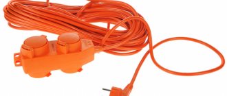
You can, of course, take a simpler route, just go to any hardware store or market and buy several carriers at once. By the way, recently carriers in the form of a coil of wire wound on a reel have appeared on the market.
But such coils are not always convenient to carry with you, and besides, if you need to turn on something powerful, such as welding, then all this wire must be completely unwound from the reel.
Now imagine if you have 50 meters in a bay and all this wire is spread out around the house or apartment, or worse, in one room. It will simply be difficult for you to move without getting entangled in these networks.
Therefore, I suggest you make a carrier with your own hands using available materials. The price will be much cheaper than the store one, and the reliability will be no worse, and quite possibly even better.
Accessories for assembling an electric carrier.
In order to assemble a good and reliable carrier, you first need to decide what devices you will include in it, and calculate the total power.
But if there are no serious loads, then you can assemble the carrier using the simplest components.
Let's start with choosing a wire. If the total load of all devices does not exceed 2 kW, then for carrying you can use a wire with a cross-section of 1 mm 2. And the socket and plug must withstand a current of 10 A.
Usually the manufacturer writes on the body of their products what voltage and current they are designed for, so I advise you to pay attention to this when purchasing.
If the load is about 3 kW, then you need to take a wire with a cross-section of 1.5 mm 2. And the socket and plug must withstand a load of 16 A.
If the load is within 5 kW, then the wire must have a cross-section of at least 2.5 mm 2. But the current with such a load will be about 23 A. So you need to buy the appropriate type of plug and socket.
Now, as for the brand of wire. The fact is that carriers very often have to be twisted and untwisted, so I advise you to take only PVA wire.
The wire of this brand has a stranded core and good insulation, which makes it flexible and will last a long time. And wires with a monolithic core are not suitable for carrying.
List of materials for making the carrier yourself:
- Collapsible electrical plug (designed for the power you need);
- Socket or block of sockets (several sockets);
- Wire of the required length and appropriate cross-section;
- NShVI lugs for crimping stranded wires (although if you carry small loads, you can do without lugs).
- screwdriver;
- pliers;
- press jaws;
- knife or special device for stripping insulation from wires.
Correct connection of the switch. At what height should the light switch be placed?
Before connecting the switch, you need to establish the level at which it will be located.
Sockets and switches can be installed at any height. During the Soviet period, sockets were located at table level, and switches were located quite high. Now the sockets are placed low. This is due to the large number of constantly connected devices and the reluctance to pass bundles of wires in plain sight. Switches also began to be mounted much lower, at a distance of about 1 m from the floor. Typically, this is to ensure that turning lights on and off in rooms is easy for short people. You can install the switch in the most convenient place for you.
Causes of extension cord failure and how to detect them
Such specimens have fragile wires that are easily susceptible to mechanical stress.
Conventionally, an extension cord consists of three parts - a housing with sockets, an electrical cord and a plug. There are two types of devices available for sale:
- With the simplest design. Such extension cords supply current to electrical appliances using two wires - zero and phase, and do not have a switch button.
- Models with additional parts that have a power button; the cable can be two- or three-wire (zero, phase and ground).
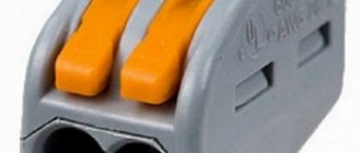
Inside the main block there are two current-carrying busbars (yellow metal plates that are inserted into the grooves of the housing). Their rounded areas are aligned with the socket connectors.
The three-phase extension cord has an additional grounding bus.
The reasons for device failure may be different. Most often, they are associated with mechanical stress and violation of operating rules.
In other words, over time, the wire breaks and breaks. Mechanical failures occur when the cord is squeezed, bent at an acute angle, or pulled sharply. This also includes deformation of the tires when the consumer device is repeatedly turned on and removed from the socket.
Why can't two extension cords be connected together?
Statistics show an impressive figure: about 4,000 house fires are caused by improper use of baby carriers.
The most common problems are insulation damage, circuit overload, short circuit and improper operation. Connecting two extension cords together is an example of improper use of these accessories. Each year, approximately 50 people are killed and 270 injured as a result of these errors. And although it seems that connecting two extension cords to each other is the most correct and only solution, it is still not the best idea. The security of your home is much more expensive than the cost of carrying a longer cord. The main task of an extension cord is to transmit current over a distance equal to the length of the cable.
Once the two carriers are connected, the resistance increases. The cord overheats and the insulation becomes damaged, which may result in electric shock or fire. As the resistance increases, the voltage drops, causing the household appliance or power tool to not operate at full capacity. The solution is to buy an extension cord with a cord of suitable length.
Method for detecting a broken cable section
A way to detect a possible break area is to use a device that will indicate that it is on or off. A radio receiver, any table lamp, and much more can serve as testing equipment. We connect the selected device into the carrier and then, starting from the plug, every 5 cm we begin to bend the wire in different directions. When the wire is bent in a certain place, the device will turn on. Therefore, this is where the cliff area was discovered.
8
Results
Illuminated switches are an extremely convenient and practical device that can be used in an apartment or house. Its installation is quite simple and anyone can do it, but the process requires a lot of concentration. The choice of one- and two-key models adds variability - with one or two buttons you can turn on all the lights in the room. It is very convenient and practical.
Scheme and principle of operation of backlight using LED
If the lighting device contains LEDs, the backlight of the homemade switch will not work at all due to the high resistance of the LED lamp. A regular indicator screwdriver or multimeter will help determine the nature of the conductors - where is the zero and where is the phase.
It can be ready to use and does not require any action to connect it. The efficiency of the circuit will not change, and both LEDs will shine at once with the same brightness.
Pass-through switch with backlight. Any LED or diode in this circuit will do. The LED light bulb is connected to the switch terminals.
The only exceptions may be exclusive models from foreign manufacturers. This scheme has a drawback that concerns the installation process. Check that the connection is correct. Video: how to connect a single-key backlit switch Installation and connection of switches with several keys In everyday life, switches with several keys are often used.
Recommended: Safety requirements for measuring insulation resistance
How to install a switch.
We unscrew the screws securing the switch to the socket box and pull out the device body from the wall. The installation of each device is completely similar to that described above. Regardless of the type, installing an illuminated switch is the same.
This data can be used for calculations on a calculator if the parameters of an LED or neon bulb are unknown. When installed in a socket, it is connected parallel to the current-carrying wires. You will know whether the socket is energized or not. The diagram of the presented device does not contain any complications.
How to connect an illuminated switch?
An LED switch illumination circuit can be installed if the lamp uses incandescent light bulbs. There are as many starters as there are fluorescent lamps in a luminaire.
The end of the output is formed into a ring and secured to the second terminal of the switch. So you don't have to worry about your energy costs going up because backlit switches consume very little energy. Or for lighting - when it gets dark, the light bulb will turn on on its own and vice versa. (makel) Installation of double illuminated switch + diagram
How to properly use a homemade extension cord
When using a homemade extension cord, several mandatory requirements must be met.
- There should not be any damage on the cable, and if it does appear, it must be insulated. Isolation is performed when the extension cord is unplugged from the outlet.
- If a plug or socket fails, it must be replaced. They should be protected from moisture and avoid excessive overloads.
- When operating at maximum loads, the cable must be completely unwound to avoid overheating.
{SOURCE}
How to make a surge protector directly, without a button
If the old button has completely failed and you don’t have a new one at hand, you can connect the surge protector directly, turning it into a regular extension cord.
To do this you need to do the following:
- Open the mains voltage filter housing by unscrewing the mounting screws with a screwdriver;
- Unsolder the wires from the button and solder them according to color, bypassing the button;
- Insulate the joint with insulating tape or heat shrink;
- Assemble the extension cord and test its functionality.
To avoid the surge protector switch problems described in this article, consider the maximum power rating of the connected load and the maximum load current when selecting a device.
VIDEO REVIEW » alt=»»> If the total power of the equipment exceeds the maximum permissible filter power, then you should opt for a more powerful model.
A surge protector is a useful device that protects sensitive electrical appliances from power surges and impulse noise.
Externally, a household filter resembles a regular extension cord, but it is additionally equipped with a built-in unit that absorbs all frequency fluctuations.
To protect against large surges, the device is equipped with a fuse, which in case of critical overloads instantly disconnects electrical appliances from the network.
Like any other devices, surge protectors can break down during intensive use.
One of the most common reasons for the failure of a surge protector is a breakdown of the on-off button, or rather, burning of the contacts inside this button.
First, when turned on, it begins to spark, heat up and make strange sounds, and over time it stops working altogether. If the filter is used frequently, the button may wear out physically or become mechanically damaged.
Attention! If the surge protector button begins to spark, heat up and/or crackle, further operation of the device is unsafe! You should immediately disconnect the filter from the mains to avoid fire! For safe operation of the filter, you need to check the condition of the switch contacts and, if necessary, clean them of carbon deposits.
Let's look at the button diagram of a typical surge protector:
As can be seen from this diagram, there is nothing complicated in the design of the surge protector power button , so you can repair it or replace it with a new one yourself.