Rules for marking live parts according to the PUE
To ensure clarity, simplicity and ease of recognition of individual parts of the electrical network, in accordance with clause 1.1.30 of the PUE, all electrical installations must have an alphanumeric and color designation. Moreover, the presence of one of these designations does not eliminate the need for the other.
And the only relaxation is the possibility of applying a designation not along the entire length of the conductor, but only at the connection points, as shown in the video.
Wire color coding
Marking wires by color is the most visual and allows you to quickly determine the purpose of any wire. This marking can be done by selecting wires with the appropriate core insulation color, by applying paint to the busbars, or by painting or applying special colored tape at the core junctions.
Moreover, the paint on the tires may not be applied along the entire length, but only at the connection points or at the ends of the tires.
- If we talk about the color designation of wires and cables, then we should start with the phase conductors. According to clause 1.1.30 of the PUE in a three-phase network, phase conductors must be marked in yellow, green and red. This is how phases A, B and C are designated respectively.
- The instructions for a single-phase electrical network suggest the designation of the phase wire in accordance with the color of which it is a continuation. That is, if a phase conductor is connected to phase “B” of a three-phase network, then it should be green.
Note! In a single-phase network in an apartment or house, you often do not know which phase your phase wire is connected to. In order to comply with GOST, you do not have to find out this at all. It is enough to designate the phase conductor with any of the proposed colors. After all, for a single-phase lighting network, it does not matter at all which phase your conductor is connected to. The only exception is the lighting network, which uses two different phase conductors.
- As for the neutral conductors, they should be blue in color. Moreover, the color of the neutral core does not depend on the three-phase, two-phase or single-phase network in front of you. It is always indicated in blue.
- Wire markings with a yellow-green stripe indicate a protective conductor. It is connected to the housing of electrical appliances and provides safety from electric shock if the insulation of electrical equipment is damaged.
- If the neutral and protective conductors are combined, then according to clause 1.1.29 of the PUE, such a wire core should have a blue color with yellow-green stripes at its ends. To make such markings with your own hands, you just need to take a blue wire and mark it with paint on its end seals or use colored electrical tape for this.
- As for DC networks, the positive core of a wire or bus should be indicated in red, and the negative core in blue. In this case, the designation of the neutral and protective conductors corresponds to the markings in alternating current networks.
Colors in electrical wiring
Before the introduction of color standards, only 2 colors were used, which complicated the work of electrical power personnel. This approach is now considered outdated. In networks up to 1 kV, the PUE sets the colors for the neutral wire and ground. The phase must always be externally different from zero to avoid accidents.
Phase
The wire that is energized relative to the neutral is called a phase. In low-voltage networks designed in residential areas, the voltage is single-phase, transmitting electricity directly to consumers.
According to the PUE, one of the colors approved by the standard, but different from green-yellow and blue, should be used.
Neutral
The zero (neutral) cable is used to close the electrical circuit and reverse the flow of current. The potential of this wire is zero, so in normal network conditions touching the neutral is harmless. It is marked with blue color and the letter N.
Grounding
The neutral wire, called “ground,” protects the network from overvoltage. In the event of an emergency mode, a short circuit current exceeding the rated operating value will go to ground directly or through protective equipment.
Checking the correct connection
Unfortunately, not all electricians strictly follow the standards and make mistakes in choosing a conductor when making connections. Therefore, when hanging a chandelier, installing a socket or other electrical installation device, it is better to additionally check whether the insulation of each core corresponds to its purpose.
For identification, installers use two methods: the first is checking with an indicator screwdriver, the second is using a tester or multimeter. The phase is usually determined with a screwdriver, and neutral and zero are determined with measuring instruments.
How to use the indicator?
Even such simple devices as indicator screwdrivers are different. Some of them are equipped with a small button, others are triggered automatically when a metal rod and a current-carrying conductor or contact are connected.
But all models without exception have a built-in LED that lights up under voltage.
A screwdriver is a convenient tool for identifying the phase conductor. To find out whether the wire is working, use the metal blade of a screwdriver to gently touch the exposed wire.
If the LED lights up, the wire is energized. The absence of a signal indicates that it is ground or zero.
The verification procedure is performed with one hand, therefore, the other is free. It is better to also use it - for example, to fix wires. But it is strictly forbidden to touch the exposed parts of conductors or metal objects located nearby (pipes, fittings) with your second hand.
Other marking methods
Of course, the variety of electrical installations is not limited only to AC networks. According to the current standard, the positive and negative conductors in DC circuits, designated L+ and L- in the diagram, respectively, have brown and gray insulation. Previously, it was customary to designate the positive conductor in red, while the negative conductor could have any marking, although, as a rule, its insulation was black. According to current standards, the middle conductor is indicated in blue, just like the grounded pole conductors.
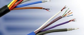
Sometimes you may encounter the fact that all the wires in a cable have the same color. However, if you take a closer look, it turns out that the insulation has stamping in the form of one or more stripes, or letters and numbers. Also, in some imported cables, the cores differ in shape; they can be flattened on one or more sides.
Marking color standards
A system of marking colors was developed and approved in the Electrical Installation Rules (PUE). A color and alphanumeric decoding of each core was determined, which must be observed along the entire length of the electrical wiring. If it has been laid previously, without compliance with approved standards, identification at the inputs and outputs, as well as at the connection points, is allowed. For this purpose, multi-colored heat-shrinkable tubes and cable markers are used (in extreme cases, electrical tape of a similar color).
Single-phase alternating current network
For alternating current up to 1000V with a solidly grounded neutral, which includes most residential buildings and administrative buildings, generally accepted colors are used. Neutral wire:
| “Zero” (N) - blue; |
| "Earth" (PE) - yellow-green; |
| The combined working and protective zero (NPE) is yellow-green with blue marks at the ends. |
According to modern requirements, it is prohibited to use NPE grounding, as it is unsafe . At the moment, the combination of working and protective zeros is extremely rare, as a rule, in outdated wiring.
For phase connections there is a range of acceptable colors:
| Black |
| Brown |
| Red |
| Grey |
| Violet |
| Pink |
| White |
| Orange |
| Turquoise |
You may notice that blue, yellow and green are not . They used to be there, but they were excluded on purpose so that the color would not match the zero and the “ground”.
In practice, you can find a phase with yellow or green insulation, but in no case yellow-green (!) .
Often in everyday life, single-phase circuits are a branch of a three-phase one; in this case, the insulation of the phase core must correspond to one of the three phases to which it is connected. If the color of the cable does not match, it is recommended to mark it with a special marker or cambric.
Cable tags
> Theory > Cable tags
For the correct installation and operation of electrical wiring and other devices, you must have at least minimal knowledge in the field of standards for the construction of cable lines and electrical installations. There are many provisions and instructions governing the actions of an electrician and installer when working on electrical lines of various voltages. Such documents also include the Rules for marking wires on the main line and in the distribution cabinet. This article discusses the types of tags for cable markings, as well as the conditions under which the label should be on the surface of the wire.
Types of cable tags
Cable marking can be carried out with factory-made or self-produced tags, but their form must be strictly observed within the framework of the regulations. Based on this standard, there are several types of tags used to mark cable lines, these include:
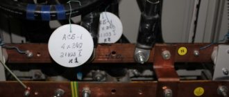
- Square badges with holes for fastening. These tags indicate lines with voltages up to 1000 V, most often these are routes for household purposes;
- Round tags are designed to identify electrical cables transmitting over 1000 V; these are industrial lines that require a high level of safety during installation and operation;
- To mark a low-voltage wire or control network, you will need a triangular-shaped tag with all sides equal to each other.
All of the listed types of tags can have different sizes, depending on the amount of information that needs to be written on the surface. To prevent mechanical damage to the wire during installation of the mark or during operation, the material for the manufacture of this product must be soft, such as plastic, leather or polystyrene. If metal is used, its edges must be processed to eliminate sharp corners and jagged edges that could damage the outer sheath of the cable.
According to the PUE, each cable line, regardless of the method of its installation and location, must have its own marking with a number or name. If there are several parallel branches in one cable route, then each of them must have a personal tag indicating all parameters and direction.
These Electrical Installation Rules also state that connecting couplings and wires, end caps and inputs to distribution boards must be marked with tags. In front of each circuit breaker in the cabinet there must be its own label, which indicates the voltage height, cable cross-section and installation date.
All marking elements are signed with a special pencil, the ink of which is not afraid of exposure to precipitation and is durable, not changing its structure during elevated temperatures.
The tags themselves, since they are made of synthetic material, are also not subject to corrosion and destruction from external factors, which makes them universal for use indoors and outdoors.
When cables are located in a closed line, box or corrugation, marking with tags is carried out at least every 50 meters, while fastening the parts is carried out over the channel by installing plastic clamps or copper wire. The fixation must be reliable, since during operation of the electrical installation its movement or other mechanical impact is possible, the tags should not be damaged or completely torn off from the main line.
Requirements for inscriptions on tags
Sip cable: types and characteristics
Tags on the cable, secured with clamps or threaded through the wire, must be signed in a certain way; this rule is regulated by the rules of the PUE. In accordance with this document, the following data is applied to the label:
- Cable or line number. This is information that contains data about the direction of the highway, what it feeds, and what level of protection is required. During the wiring installation process, an object passport is drawn up, which indicates the buildings or premises powered by this line. They are assigned numbers, which will subsequently be written on the tag itself; during the service process, the technician will be able to look at the markings of the cables and, by comparing them with the object’s passport, understand where this or that line leads;
- Brand and cross-section of wire. Since space on the tag is limited, the designation is written abbreviated, with a minimum number of characters. For example, a vinyl-coated cable with a cross-section of 3*2.5 is briefly designated VVG-3/2.5;
- Line voltage. This is a mandatory parameter, since it is not clear from the outer sheath of the cables what voltage the current flows through it, respectively, and what level of protection is required during repair work;
- The beginning and end of cable lines. For more accurate information about possible losses on the main line after its installation, a designation of the total length is applied. After reading the data, the technician servicing the wire line will be able to accurately calculate the resistance and level of voltage loss in the network.
All of the information listed is basic and mandatory. It is not prohibited to place additional information on the tag that characterizes the electrical main, for example, the date of laying. In addition, when placing a tag on the coupling, it is necessary to place the date of installation of the wire, since the coupling has its own resource, which will be calculated based on this indicator.
Inscriptions on metal tags are most often made by engraving with a special pencil or indelible paint. Plastic products are signed with a permanent marker or indelible paint. Also, when placing a tag using wire on a highway, it is necessary to additionally protect metal objects with bituminous composition or any other paint, otherwise the wire will rust and collapse, and the tag will be lost. Nylon thread is best suited for fastening; it is not afraid of temperature changes and high humidity.
Tag for threading onto wire
Recently, to indicate the cable on the line, many electricians began to use stickers that already have inscriptions informing about the voltage, as well as empty spaces in which additional data is written. Such stickers are very convenient, since the master does not waste time making markings, but simply glues the element onto the finished tag and continues installation.
Rules for placing tags on devices
When installing in closed channels or collectors, the tags must be located in inspection wells, regardless of their distance from each other. The part is attached on both sides of the collector to each of the route branches. It is also necessary to mark the turning sections of the line on both sides, indicating the direction of rotation and degree.
Color coding of wires and busbars
Hello, dear readers and guests of the Electrician's Notes website.
When carrying out electrical installation work, the question of color marking of wires is often raised.
Earlier, so to speak, in “stagnant” times, only white wires were used, less often black.
Therefore, determining phase or zero in an electrical assembly took quite a lot of time. We had to resort to voltage indicators and various analog and digital devices.
To avoid this, you need to bring the color marking of wires and buses to a single standard.
And as always, let’s turn to the regulatory documents, namely the PUE, Chapter 1, clause 1.1.29. and clause 1.1.30. It clearly states that identification of wire cores and busbars by colors or digital designations must be used in accordance with GOST R 50462-92.
According to GOST R 50462-92, clause 3.1.1, the following colors can be used to identify conductors and busbars: black, brown, red, orange, yellow, green, blue, cyan, gray, white, pink, turquoise.
- neutral working conductors (N) must be blue
- combined neutral working and neutral protective conductors (PEN) must have blue color along the entire length and yellow-green stripes at the ends
- neutral protective conductors (PE) and protective grounding conductors must be yellow-green in color
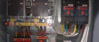
Let me give you a few photographs as an example. All neutral working conductors (N) are connected to the bus (N) and are blue. All neutral protective conductors (PE) are connected to the bus (PE) and are yellow-green in color.
And all other colors except cyan (blue) and yellow-green can be used as phase conductors.
Colors for 220V and 380V networks
Installation of single- and three-phase electrical networks is facilitated if the wiring is made with multi-color wire. Previously, a flat two-core white wire was used for single-phase residential wiring. During installation and repair, to eliminate errors, it was necessary to ring each core individually.
The production of cable products with colored cores in different colors reduces the labor intensity of the work. To indicate phase and zero in single-phase wiring, it is customary to use the following colors:
- red, brown or black – phase wire;
- other colors (preferably blue) – neutral wire.
The phase markings in a three-phase network are slightly different:
- red (brown) – 1 phase;
- black – 2 phase;
- gray (white) – 3 phase;
- blue (cyan) – working zero (neutral)
- yellow-green – grounding.
Domestic cable products comply with the standard for core coloring, so a multiphase cable contains differently colored cores, where the phase is white, red and black , the neutral is blue , and the ground is yellow-green conductors.
When servicing networks installed according to modern standards, it is possible to accurately determine the purpose of the wires in the junction boxes. If there is a bundle of multi-colored wires, the brown one will definitely be phase. The neutral wire in distribution boxes has no branches or breaks. The exception is branches to multi-pole switching devices with complete circuit breaking.
Requirements for types and methods of attaching tags
In addition to the placement of tags, all information about the markings produced on cable lines and communication devices is recorded in a special journal. Such records are regularly updated depending on changes that have occurred in the network structure.
Ley Line Markers
In accordance with GOST, plastic plaques are made in square, round or triangular shapes. They are used in open areas of cable routes and circuit components. The tags have two holes through which the wire or core should be threaded, after which it is securely clamped and fixed in the desired position.
For lines whose voltage does not exceed 1000 V, square tags are used. If the operating voltage is above 1000 V, then round plastic plaques are used. Triangular products are required for control power lines.
Tags for low power circuits
For such purposes, small plates made of polymer materials can be used, which indicate information about the electricity consumption of the circuit subscriber and other data.
Marking of wires and cables according to the rules
Correct marking of wires and cords can greatly facilitate the installation and repair of any electrical networks. After all, correct marking will not only facilitate the installation process itself, but will also allow you or any other person to determine their purpose by simply looking at the junction box, panel or wires.
It is for these purposes that the marking of wires must be carried out in accordance with the uniform rules that are given in the “Bible” of any electrician - PUE (Electrical Installation Rules).
Blog
With the help of this material, I want to help newcomers and old-timers understand and understand the features of color marking of wires and cables in accordance with the standards of the Republic of Belarus and not only.
Recently I had the opportunity to connect an apartment switchboard, which came with about 30 cables, with different color markings for the cores. The joke was that the markings were so different that each electrician (and there were two teams working at the site) interpreted the color markings in their own way.
Naturally, there were some problems, and in one day (as usual) I was not able to connect the shield, since my opinion on the color of the wires did not coincide with the opinion of other electricians. I had to spend another day to ring all the lines for proper connection in the switchboard.
I'll tell you the details...
Some of the most popular cables in Minsk (at the time of 2013-2015), made in accordance with GOST, were stretched to the shield. In the three-core cable VVG-P 3×1.5 and VVG-P 3×2.5, the colors of the cores are as follows:
- green + red + white
Next were the cables (Beltelekabel) with cores:
- white + white with black stripe + white with blue stripe,
- white + white with brown stripe + white with black stripe
There were also more pleasant, “correct” cables based on the colors of the cores (you’ll find out why they are correct a little later):
- yellow-green + blue + white
- yellow-green + blue + black
- yellow-green + blue + brown (although these were not VVG cables, but an installation PVS and a ShVVP cord, which should not be used in stationary electrical wiring, but that’s another story)
Before starting to understand the colors of the wires, I want to note the mistakes of electricians, from which I gained good experience.
Error 1. When performing electrical installation work, cables from different manufacturers with different core colors were used. At the same time, one color could be interpreted differently in different cable cores. For example, in one cable the zero is black, in another cable the ground is black*.
Error 2 . With wires of such different colors, the grounding and neutral conductors were not marked (using electrical tape or heat-shrink tubes). In simple words, you could simply wrap a piece of blue electrical tape around the core, which was taken as zero, and mark the grounding conductor with green-yellow electrical tape.
Error 3 . Another mistake does not relate to marking, but for some reason most electricians often make it. We are talking about a supply of cables for connecting shields. In this case, it is quite difficult to connect beautifully, since some cables are barely enough to connect. This is despite the fact that the connection was made using terminals on a DIN rail.
Never skimp on cable when connecting electrical panels! If you do not know at what height the shield will be installed, leave a cable reserve up to the floor (as I do). The excess cable can always be used as jumpers to connect sockets.
*Terms: ZERO (N) – working neutral conductor, EARTH (PE) – protective conductor
The conclusions I made when connecting the shield are very simple:
- I stopped using cables without green/yellow or blue markings for outlet lines and lighting power.
- Otherwise, I always mark the conductors with electrical tape to indicate ground (yellow-green tape), neutral (blue tape), and phase (red tape for single-phase wiring or yellow, green, red for three-phase wiring).
Somehow, I began to use the “AUTOWIRE” cable less and more, and “KOBRINAGROMASH” more and more. The colors of the latter are in perfect order.
Now let's understand the colors in electrical wiring.
Color marking of wires and cables in the Republic of Belarus
To begin with, you should understand that color marking is an excellent solution to quickly determine to any craftsman (electrician, engineer, power engineer, etc.) what role a particular conductor plays in an electrical installation. But the difficulty is that there is no single and exact rule for all countries and manufacturers.
In each country, the color marking of wires is different and may differ significantly from ours. In Russia, for example, there is so much confusion with regulations that they themselves do not know which rules to adhere to.
In the Republic of Belarus, there are national rules for the construction of electrical installations TKP 339-2011, which partially replaced some chapters of PUE 6. The following points can be found in it:
Let's take a look at the STB IEC 60173 standard, which is referred to in this paragraph:
I would like to draw your attention to four points in this standard:
- It is clearly defined that the yellow-green conductor is EARTH (PE)
- Blue color is ZERO (N)
- Recommended colors for other cores: BLACK or BROWN.
- Colors not recommended for cores: green, yellow, red, gray and white.
Let’s not draw further conclusions, and will continue to study TKP 339-2011:
Again, we are told that the grounding (protective) conductor must be GREEN-YELLOW and designated by the Latin letters PE.
From this point it is clear that ZERO (neutral conductor) should be indicated in BLUE.
And this item indicates what color the phase bars should be designated for a voltage of 400 (380) Volts:
- L1 (phase A) – YELLOW
- L2 (phase B) – GREEN
- L3 (phase C) – RED
We have familiarized ourselves with the paragraphs of TCH 339-2011 related to color marking. However, TKP 339-2011 only partially replaced some chapters of PUE 6. Everything else that is not in the technical code 339-2011 should be found in PUE 6, which is in force in the Republic of Belarus. And in it you can find the following paragraph 2.1.31:
The conclusions for now are simple:
1. On the territory of the Republic of Belarus there are rules for color marking of tires ( YELLOW , GREEN , RED ).
2. According to the colors of the wire cores:
GROUNDING (EARTH) PE – always YELLOW-GREEN
ZERO (neutral conductor) N – always BLUE (BLUE, LIGHT BLUE)
Advice
PHASE (phase conductor) L – can be black, brown, gray, red, purple, pink, white, orange, turquoise. However, it is recommended to use priority colors to designate phases: BROWN (priority for phase conductor No. 1) and BLACK (if there is a brown conductor, priority for phase No. 2).