How to read car electrical diagrams?
In order to understand the contents of the circuit, you need to know the correspondence between the circuit symbols and the real elements of the device. What functions do these devices perform and how do they interact with each other?
Let's define the terms:
- A circuit element is a component of a circuit that performs a specific function in a product and cannot be divided into parts that have an independent purpose.
- A device is a collection of elements representing a single structure (block, board, etc.).
- Schematic diagram (complete) - a diagram that defines the complete composition of elements and connections between them, and, as a rule, gives a detailed understanding of the principles of operation of the product. Schematic diagrams are used to study the principles of operation of products, as well as for their adjustment, control and repair. They serve as the basis for the development of other design documents, for example, connection diagrams (installation diagrams) and drawings.
- Connection diagram (installation) - a diagram showing the connections of the component parts of the product and defining the wires, harnesses, cables that make these connections, as well as the places of their connections and input (connectors, boards, etc.).
- Layout diagram - a diagram that determines the relative location of the component parts of the product, and, if necessary, also harnesses, wires, cables, etc.
- A harness is a set of wires packaged in a certain way into a single whole.
In the electrical equipment diagrams of cars, the schematic, installation, and layout diagrams are combined into one in a simplified form; the simplification concerns the wiring and layout diagrams. In the diagrams, the devices have a design that to some extent corresponds to their appearance, and they are located according to the diagram in the same way (top view) as in reality physically, with a certain simplification. This combination applies mainly to the circuits of cars of early releases. The circuits of modern cars are designed differently, due to the significant complexity of electrical equipment, the layout is carried out separately.
When reading diagrams, you need to know the fundamental principles:
- All connection wires are color coded, which can consist of one color or two (main and additional). Transverse or longitudinal strokes are applied with additional color.
- Within one harness, wires of the same marking have a galvanic connection (physically connected to each other).
- In the diagrams, the wire at the entrance to the harness is inclined in the direction where it is laid.
- Black color, as a rule, indicates a wire that is connected to the car body (ground).
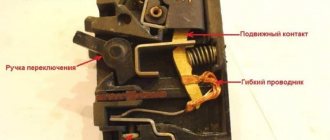
- The positions of the relay contacts are indicated in the state when no current flows through their winding. According to the initial state, the relay contacts differ - normally closed and normally open.
- Some wires have a digital designation at the point of connection to the device, which allows you to determine where it comes from without tracing the circuit. See table.
According to DIN 72552 (commonly used values):
| Contact | Meaning |
| 15 | Battery positive after the ignition key contacts. |
| 30 | Plus the battery directly. |
| 31 | Minus the battery directly or the housing. |
| 50 | Starter control. |
| 53 | Wiper. |
| 56 | Headlight. |
| 56a | High beam. |
| 56b | Low beam. |
| 58 | Parking lights. |
| 85 | Relay winding (-). |
| 86 | Relay coil (+). |
| 87 | Common relay contact). |
| 87a | Normally closed relay contact. |
| 87b | Normally open relay contact. |
| 88 | Common contact 2 relays. |
| 88a | Normally closed relay contact 2. |
| 88b | Normally open relay contact 2. |
List of the most used symbolic drawings:
Also often with a circuit element there is a symbolic drawing explaining which device this element belongs to.
- Alarm.
- Battery.
- Fan.
- Air damper.
- Oil pressure.
- High beam
- Pad wear sensor.
- Egnition lock.
- Sound signal.
- Turn indicator.
- Outdoor Lighting.
- Heated rear window.
- Windshield washer.
- Rear window washer.
- Headlight washer.
- Interior lighting.
- Windshield cleaner.
- Rear window cleaner.
- Headlight cleaner.
- Cigarette lighter.
- Anti-fog equipment.
- Instrument lighting brightness control.
- Reversing light.
- Glass door lifts
- Coolant temperature.
- Brakes.
- Fuel level and reserve indicator.
- Washer fluid level.
- Coolant level.
Designations of circuit elements.
- Switch.
- Diode.
- Lamp with two filaments.
- Lamp.
- Variable resistor.
- Fuse.
- Resistor.
- Relay.
- Zener diode.
- 1.Off (contacts 1 and 6 are closed);
- 2. Switched on “slowly” (contacts 2 and 4, as well as 5 and 6 are closed);
- 3. “Fast” switched on (contacts 3 and 4 are closed).
» /> Three lever switch. This switch consists of several types of contacts. Non-fixed ones are contacts for turning on the washer, a sound signal and a short-term high beam signal (contacts 2 and 6 are closed), fixed ones are low beam (contacts 4 and 5 are closed), high beam (contacts 2 and 5 are closed), turning on the turn signal and turning on the windshield wiper which has 3 modes:
- 1.Off (contacts 1 and 6 are closed);
- 2. Switched on “slowly” (contacts 2 and 4, as well as 5 and 6 are closed);
- 3. “Fast” switched on (contacts 3 and 4 are closed).
How to read electrical circuit diagrams of foreign cars?
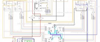
Let's look at an example of reading Nissan car diagrams. To do this, we need to familiarize ourselves with the designation system for elements of electrical equipment on the diagrams. Let's start with the designation of connector contacts. As shown in Fig.1.
Next to the connector picture there is a designation on which side of the connector it is viewed from, the contact side (Terminal Side) (TS) or the harness side (Harness Side) (HS). Please note that the connector outline, where the contacts are viewed from the wire side, is outlined with a line.
Figure 2 and Figure 3 show the designations of the circuit elements, the meaning of which is explained in Table 1.
| Number | Name | Description |
| 1 | Battery | Battery |
| 2 | Fusible link | Fuse installed in the wire |
| 3 | Number fusible link or fuse | Serial number of fused line or fuse |
| 4 | Fuse | Fuse |
| 5 | Current rating | Fuse rating in amperes |
| 6 | Optional splice | The circle indicates that the connection depends on the vehicle version |
| 7 | Connector number | Connector number |
| 8 | Splice | The black circle indicates the connection of conductors |
| 9 | Page crossing | This chain continues on the next page |
| 10 | Option abbreviation | The chain between these marks is present only for all-wheel drive |
| 11 | Relay | Shows internal relay connections |
| 12 | Option description | Shows a variant of the circuit depending on the vehicle |
| 13 | Switch | State of contacts depending on switch position (closed or open) |
| 14 | Circuit | Chain |
| 15 | System branch | Indicates that the connection is going to another system (head lighting) |
| 16 | Shielded line | The line is shielded |
| 17 | Component name | Schematic element name |
| 18 | Ground(GND) | Grounding |
| 19 | Connector | The numbering order of the contacts when viewed from the harness side is indicated. |
| 20 | Connectors | Indicates that the wire has 2 connectors |
| 21 | Wire color | Abbreviation for wire color |
| 22 | Terminal number | Describes the pin number, wire color and signal name |
Table 1.
Color abbreviations
| B=Black | LA = Lavender |
| W=White | OR or O = Orange |
| R = Red | P=Pink |
| G = Green | PU or V (Violet) = Purple |
| L = Blue | GY or GR = Gray |
| Y=Yellow | SB = Sky Blue |
| LG = Light Green | CH = Dark Brown |
| BG = Beige | DG = Dark Green |
| BR = Brown |
In Fig. Figure 4 shows a diagram of normally open and normally closed contacts, this is the state when no current flows through the relay coil.
In Fig.5. The windshield wiper switch is shown in the form of a graphical drawing and two tables. The figure shows a schematic diagram of the internal connections of the switch. The tables describe to us the operation of the switch as a “black box”; it is unknown how the circuit is implemented inside, but at the output the state of the contacts corresponds to those indicated in the table, for the modes:
- OFF - disabled;
- INT - interval;
- LO - low speed;
- HI - high speed;
- WASH - plus turning on the washer.
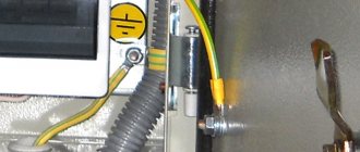
Ground color
The color of the grounding wire, “ground”, is almost always indicated by yellow-green color
, windings that are either completely yellow or light green are less common. The wire may be marked “PE”. You can also find green-yellow wires marked “PEN” and with blue braiding at the ends of the wire at the fastening points - this is grounding combined with neutral.
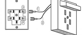
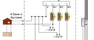
In the distribution panel (DP) it should be connected to the grounding bus, to the housing and the metal door of the panel. As for the distribution box, the connection goes to the grounding wires from the lamps and from the grounding contacts of the sockets. The “ground” wire does not need to be connected to the RCD (residual current device), therefore RCDs are installed in houses and apartments, since electrical wiring is usually carried out with only two wires. Grounding designation on the diagrams:
Conventional ground(1) Clean ground(2) Safety ground(3) Chassis ground(4) DC ground(5)
Connection diagram by wire colors on the radio
High-quality sound makes car trips much more enjoyable, but before you can enjoy your favorite music, you need to connect the radio correctly. This procedure is not very complicated, but due to the fact that each car and radio manufacturer uses its own connectors, some installation difficulties may arise. Connecting the radio according to the color of the wires will come to the rescue.
ISO connector
tell me the polarity of the wires red-black and black
Who cares, ring the device and that’s it...
this is for that darn sharis less—to define—like grass—hay, straw
Most likely the red color was added to the positive wire. But who can vouch for a specific case?
Usually in NORMAL (not Chinese) technology, black is a minus, and indicated by some color is a plus (phase, main). If you need to calculate the plus, apply the connected wires to a cut of a raw potato, the color of the potato will change near the positive contact. *(I don’t recommend checking 220 volts this way)
Black wire with smaller diameter is ground
The color of the wires does not determine the polarity, but makes it possible to make the work of installers and repairmen easier, so as not to get confused with a large number of wires in the device. Have you seen the wiring harness in the car? How many different colors are there? And they don't necessarily indicate plus and minus.
In modern technology (both Chinese and non-Chinese), red is a plus, black is a minus, this is standard. Red-black means positive.
touch.otvet.mail.ru
Precautionary measures
You need to understand that incorrectly connecting the car radio can lead to unpleasant consequences:
- Breakdown of the radio;
- Deterioration in sound quality;
- Wiring short circuit;
- In rare cases, if you connect the radio to the battery incorrectly, you can quickly discharge it. Sometimes this can cause a fire.
In order not to waste your time, you can use the services of a car repair shop, but you need to be prepared to spend a certain amount that the service will charge for connection. In addition, it is worth considering that the cost of connecting a car radio to a foreign car (for example, Toyota) will be higher. The brand of the car radio is also taken into account. Thus, a Pioneer radio (which is the most common and beloved among motorists) will cost less than a Sony or Kenwood radio.
But if a car enthusiast has a desire to understand the device, the ability to spend a couple of hours and, no less important, the desire to save a decent amount of money, then the rest of the article will describe in detail how to connect a car radio according to the colors of the wires.
Instead of an afterword
When buying a used car, it is useful to know how to find an electrical leak and understand its cause. Take a multimeter to inspect your car - you will save yourself from unpleasant surprises, such as a suddenly dead battery, power surges or burnt wiring.
For the same purpose, check the car's history. This can be done directly during a conversation with the seller. It’s convenient to use the Autocode service - monitor information from 13 sources at once: traffic police, RSA, EAISTO, banks, tax and other services. The verification will take 5 minutes.
Afterwards you will find out the actual mileage, number of owners, history of fines, as well as information about theft, participation in an accident, restrictions on car registration and much more. Be carefull!
Having fully studied the online report, it is still worth taking a closer look at the technical nuances of the car when purchasing. And if you are not confident in your knowledge, or it is not possible to go for an inspection, order an on-site inspection service. The specialist will conduct a diagnosis for you and make a detailed conclusion from a professional point of view.
Car radio device options
All radios are manufactured according to the standards of the company that owns them. The aforementioned Pioneer, Kenwood and Sony are manufactured in accordance with the standards of their companies. However, each of them has a standard ISO adapter. Likewise, every machine has a standard plug for this adapter.
Based on this, one of three situations may arise:
- The first option is ideal. All wires in the car have been removed. Everything is connected according to standards and output to an ISO connector. There will be no difficulties in this case. You just need to connect this connector to the radio.
- The second case is when all the wires are routed correctly, but the connector does not fit. In this case, you can purchase a conductor, of which there are a great many sold in specialized stores, connect the radio through the conductor and enjoy high-quality sound.
- The last option: the wires are not brought out into one connector or there are none at all.
The third option is the most problematic, and therefore it is necessary to consider it further.
Color designation of power and other types of cable products
Color marking for SIP or VVG wires comes down to the following rules:
- The yellow-green color will indicate grounding.
- Zero will give a blue or blue tint to the insulating material.
- The phase conductor will be brown or black. But the rules for electrical installations allow the marking color to change to red, gray and even purple shades.
In single-phase networks, where there is practice of using SIP cables, the neutral working conductor can be combined with the grounding conductor. In this case, the marking will look like a yellow-green wire with blue marks, which are placed at both ends of the line during installation.
Three-phase AC networks assume that the SIP cable cores will have the following colors:
- yellow, green and red for phases A, B and C respectively;
- blue color is reserved for highlighting the working zero;
- green-yellow color indicates grounding.
When a SIP cable is used during the installation of power lines, tags with information about the purpose and parameters are additionally attached to it. This marking also allows you to navigate objects where there are many wires of the same type.
Due to the fact that AC networks are created using color-coded SIP wires, not only the work at the installation stage is simplified. Color coding makes it easier to maintain and repair networks and helps reduce accidents. And unpleasant consequences of electric shock can be fatal.
Therefore, the designation of SIP wires and other varieties by color is a necessary precaution and a smart solution that makes the work of installers and users of electrical networks easier.
Wire color identification
For the correct connection to work, it is imperative to know the colors of the wires and their designation. The diagram of the radio wires by color is shown in the photo. On all cars and radios (Pioneer, Sony and Kenwood and others) it is customary to use a certain color to indicate the identity of the wire. It is worth noting that the radio wires differ in color and in the presence or absence of a strip. So, all wires with a stripe are a minus, and those without a stripe are a plus.
- Battery negative – black;
- Battery plus – yellow;
- Ignition plus – red;
- Left front speaker – white and white with stripe;
- Right front speaker – gray and gray with stripe;
- Left rear speaker – green and green with stripe;
- Right rear speaker – purple with a purple stripe;
- Antenna – blue;
- Amplifier – blue with a stripe.
Wire marking
Wire marking is the application of a specific mark to their outer surface to indicate the required characteristics. Marking can be in the form of color markings, inscriptions (numbers and letters), labels or tags.
Important! Letter or numerical markings indicate the material of the shell and cores, cross-sectional area, number of cores inside and other parameters.
The red wire indicates the positive phase or plus. You can remember it by the name “Red Cross”. Black corresponds to the negative phase.
But this designation does not always work: the colors may be different, for example, green and blue, or absent altogether. There are many more colors in three-phase wires:
- The phase is indicated by red, orange, purple or gray colors:
- Neutral - blue or white-blue;
- Grounding - stripes of green or yellow colors.
To avoid mistakes during installation, if in doubt, it is better to check the polarity in advance.
Connecting a car radio
When connecting the radio, you must strictly follow the diagram. To power the car radio, you need to connect the yellow wire to the battery positive. The black wire goes to ground, this is grounding. The red wire is powered from the ignition switch. Ideally, it should be connected so that it is powered only when the key is in the ACC position.
Since installation difficulties arise precisely in the absence of an ISO adapter, all wires must be stripped and then insulated. Stranded copper wires with silicone insulation are ideal. Once the wiring is complete, they can be combined into a standard adapter, but you can also insulate them with the radio wires. The main thing is that the color of the wires of the radio and the car match each other.
There are several other undesirable options for connecting a car radio to a car. Most motorists, not wanting to bother with connecting the yellow wire to the battery, connect it together with the red wire to the ignition switch. This deprives the radio of more power and does not allow you to get high-quality and powerful sound. The same thing happens when the radio is powered from the cigarette lighter.
It happens that the yellow and red wires are connected to the battery. The advantages of this connection are that the radio is always in standby mode and ready for use. However, this method quickly lands him. Therefore, it is worth thinking about what is more important: the operation of the radio independent of the ignition switch or the long-term operation of the battery?
Connecting speakers
The colors of the radio speaker wires have already been described above. Therefore, in accordance with them, you can safely connect any speakers.
Today, almost all car radios are oriented towards 4 speakers: two in front and two in back. It is worth noting that a powerful audio system has a plus and minus output to each speaker. A weak audio system has only a positive output. Therefore, the minus from the column is displayed on the total mass. To get better sound, it is best to observe the plus and minus contacts.
If poor sound quality occurs after installation, there is a simple and effective way to make the connection correctly. You need to transfer the sound to the front speakers, then transfer the sound to one speaker, for example, the left one. Turn on the music at full volume until wheezing or distortion appears. After that, transfer the sound to the 2 front speakers.
If the sound becomes louder and remains of high quality, then the connection is made correctly. If there is no change in volume, or distortion appears, then you need to check whether the plus and minus are connected correctly.
As you can see, connecting a car radio based on the color of the wires is not difficult and, with a careful approach, will take no more than 2-3 hours.
I mixed up the wires once when I connected the speakers. I don’t know how this happened, most likely just carelessness. As a result, the speakers worked out of phase and jammed each other, causing the sound to deteriorate greatly.
In my car, the left speaker of the radio is very wheezing. Maybe this is due to the fact that I connected the radio itself incorrectly? I'm not sure if it's connected correctly, since this was my first time doing this, and I could have messed something up.
Oh, and a puzzle - these wires. About 6 years ago I bought a Pioneer from a friend with protruding wires. He assured me that I would quickly figure it out and everything would connect fine. I struggled all day, but finally did it. I wouldn’t do such an experiment now.
Tell me, why does my car radio turn off when I turn on the headlights?
The drawdown is big. Try putting a thicker wire on the “+” or installing a more powerful capacitor (larger capacity) in the radio.
I connected the radio for the first time in a 1988 Toyota Corolla. The radio was Pioner DEH-X3500UI. The wires in the car were of the old type, you had to buy an adapter and solder the wires from the car to it, the problem with the car was that the wires were not the same color, not according to the instructions, there were pink, blue and all solid colors. I found an old manual on the Internet and found which wire was responsible for it, soldered everything, connected the radio and everything worked, I had no experience in connecting at all, since it was my first car and the first radio I bought, as they say, the eyes are afraid - the hands do!
How many amperes is the fuse in the FUSIOL radio?
Usually they cost either 10 or 15 amps
Guys, hello everyone. I recently bought an Epic 10 year old. It already had a Chinese radio on it, I want to install the original one, but the chips were cut off by some deb......m, who wouldn't mind if you could send me a diagram of how to connect it. by wire color
Well, why is there no mention in the diagrams and texts of the wire (steering wheel cont...), which is intended for connection to possible steering wheel radio control buttons.
How to correctly determine the polarity on wires in a car
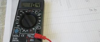
If the voltage on the car is checked, the course is set to search for a constant one. 20W is the correct setting if you are testing the battery. Therefore, you need to adjust the dial to the desired range/setting and connect the probes to whatever component you want to get a reading for.
You may be interested in this Features of inductive reactance
How to check a headlight with a multimeter
Multimeter
To check the headlight wiring, you need to find the ground wire. There are 2-4 wires coming from the connector that connects to the light bulb. Where there are two or three wires, only one of them is ground, while four-wire connectors will have two grounds.
To test the wires on the headlight, you need to set the multimeter to resistance. You can place one of the probes on the ground and the other on the negative pole of the car battery.
Note! If continuity is not read, then there is a problem with the ground wire, meaning it needs to be replaced.
How to Test a Car's Ground Wire Using a Multimeter
To test ground wires, start by measuring resistance. Test along the wiring to check the reading is 5 ohms or less. If it exceeds, you will need to check the wire further. You need to switch the multimeter to constant voltage and turn on any electrical part that is having problems. It's worth double-checking the wire to make sure the reading doesn't exceed 0.05V. If it does, you'll need to use a different ground location or use a tie strap.
How to Check if a Fuse Has Blown Using a Multimeter
Troubleshooting a fuse using a multimeter is extremely easy. You need to set the multimeter to the lowest ohm setting and place the probes on both sides of the fuse covers. Fuses do not have polarity, so the contacts used will not show values.
Circuit breakers
Note! If the resistance value is very low, then the fuse is working perfectly. If the resistance value does not change after connecting the contacts, the fuse has blown.
You can also test the fuse using a test light. You need to turn on the key and touch both sides of the fuse with the tip of the test light. If it lights up, the fuse is good. If it does not light up, the fuse needs to be replaced.
How to use a multimeter from a car battery
If you're having trouble starting your car, one of the most common reasons is a weak battery. This is something that can be easily checked using a multimeter, which will also give an accurate idea of how much charge the battery actually has left. Testing your car battery first is a great way to rule out a likely cult for many electrical problems.
When testing a car battery, you need to check the voltage by setting the multimeter to 20 V DC. It is necessary to connect contacts to both terminals of the battery that match the color. It is better to turn on the headlights to get accurate information regarding the charge.
Important! The headlights must be turned on when the engine is stalled.
In most cases the reading will be somewhere between 11.8 V and 12.6 V. The higher the voltage reading, the more charge there is in the battery. A reading of 12.5V means the battery is almost fully charged, while a reading of 11.9V means the battery should be replaced soon.
You might be interested in: Features of megawatts and kilowatts
Checking the charger
Electronic devices use adapters to convert alternating current supplied from wall outlets to direct current. Once converted to direct current, current flows in one direction, hence the term direct current.
What color is the positive wire on the charger?
Note! One wire is positive, which conducts current to the device, and the other is negative, which completes the circuit. The direction of flow is called polarity and is marked on chargers using a diagram. If there is no diagram on the charger, it is worth checking the polarity.
The color polarity of the charger wires does not matter.
To determine if the charger is fit for use, do the following:
- Connect the charger to a power outlet.
- Turn on the multimeter and set the settings to DC voltage. Most multimeters indicate this setting as VDC.
- Insert the red positive contact into the hole in the charger tip.
- Touch the black negative terminal and the outer metal part of the charger tip.
- Monitor the multimeter readings. You may see a positive or negative number indicating the DC output voltage of the charger. If the number is positive, then the polarity on the inside of the charger tip is positive. If the number is negative, then the polarity inside is negative.
Designation of car radio wires by color
- Orange wire
- Yellow wire
- Yellow and red wire
- Blue wire
- Blue-white wire
- Pink wire
For switching head acoustic equipment, cable bundles covered with insulation of various shades are used. The color coding of the radio wires allows you to correctly connect the player and additional devices. The color range of the protective layer is standardized in accordance with ISO requirements, which ensures compatibility of connectors on radios and car harnesses.
Wire colors in electrical wiring
The color identification scheme is convenient not only for installation. As a rule, different contractors install and operate electrical wiring. Compliance with standards prevents errors during repair work and in the modernization process.
Something to remember! Domestic standards have changed several times over the past decades. Currently, the markings discussed above are used.
Color of zero working and zero protective wires
The color options for the shells will help you recognize the intended purpose of the conductors:
- blue – working zero;
- transverse or longitudinal combinations of yellow and green stripes - protective zero;
- main blue with a change to a combination of yellow and green stripes at the junctions - combined working and protective zero.
For your information. The last universal option can be done in the reverse way. The main part of the line is created from a combination of yellow and green stripes, with blue color applied at the junctions.
Orange wire
The orange wire is designed to change the intensity of the display backlight together with the lamps of the elements located on the instrument panel. The cable is connected to the positive terminal of the adjustment potentiometer or to the backlight socket of a standard socket or cigarette lighter. On some vehicles, the brightness is automatically reduced when the side lights or headlights are activated. If the user does not plan to use the function, then the cable coming from the radio is twisted and neatly fixed to the harness or plug.
On some radios, the cord is designated ill or lamp; the color of the insulation in this case is arbitrary. It is possible to use 2 separate cables providing negative and positive power. In this case, the negative cord is not connected to the car body.
Checking the polarity of the wires
It happens that the wiring has different colors or combinations, or is even completely enclosed in a white shell without any signs. In this case, it is necessary to determine the polarity using tools.
Important! After determining the polarity, it is worth marking the wires so as not to mix them up in the future. The mark can be made with colored tape, permanent marker or heat shrink tubing.
To help determine the correct polarity:
- Multimeter: This is the simplest option. On the device, you need to set the DC current measurement mode to 20 V, then connect the black probe (minus) to the “COM” socket, the red (plus) probe to the “VΩmA” socket. Then the probes are connected to the wires. If the numbers appear on the screen, it means that the probes are connected correctly - black to minus, red to plus. If a minus sign (“-”) appears in front of the numbers, it means that the probes are connected incorrectly: black to positive, red to negative.
Important! When using a multimeter with an arrow, if connected correctly, the value will be correct; if connected incorrectly, the arrow will deflect in the opposite direction.
- Indicator screwdriver: when you touch the phase wire, the circuit closes and the control lamp lights up. This is an inexpensive and reliable tool, quite durable and does not require additional resources. The disadvantages include low accuracy and the possibility of false positives.
- Lamp: you need to screw an incandescent lamp into a standard socket, connect the wire to a known zero line and check the others one by one, connecting them. A lit lamp will indicate the presence of a phase.
- Battery: the wires being tested need to be connected at one end to different sides of the battery (to “+” and “-”), and with the other end to touch the speaker terminals for a couple of seconds. If the diffuser moves outward, the wire is connected correctly, if it “retracts” inward, it is incorrect.
- Raw potatoes: cut them in half and stick two wires with their bare ends at a distance of 1-2 cm from each other. The other ends are connected to a DC source, the device is turned on and left for 15-20 minutes. A green spot will form near the positive one, bubbles will appear near the negative one - hydrogen will be released.
Yellow wire
The yellow wire has an increased cross-section of the core and thicker insulation; it is intended for connecting the head unit with the battery; power is supplied in a constant mode. Thanks to the increased diameter, current is supplied without the risk of overheating the element. To protect the equipment from short circuits in the circuit there is a standard blade-type fuse. The device is placed in a socket on the rear wall of the radio, the rating depends on the power of the built-in amplifier.
When using a separate wire connected to the positive terminal of the battery, it is recommended to additionally protect the circuit. The fuse is mounted in a separate housing at a distance of 300-400 mm from the battery terminal. The cable is laid along standard wiring harnesses; plastic clamps are used to connect the cords into a single trunk. For entry into the cabin, standard holes available in the engine panel of the car are used.
Yellow and red wire
The yellow and red wires are responsible for supplying positive power. The difference between the red wire (which has a larger cross-section) is the method of switching through the ignition switch. Turning the key to the ACC position provides a positive 12V signal to ensure operation of the device. A direct connection of the cable to the positive pole of the battery is allowed, but in this case the radio remains in the active state and contributes to accelerated battery discharge.
The cable with red insulation ensures that the head unit settings are saved when the ignition is turned off. If the connection is incorrect, the player's parameters are reset, which have to be configured again after each start of the car's power unit. To connect to the negative pole of the battery (body), a conductor covered with black insulation is used. The cable is routed to the nearest ground bolt welded to the body. Fastening is done using a clamp, which is tightened with a 6-sided nut.
How to determine ground, zero and phase on wires if there are no markings
It is more difficult to determine in practice than in theory. Not all manufacturers comply with the standards. Therefore, when laying a two-phase 220 V network with grounding, you have to use a VVG cable with blue, brown and red colors. Combinations may be different, but without complying with regulatory requirements.
For your information. In old wiring from “Soviet times” there is no color marking. Identical white (gray) shells do not allow the purpose and correspondence of the lines to be known by simple visual inspection.
To avoid problems, it is recommended to carry out installation work using the same type of cable products. When color coding is not available, it should be created at the joints using insulating tape or heat shrink tubing. The latter option is preferable, as it is designed to maintain integrity for a long time.
Below are methods for determining phase and neutral wires with the advantages and disadvantages of each option. In any case, first clarify the network parameters. In old houses, for example, a two-wire connection scheme with a single working and grounding conductor is often used.
The figure shows a modern network with separate grounding and working zero connections. It is possible to connect three and single-phase loads.
Determining the phase using an indicator screwdriver
Touching the tip of such a device to the phase wire closes the current circuit. This is accompanied by the warning lamp or LED lighting up. A built-in resistor limits the current to a safe level.
Blue wire
The blue wire provides a control signal to the antenna amplifier or electric drive, which extends the signal receiver pin out of the wing cavity. If the car is not equipped with such equipment, the cable is carefully twisted and insulated. The colors of the wires located on the antenna electric drive unit depend on the vehicle modification.
Blue insulation is also used to protect the cord, which is needed to control an external amplifier. A similar color scheme is used on Sony head units. When the player is activated, a control pulse is sent through the “remote” cable, which ensures the start of operation of the external amplifier and acoustics. After the engine is turned off and the radio stops working, the amplifier is automatically de-energized, ensuring that the vehicle’s battery remains charged.
Blue-white wire
Blue and white insulation colors are used to mark cables used to control low-current external equipment. A positive signal appears on the cable only after the head speaker is turned on. The permissible current transmitted through the cord does not exceed 200 mA. Under increased load, overheating and irreversible destruction of the electronic controllers located inside the player occurs. If the user intends to switch powerful equipment, then it is necessary to introduce a unloading relay into the circuit.
The history of RCA wires
In the 1940s, the Radio Corporation of America was the first to use cables. The gramophone they created was the first product connected via an RCA wire. RCA's innovations in television included the development of electronic and later color television. The use of tulip cables grew along with the popularity of television devices, as they allowed video and audio to be transmitted between televisions and other electrical equipment such as speakers and VCRs.
Despite the fact that electronics are improving every year, the tulip cable retains its purpose
Of no small importance is the structure of the cable, which ensures its strength and multi-purpose use.
Inside the tulip wire there is a conductor - this is the signal carrier. The next layer is the dielectric, which is an insulating material (between the conductor and the shielding). The dielectric protects the signal. Shielding blocks interference. The outer jacket is the protective and visible layer of the cable that prevents damage.
Pink wire
A set of wires for a car radio may contain a cable covered with a pink protective layer. The element is used on head units capable of playing video. Used to switch an external rear view camera, providing signal broadcast. When using this type of equipment, signal compatibility must be ensured, otherwise the display image will be upside down.
To provide power to the camera, a Reverse wire is used, which allows you to enable signal transmission when using reverse gear. The cord is connected to the power supply circuits for the reversing lamps. When using standard parking sensors, it is possible to connect the cable to the controller connector.
An additional harness can be used in the design of the head unit to reduce the sound volume when reverse gear is engaged. The same cable, covered with a yellow-black insulator, is responsible for turning off the broadcast when a phone call arrives. If the car is not equipped with a cell phone connection unit, the cord is not used.
The harness also includes 8 cables intended for connecting rear and front speakers. When using component acoustics, it is necessary to connect the elements to a common channel, while controlling the resistance and power. All negative outputs from the speaker coils must be fed to the appropriate connectors on the amplifier.
It is not allowed to combine the poles into a single line and short circuit the nodes to the car body.
To install the low-frequency speakers, a separate wire is used, laid independently. On some cars, the subwoofer is a standard device, located in the niche for the spare wheel or the internal cavity of its disk. Separate cables are used for switching; the color of the insulation depends on the vehicle model.
On standard radios there is a flat cable designed to transmit information to the display, located in a separate pocket on the instrument panel. The harness consists of a large number of wires covered with white and gray insulation. The protective layer ensures the solidity of the product. The cable is secured with special clamps that ensure reliable contact and protection from moisture.
Some Pioneer head units have an additional cable designed to connect a security system. The cord is connected to the plug, the commutation point is designated Alarm. Using a digital CAN or K-Line bus on a car requires connecting the radio to the circuit. For this purpose, separate cords are used, connected to a common connection connector.
Wire Classification Options
The typical cable name contains letters and numbers. By decoding these symbols you can find out the main characteristics of products in this category:
Example of decoding (AVBbv-ng):
- A – the core is made of aluminum (copper is not marked);
- B – insulating shells are made of PVC;
- BB – protection against mechanical damage, made of steel tape without a damping gasket;
- ng – components that prevent combustion have been added to the polymer shell.
Designations, decoding of contacts and wires of car radios.
Acoustic group:
R = Speaker right. L = Speaker left. FR+, FR- or RF+, RF- = Front speaker - right (plus or minus, respectively). FL+, FL- or LF+, LF- = Front speaker - left (plus or minus, respectively). RR+, RR- = Rear speaker - right (plus or minus, respectively). LR+, LR- or RL+, RL- = Rear speaker - left (plus or minus, respectively). GND SP = Speaker ground.
Power connector for radio:
B+ or BAT or K30 or Bup+ or B/Up or B-UP or MEM +12 = Battery powered (plus)
GND or GROUND or K31 or just a minus = Common wire (Ground), battery minus.
A+ or ACC or KL 15 or SK or S-kont or SAFE or SWA = +12 from the ignition switch.
N/C or n/c or N/A = No contact. (Physically the output is there but not connected anywhere).
ILL or LAMP or sun symbol or 15b or Lume or iLLUM or K1.58b = Panel illumination. +12 volts are supplied to the contact when the side lights are turned on. Some radios have two wires, -iLL+ and iLL-. The negative wire is galvanically isolated from ground.
Ant or ANT+ or AutoAnt or P.ANT = After turning on the radio, +12 volts are supplied from this contact to control the retractable antenna, if one is present, of course.
MUTE or Mut or mu or the image of a crossed out speaker or TEL or TEL MUTE = Input to turn off or mute the sound when receiving a phone call or other actions (for example, reversing).
Other possible contacts in radios:
Power Control = this is the control for turning on the amplifier P.CONT/ANT.CONT = this is the control for the antenna, power is supplied after turning on the radio ILL + and ILL - = these are the wires for adjusting the brightness of the radio backlight Amp = Control contact for turning on the power of the external amplifier DATA IN = Data input DATA OUT = Data output Line Out = Line output REM or REMOTE CONTROL = Control voltage (Amplifier) ACP+, ACP- = Bus lines (Ford) CAN-L = CAN bus line CAN-H = CAN bus line K-BUS = Bidirectional serial bus (K-line) SHIELD = Shielded wire braid connection. AUDIO COM or R COM, L COM = Common wire (ground) of the input or output of preamplifiers CD-IN L+, CD-IN L-, CD-IN R+, CD-IN R- = Balanced line inputs of the audio signal from the SW+ changer B = Power switch +B battery. SEC IN = Second input DIMMER = Changing the brightness of the display ALARM = Connecting alarm contacts for the radio to perform car security functions (PIONEER radios) SDA, SCL, MRQ = Communication buses with the car display. LINE OUT, LINE IN = Line output and input, respectively. D2B+, D2B- = Optical audio link
Marking and color coding of wires
Let's look at the color code for car radio wires:
- Black (indicated by GROUND or GND) is the negative of the battery;
- Red (ACC or A+ marking) is the plus of the ignition switch;
- Yellow (indicated by BAT or B+) is the positive from the battery;
- White with a stripe (marked FL-) is the minus of the front left speaker;
- White without a stripe (indicated by FL+) is a plus of the front left speaker;
- Gray with a stripe (marked FR-) is the minus of the right front speaker;
- Gray without a stripe (indicated by FR+) is a plus for the right front speaker;
- Green with a stripe (marked RL-) is the minus of the left rear speaker;
- Green without a stripe (designation RL+) is a plus for the left rear speaker;
- Purple with a stripe (marked RR-) is the minus of the right rear speaker;
- Purple without a stripe (designation RR+) is a plus for the right rear speaker.
Similar questions
IMHO, the graphics are improved, plus Sega Mega Drive with black cartridges is newer than just Sega.
Correct identification of conductors is needed to solve various practical problems. If you correctly determine the “red black plus minus” correspondence, the normal functioning of the audio speakers will be ensured. Errors in power networks when determining “phase” and “zero” are accompanied by significant damage and emergency situations. The information presented below will help eliminate incorrect actions during installation work.