What is a current source
If in a certain object there is an excess of electrons on one terminal and a deficiency on the other, then after its inclusion in the circuit, an electric field will appear in it, which will ensure the presence of the current and voltage necessary for the correct operation of the circuit.
In this case, electrons will move from the terminal where there is an excess of them to the one where there is not enough of them. If no additional measures are taken, then after moving the carriers to a new location, the charges will equalize, and the voltage and current will become zero. As a result, the electric field will disappear.
As is known, direct current sources operate in such a way that the charges at the terminals are maintained constant. A prerequisite for this is the movement of electrons back to the terminal where their excess should be. This transfer occurs as a result of the work performed. It is carried out on a continuous basis.
In practice, over time, the DC source gradually discharges, and the number of charges at its terminals decreases. An example is the gradual discharge of the battery of an electronic gadget.
The forces that perform the work of restoring terminal charges can be of a different nature. Most often they are the result of certain chemical processes.
Electrical circuit. Electric current in metals
In the last lesson we talked about electric current and current sources. Let us remember that electric current is the ordered movement of charged particles.
We also learned that current sources are needed to create and maintain current in a circuit.
But what is an electrical circuit? And if this is a chain, then what links does it consist of?
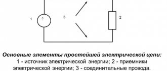
An electrical circuit is a collection of devices and elements designed for the flow of electric current.
Any electrical circuit contains:
1) current source
, creating the necessary tension;
2) load
, that is, the device in which current needs to be created. The load can be a heater or an incandescent lamp, an electric motor or a bell, or various electrical household appliances.
The links in the chain are the connecting wires and the key.
, serving for convenience and safety of work.
As an example, consider a simple electrical circuit. It consists of a current source, a key that can open and close a circuit, a light bulb and connecting wires. The light comes on only when the key is closed.
Look again at the diagram of the electrical circuit. If you sketch it every time, the work will be too long and labor-intensive. Therefore, symbols were introduced for the main links of electrical circuits.
Drawings that show the connections of electrical devices in symbols are called diagrams.
In the figure you see a simple electrical circuit and its diagram. Compare them.
We have been talking about electric current for a long time, but we have not figured out what its direction is in an electrical circuit.
The direction of the electric current in the circuit is taken to be the direction in which positive charges move (or could move) in the conductor, i.e. from the positive pole of the source to the negative.
This agreement was accepted conditionally back in the nineteenth century, when the nature of electric current was not yet fully understood and it was believed that only positive charges could move.
Of course, after the discovery of the electron, which in most cases is a current carrier, it became clear that the choice was made unsuccessfully, but they did not change the old agreement.
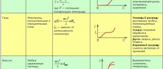
We already know that electric current can flow through various substances: metals, electrolytes, and, under certain conditions, through gases. As already mentioned, for an electric current to arise in any substance, it is necessary that there be charge carriers that can move under the influence of an electric field.
For example, in metals the carriers of free charges are electrons.
You know that all metals in the solid state have a certain crystalline structure.
Therefore, any metal must be considered as a spatial crystal lattice, in the nodes of which positive ions are located. In the space between the ions, free electrons move chaotically, the totality of which is called an electron gas.
Due to the random nature of the movement of electrons, electric charge transfer in any specific direction does not occur. But if an electric field is created inside the metal, then under the influence of its forces all free electrons will begin to move in an orderly manner in the direction of action of these forces.
However, it is wrong to think that the electrons will begin to move in a straight line. The trajectory of their movement will also remain complex due to interaction with other particles. The movement of electrons in this case resembles the drift of ice floes during ice drift, when they, moving randomly and colliding with each other, drift along the river flow.
Is it possible to directly verify experimentally that the electric current in a metal is a flow of electrons?
Of course you can. The idea of one such experiment is as follows. If you start rotating a piece of metal very quickly, the electron gas entrained by the crystal lattice will rotate with it (like a liquid in a rotating vessel). When a piece of metal suddenly stops, the electron gas must continue to move for some time by inertia, just as the liquid in a vessel continues to rotate after it has stopped. The challenge was to find a way to detect this inertial motion of electrons.
And it was solved in 1913 by Russian physicists Leonid Isaakovich Mandelstam and Nikolai Dmitrievich Papaleksi, as well as in 1916 by American scientists Richard Tolman and Thomas Stewart. The experiment was carried out as follows. A coil with a large number of turns of thin wire was driven into rapid rotation around its axis. The ends of the wire were connected through flexible conductors to a sensitive device - a galvanometer, which allows one to judge the presence of current.
When the coil was braked sharply for a fraction of a second, the galvanometer detected a current. Moreover, the direction of this current, and it was judged by the direction of deflection of the galvanometer needle, showed that it was caused by the movement of negatively charged particles, that is, electrons.
Thus, it was possible to prove that electric current in metals is the directed movement of electrons.
But the speed of this movement is small - only a few millimeters per second, which is hundreds of millions of times less than the average speed of thermal movement of electrons. Therefore, for example, in 2 hours of ordered motion, the electron will travel less than 5 m.
Although we know that as soon as we turn the switch, the lamp located a few meters away instantly lights up. Therefore, remember: the speed of current propagation and the speed of directional movement of electrons are not the same thing.
When they talk about the speed of current flow in a conductor, they mean the speed of propagation of the electric field inside the conductor
, which causes electrons to move in a directional direction. And it spreads at a speed of about 300,000 km/s, that is, at the speed of light.
We have something similar in the phenomenon of gas movement in gas pipelines. For example, when pressure rises at the Saratov end of the Moscow-Saratov gas pipeline, filled with gas, it spreads through the pipes at the speed of sound in gas (which is about 500 m/s) and is quickly transmitted to Moscow.
But the gas currently located near Saratov will reach Moscow much later, since the speed of its movement through the pipes is much less than the speed of pressure transmission.
Various types of current sources
The most common type is DC power supplies, which are of a chemical nature. These are batteries and accumulators. As a result of the chemical reactions occurring inside them, electrons from the outer shells of the atoms are torn off and moved to the negative terminal.
Therefore, it can be argued that current flows inside the accumulator or battery, and its movement is determined by the ongoing chemical processes. Typically, such current sources allow the use of relatively low voltages.
Energy sources can also be electromechanical. With their help, a fairly high voltage is obtained. Electromechanical devices produce electricity by performing mechanical work. This method has found wide application in industry.
The principle of operation of a thermal source of direct electric current is based on the phenomenon of heating. Under the influence of high temperature, an electromotive force arises at the point of contact of two metals or semiconductor structures. The higher the thermal energy consumption, the greater it will be. Electric current flows from the heated area to the cold one.
Thermoelectric sources are practically not used to power electrical equipment, since a small potential difference occurs in them. The main consumers of such electrical energy are temperature sensors.
The use of light sources in technology is becoming increasingly widespread. In such devices, electrons, under the influence of photons of light, receive additional energy and leave their atoms, forming an electric current. This environmentally friendly option for generating electricity is possible, for example, in desert areas where the weather is almost always sunny. It is advantageous to install a photovoltaic power source on the roofs of houses to provide citizens and organizations with electrical energy.
Power supplies. Classification and main characteristics
- Power supplies. Types, types, main characteristics.
- Drivers. Types, types, main characteristics.
QUESTION 1. A power supply unit is a device designed to provide power to an electrical appliance with electrical energy, subject to the requirements of its parameters: voltage, current, etc. by converting the energy of other power sources.
According to GOST R 52907–2008, the word “secondary” is omitted. The power supply can be integrated into the overall circuit (usually in simple devices; or when even a slight voltage drop on the supply wires is unacceptable - for example, a computer motherboard has built-in voltage converters to power the processor), made in the form of a module (power supply, power rack, etc.) ...), or even located in a separate room (power supply workshop).
Secondary power supply tasks
Ensuring power transmission - the power source must ensure the transmission of the specified power with minimal losses and compliance with the specified output characteristics without harm to itself. Usually the power of the power source is taken with some reserve.
Voltage waveform conversion – conversion of alternating voltage to direct voltage, and vice versa, as well as frequency conversion, generation of voltage pulses, etc. Most often, it is necessary to convert alternating voltage of industrial frequency to direct voltage.
Transformation of the voltage value - both increasing and decreasing. Often a set of several voltages of different sizes is needed to power different circuits.
Stabilization - voltage, current and other parameters at the output of the power source must lie within certain limits, depending on its purpose under the influence of a large number of destabilizing factors: changes in input voltage, load current, etc. Most often, voltage stabilization at the load is necessary, however, sometimes (for example, to charge batteries) current stabilization is necessary.
Protection - the voltage or load current in the event of a malfunction (for example, a short circuit) of any circuits may exceed permissible limits and damage the electrical device or the power source itself. Also, in many cases, protection is required against the passage of current along the wrong path: for example, the passage of current through the ground when a person or foreign object touches live parts.
Galvanic isolation of circuits is one of the measures to protect against the flow of current along the wrong path.
Adjustment - during operation, it may be necessary to change any parameters to ensure proper operation of the electrical appliance.
Control - may include adjustment, turning on/off any circuits, or the power source as a whole. It can be either direct (using controls on the device body), or remote, as well as programmatic (ensuring on/off, adjustment at a given time or with the occurrence of any events).
Control – display of parameters at the input and output of the power source, circuits on/off, protection activation. It can also be direct or remote.
Most often, secondary power supplies are faced with the task of converting electricity from an alternating current network of industrial frequency (for example, in Russia - 220 V 50 Hz, in the USA - 120 V 60 Hz).
The two most typical designs are transformer and switching mode power supplies.
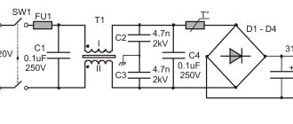
Transformer (network) power supply
Transformer power supply.
Circuit of the simplest transformer power supply without stabilization with a full-wave rectifier.
The classic power supply is a transformer power supply. In the general case, it consists of a step-down transformer or autotransformer, the primary winding of which is designed for mains voltage. Then a rectifier is installed that converts the alternating voltage into direct voltage (pulsating unidirectional). In most cases, the rectifier consists of one diode (half-wave rectifier) or four diodes forming a diode bridge (full-wave rectifier). Other circuits are sometimes used, such as in voltage-doubling rectifiers. After the rectifier, a filter is installed that smoothes out oscillations (pulsations). Usually it is simply a large capacitor.
Also, filters for high-frequency interference, surges (varistors), short-circuit protection, voltage and current stabilizers can be installed in the circuit.
Advantages and disadvantages
Advantages of transformer power supplies:
- Simplicity of design;
- Reliability;
- Availability of element base;
- Absence of generated radio interference (as opposed to pulsed interference, which creates interference due to harmonic components).
Disadvantages of transformer power supplies;
- Large weight and dimensions, proportional to power. Metal consumption;
- A trade-off between reduced efficiency and stability of the output voltage: to ensure stable voltage, a stabilizer is required, which introduces additional losses;
- Weak resistance of equipment with such a power supply to voltage surges and “zero burnout” (usually occurs in overhead networks in rural areas, leading to an increase in voltage in sockets from 220 to 380 V). Automation boards for heating boilers are notorious in this regard (as a rule, they are protected by a varistor, but often this is not enough). At the same time, equipment with switching power supplies (for example, modern TVs) often tolerate power increases up to 380 V without destruction.
Switching power supply
The simplest and brightest representative is a power supply for LED strips, modules, and so on with a supply voltage of 5,12,24 V. Contains a small number of parts, light, small. Dimensions 150 and weight grams are small. The same transformer power supply would weigh three kilograms, or even more. The power supply for LED strips also has a transformer, but it is small because it operates at a higher frequency. It should be noted that the efficiency of such a unit is about 70-80%, while it produces decent interference into the electrical network. There are many more units based on a similar principle - for laptops, printers, etc. So, the main advantage is small dimensions and light weight. Galvanic isolation is also present. The disadvantage is the same as that of its transformer counterpart. May burn out from overload!!! So if you are planning lighting on 12 V LED strips, for example, calculate the permissible load on each transformer.
It is advisable to create a 15–20% reserve. That is, if you have a 150 W transformer, it is better not to load more than 100 W of load on it. . It is also worth noting that pulse units do not like being turned on without a load. This is why it is not recommended to leave cell phone chargers in the outlet after charging is complete. However, everyone does this, which is why most current pulse units contain protection against switching on without load.
These two simple representatives of the power supply family perform a common task - providing the required voltage level to power the devices that are connected to them. As mentioned above, the devices themselves decide how much current they need. Advantages and disadvantages.
Advantages of switching power supplies:
- Comparable in output power with linear stabilizers, their corresponding switching stabilizers have the following main advantages;
- lighter weight due to the fact that with increasing frequency it is possible to use smaller transformers with the same transmitted power. The mass of linear stabilizers consists mainly of powerful, heavy low-frequency power transformers and powerful radiators of power elements operating in linear mode;
- significantly higher efficiency (up to 90-98%) due to the fact that the main losses in switching stabilizers are associated with transient processes at the moment of switching the key element. Since most of the time the key elements are in one of the stable states (that is, either on or off), energy losses are minimal;
- lower cost, thanks to the mass production of a unified element base and the development of high-power key transistors. In addition, it should be noted the significantly lower cost of pulse transformers with comparable transmitted power, and the possibility of using less powerful power elements, since their operating mode is key;
- reliability comparable to linear stabilizers. (Power supplies for computers, office equipment, and consumer electronics are almost exclusively pulsed; low-power linear power supplies are preserved only for powering low-current control boards for “white” household appliances such as washing machines, microwave ovens, heating boilers and speakers);
- wide range of supply voltage and frequency, unattainable for a comparable price linear one. In practice, this means the possibility of using the same switching power supply for wearable digital electronics in different countries of the world - Russia/USA/England, which are very different in voltage and frequency in standard sockets;
- the presence in most modern power supplies of built-in protection circuits from various unforeseen situations, for example from a short circuit and from lack of load at the output.
Disadvantages of switching power supplies:
- Operation of the main part of the circuit without galvanic isolation from the network, which, in particular, somewhat complicates the repair of such power supplies;
- Without exception, all switching power supplies are a source of high-frequency interference, since this is due to the very principle of their operation. Therefore, it is necessary to take additional noise suppression measures, which often do not eliminate the interference completely. In this regard, the use of pulsed power supplies for some types of equipment is often unacceptable;
- In distributed power systems: the effect of harmonics that are multiples of three. If there are effective power factor correctors and filters in the input circuits, this drawback is usually not relevant.
Our company uses switching step-down power supplies with an output voltage of 5.12, 24 Volts, open and waterproof, with a power of 5 W and above.
Power supply 36W 12V non-sealed perf.
Power supply 60W 12V sealed aluminum. IP67 housing
Power supply 15W 12V sealed aluminum. IP66 housing
QUESTION 2. In general, a driver is a current source for LEDs. There is usually no “output voltage” parameter for it. Only output current and power. However, you already know how you can determine the permissible output voltage - divide the power in watts by the current in amperes.
In practice this means the following. Let's say the driver parameters are as follows: current - 300 milliamps, power - 3 watts. Divide 3 by 0.3 - we get 10 volts. This is the maximum output voltage that the driver can provide. Let's assume that we have three LEDs, each of them is rated at 300 mA, and the voltage across the diode should be about 3 volts. If we connect one diode to our driver, then the voltage at its output will be 3 volts and the current will be 300 mA. Let's connect the second diode in series (see the example with lamps above) with the first - the output will be 6 volts 300 mA, connect the third - 9 volts 300 mA. If we connect the LEDs in parallel, then these 300 mA will be distributed approximately equally between them, that is, approximately 100 mA each. If we connect three-watt LEDs with an operating current of 700 mA to a 300 mA driver, they will only receive 300 mA.
Under no circumstances will a working driver produce more current than it is designed for, no matter how you connect the diodes. It should be noted that there are drivers that are designed for any number of LEDs, as long as their total power does not exceed the driver power, and there are those that are designed for a certain number - 6 diodes, for example. However, they allow some smaller spread - you can connect five diodes or even four. The efficiency of universal drivers is worse than that of their counterparts designed for a fixed number of diodes due to some features of the operation of pulse circuits. Also, drivers with a fixed number of diodes usually contain protection against abnormal situations. If the driver is designed for 5 diodes, and you connected three, it is quite possible that the protection will work and the diodes will either not turn on or will blink, signaling an emergency mode. It should be noted that most drivers do not tolerate connection to the supply voltage well without a load - this is why they are very different from a conventional voltage source.
So, we have determined the difference between the power supply and the driver. Now let's look at the main types of drivers for LEDs, starting with the simplest ones.
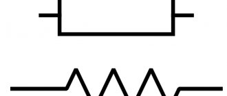
Resistor
This is the simplest driver for an LED. Looks like a barrel with two terminals. A resistor can be used to limit the current in a circuit by selecting the desired resistance. Disadvantage: low efficiency, lack of galvanic isolation. There are no ways to reliably power an LED from a 220 V network through a resistor, although many household switches use a similar circuit.
Capacitor circuit
Similar to a resistor circuit. The disadvantages are the same. It is possible to produce a capacitor circuit of sufficient reliability, but the cost and complexity of the circuit will increase greatly.
Driver with low voltage input
This category includes drivers designed to connect to a primary voltage source - a power supply or battery. For example, these are drivers for LED flashlights or lamps designed to replace 12 V halogen ones. The advantage is small size and weight, high efficiency, reliability, and safety during operation. Disadvantage: A primary voltage source is required.
Network driver
Completely ready to use and contain all the necessary elements to power the LEDs. The advantage is high efficiency, reliability, galvanic isolation, safety during operation. The disadvantage is the high cost. They can be either in a case or without a case.
Using drivers in practice
It is necessary to take into account the features of LEDs, namely the voltage drop across them. For example, a red 1 W LED has an operating current of 300 mA and a voltage drop of 1.8-2 V. Its power consumption will be 0.3 x 2 = 0.6 W. But a blue or white LED has a voltage drop of 3-3.4 V at the same current, that is, a power of 1 W. Therefore, a driver with a current of 300 mA and a power of 10 W will “pull” 10 white or 15 red LEDs. The difference is significant. A typical diagram for connecting 1 W LEDs to a driver with an output current of 300 mA looks like this:
The lamps produced by the company use mainly 300-330mA drivers, both open and sealed.
Driver for LEDs 18-25*1 IP40 220 V PF>0.9 300mA
Driver for LEDs 5-10*1 open 220 V 300mA
Driver for LEDs 18-25*1 IP65 220 V PF>0.9 300mA
How do chemical sources work?
Such sources can be divided into two types:
- Galvanic, the operating principle of which is based on the use of electrolytic reactions.
- Rechargeable, capable of being recharged using electrical energy.
Galvanic ones are also called primary sources, and battery ones are called secondary sources. The principle of operation of the former is based on the presence of an electrical composition in which the terminals are immersed. The chemical processes occurring here ensure the movement of electrons in such a way that there is always a shortage of electrons at one terminal, and an excess of them at the second.
Galvanic devices do not require the use of an additional energy source for charging. The disadvantage of galvanic current sources is that during their operation, irreversible chemical reactions occur, which gradually reduce the efficiency of the battery, and ultimately lead to the cessation of its functioning.
The terminal with a positive charge is usually called the cathode, and the terminal with a negative charge is called the anode. The first is usually made of cadmium, lead, zinc. For the second, graphite, manganese oxide, nickel hydroxide or lead oxide are used.
There are different types of voltaic batteries. Their name is determined by the electrolyte used. Mainly used:
- Lithium.
- Alkaline.
- Salt ones, which are also called dry ones.
Batteries of the second and third types consist of a graffito-manganese rod, which is the cathode. It is located inside a zinc cup that acts as an anode. The gap between them is filled with electrolyte.
It is important to note that the latter is not a liquid, but a paste. Alkaline batteries use potassium hydroxide, while salt batteries use a paste made from ammonium chloride.
The cathode of a lithium battery is made of lithium derivatives on aluminum foil, and the anode is made of graphite on copper foil. Between them there is a porous separator impregnated with electrolyte and performing the functions of a conductor.
The operating cycle of a battery, unlike a battery, is that during the charging process under the influence of electrical energy, chemical reactions occur that ensure the accumulation of charges at the terminals. That is, first electrical energy is converted into chemical energy, and then the latter is converted back into electrical energy.
However, such transformations are not permanent; they gradually reduce the efficiency of the power supply. Over time, the potential obtained at the terminals during recharging becomes smaller, and the discharge time becomes shorter. The presence of the memory effect significantly reduces the efficiency of using the energy source.
The memory effect manifests itself as follows: if charging occurs to the maximum value and discharging to zero, then its influence is minimal. If the battery is started to be used without being fully charged, it remembers the last value and subsequently considers it the maximum. With subsequent recharges, the battery will no longer exceed it.
The most common types of batteries are:
- Lithium-ion.
- Alkaline nickel-cadmium.
- Lead-acid.
Each variety listed here has a corresponding designation on its body, as well as its own strengths and weaknesses.
Lead-acid or nickel-cadmium batteries are usually mounted as a unit. In this case, the cathode of the previous element is connected to the anode of the next one. As a result, the consumer receives a total potential difference.
Lithium-ion batteries are more popular due to their ability to be recharged multiple times with virtually no memory effect.
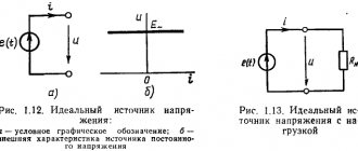
EMF source and current source
When analyzing electrical circuits, the concept of an ideal element is often used, that is, an element in which only one parameter is concentrated, in contrast to a real element in which, in addition to one main parameter, there are parasitic parameters. For example, a resistor can be thought of as an ideal resistance, but in a real resistor there is both capacitance (for example, between the terminals) and inductance (in a wirewound resistor, which uses wire wound on a ceramic frame). That is, ideal elements are used to simplify the analysis of an electrical circuit.
Energy sources in electrical circuits are also simplified when analyzing circuits; in addition, they are divided into two types: EMF sources and current sources. Let's consider each of them separately.
An ideal EMF source is characterized by the fact that the voltage at its terminals does not depend on the current flowing through it, that is, there are no passive elements inside such an EMF source (resistance R, inductance L, capacitance C), and therefore there is no voltage drop across the passive elements.
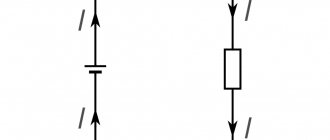
Thus, the voltage at its terminals is equal to the EMF, and the current is theoretically unlimited, that is, if its output terminals are closed, the electric current should be infinitely large. Therefore, an ideal EMF source can be considered as a source of infinite power. However, in reality, the current has a finite value, since the voltage drop across the internal resistance when the terminals are short-circuited balances the source emf. Thus, a real EMF source can be depicted as an ideal EMF source with a passive element connected in series, which limits the power supplied to the external circuit.
EMF sources: ideal (left) and real (right).
An ideal current source is characterized by the fact that the current flowing through it does not depend on the voltage that is present at its terminals, that is, the resistance inside the current source is infinitely large and therefore the parameters of the external elements of the electrical circuit do not affect the current flowing through the source.
Thus, with an infinite increase in resistance, the voltage at the terminals of an ideal current source also increases, and therefore the power increases to infinity, that is, a source of infinite power is obtained. Since in reality the power is still finite, the real current source is depicted as an ideal current source with a parallel connected passive component that characterizes the internal parameters of the current source and limits the power supplied to the external circuit.
Current sources: ideal (left) and real (right).
Mechanical sources
When using them, current is generated using generators. Mechanical energy ensures its rotation, and the changing energy of the magnetic current ensures the formation of alternating current. To obtain constant voltage, you need to use rectifiers. Such devices are built on various circuits. Rectifiers can be half-wave or full-wave.
In the first case, the incoming current, which has a sinusoidal shape, is converted in such a way that only positive pulses remain and negative pulses disappear. In the second, the positive ones remain in place, and the negative ones change polarity. In the latter case, energy conversion occurs more efficiently.
A rectifier circuit including an input transformer provides lower ripple. Such variants of devices are called linear.
Pulse circuits are also used for rectification. First, a signal with a pulse frequency of 15–60 kHz is obtained from alternating voltage, which is then converted to direct current.
The latter option allows you to create a more compact circuit. The use of such devices is becoming increasingly widespread in modern electrical engineering.
Sources of electric current, invention of the electric machine
Field-effect transistor current stabilizer circuit
Generating electricity using generators is the main direction in electricity production. Mechanical sources are divided into two types of generators:
- machines generating direct current;
- generators that produce alternating current.
Sources of alternating current and direct current are generators that convert mechanical rotational energy into electrical energy. A statement by Emil Lenz, a Russian scientist, in 1833 provided the impetus for work on the creation of generators. Lenz announced the possible reciprocity of magnetoelectric phenomena. This meant that DC and AC motors could not only rotate when a voltage of the appropriate nature was applied, but also begin to produce this voltage when rotating.