Rules for using the calculator
In everyday life, we are usually interested in four interrelated characteristics of electricity:
- voltage;
- current;
- resistance;
- or power.
If you know two quantities included in Ohm’s law (U, R, I), then enter them in the appropriate lines, and the remaining parameter and power will be calculated automatically.
Be careful to avoid mistakes.
All values must be filled out in the same dimension : amperes, volts, ohms, watts without using fractional or multiplicity symbols.
A visual table will help you navigate to them.
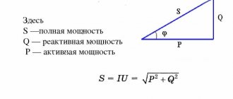
Purpose and definition of impedance
Almost no electronic device can operate without resistors in its circuit. Being passive elements, their main purpose is to limit the amount of current in an electrical circuit. In addition to current limiting, they serve as voltage dividers or shunts in measuring instruments.
Electrical resistance is a quantity that has a physical nature and characterizes the ability of a conductor to pass electric current. The principle of operation of a resistor was described by the outstanding experimenter Ohm. Later, the unit of measurement of electrical resistance - Ohm - was named in his honor. The scientist, conducting a series of experiments, established the relationship between current strength, voltage and resistance in the conductor. As a result, a simple formula was derived known as Ohm's law: I = U/R, where:
- I is the current passing through the conductor, measured in Amperes;
- U is the voltage applied to the conductor, unit of measurement is Volt;
- R is the conductor resistance, measured in Ohms.
Later, devices used only as resistance elements in electrical circuits were called resistors. Such devices, in addition to the resistance value, are characterized by power, calculated using the following formula: P = I2 * R. The resulting value is measured in Watts.
The circuit design uses both parallel and series connections of conductors. Depending on this, the impedance of the circuit section also changes. The type of connection, if it is not used to select the desired value, precisely characterizes the use of resistors in the first case as current limiters, and in the second - as voltage dividers.
In the diagrams, resistors are indicated in the form of a rectangle and signed with the Latin letter R. The serial number and resistance value are indicated next to it. For example, R23 1k means that resistor number 23 has a resistance of one kiloohm. The stripes shown inside the rectangle characterize the power dissipated on the conductor.
The fundamental law of conservation of energy says: energy does not disappear anywhere and does not appear from anywhere, but only changes shape. Therefore, when the current is limited, part of the energy is transformed into heat. It is this part that is called the dissipation power of the resistor, i.e. its value that the resistance can withstand without changing its parameters.
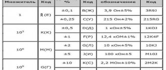
The resistor itself can have a different design and appearance . For example, be wire, ceramic, mica, etc. It is marked in three ways:
- Color stripe system. Each strip is responsible for a certain multiplier. The interpretation of the strips can be taken from reference books or online calculators.
- Numbers and letters. The number directly indicates the resistance value, and the letter indicates the multiplier. For example, 15M is fifteen megaohms.
- Digital. Usually three digits are used, the first and second indicate the resistance value, and the last is the multiplier. For example, 103 is ten kiloohms.
Therefore, seeing what resistors are installed in the circuit, even a novice radio amateur will not have difficulty calculating the total resistance, especially using an online calculator for parallel or series connection of resistors. If it is impossible to distinguish the markings on the housing, its resistance can be measured with a multimeter. But experienced electrical engineers know that for an accurate measurement, one resistance terminal will need to be disconnected from the circuit. This is due precisely to the type of conductor connection.
Simple calculation examples
Household AC network
Example No. 1. Checking the heating element.
The washing machine has a built-in tubular electric heater 1.25 kW at 220 volts. It is necessary to check its serviceability by measuring the resistance. Based on power, we calculate current and resistance.
I = 1250 / 220 = 5.68 A; R = 220 / 5.68 = 38.7 Ohms.
We check the resistance calculation using a current and voltage calculator. The data matched. You can begin electrical measurements.
Example No. 2. Checking motor resistance
Let's say that we bought a 1.6 kilowatt washing vacuum cleaner for cleaning premises. We are interested in its current consumption and the resistance of the electric motor in operating condition. We count the current:
I = 1600 / 220 = 7.3 A.
We enter into the columns of the calculator a voltage of 220 volts and a current of 7.3 amperes. Let's start the calculation. We will automatically receive the data:
- motor resistance - 30.1 Ohm;
- power 1600 watts.
DC circuits
Let's calculate the filament resistance of a 55-watt halogen light bulb installed in a 12-volt car headlight.
We count the current:
I = 55 / 12 = 4.6 A.
We enter 12 volts and 4.6 amperes into the calculator. It calculates:
- resistance 2.6 ohms.
- power 5 watts.
Here I would like to draw your attention to the fact that if you measure the resistance in a cold state with a multimeter, it will be significantly lower.
This property of metals makes it possible to create simple and relatively cheap incandescent lamps without the complex ballasts required for LED and fluorescent lamps.
In other words: a change in the resistance of tungsten when heated to a red-hot state limits the increase in current through it. But when the metal is cold, an inrush of current occurs. It can cause the thread to burn out.
To extend the service life of such light bulbs, a gradual, smooth supply of voltage from zero to the nominal value is used.
As simple but reliable devices for cars, a current limiting relay circuit operating in steps is often used.
When the switch SA is turned on, the resistance of the resistor R limits the inrush of current through the cold filament. When it warms up, due to a change in the voltage drop across the HL1 lamp, the electromagnet with the relay winding KL1 will put its contact on hold.
It will bypass the resistor, which will render it unusable. The rated current of the circuit will flow through the filament.
Where is the current divider used?
The current divider is very common in electrical engineering. It is important not to confuse a current divider with a voltage divider, since after analyzing publicly available sources, conflicting information was revealed even on Wikipedia.
Quoting from Wikipedia: “A current divider is important in circuit design as a circuit element for connecting a device with a rated current less than that flowing in the circuit.” Quoting from another source: “When designing electrical circuits, cases arise when a current of the same rating flows in the circuit, but the rated permissible load current must be less. For these purposes, current dividers are used.” And here’s what all this leads to - quoting another electrical engineering blog: “Simply put, if instead of one of the resistors we connect, for example, a fan, then by changing the resistance of the second resistor, we will also change the current strength, and therefore the power passing through the fan. »
It is important to understand that the voltage throughout the entire circuit is the same for each resistor. And the current strength in the resistor section depends only on its resistance. Therefore, if we consider the fan example, by changing the resistance of another resistor, we cannot change the amount of current passing through the fan. The power will remain the same. To change the current and, accordingly, power, a load must be connected in series with the fan, and not in parallel. A series connection is a voltage divider. A parallel connection is a current divider. The information from Wikipedia can hardly be called incorrect, but it is not complete. There is not enough clarification that to connect a device with a rated current less than that flowing in the circuit, you need to combine a current divider with a voltage divider.
Let's return to examples of using a current divider. Current divider circuits are used in measurement circuits where a portion of the current being measured is required to pass through a sensitive device. Using the current divider formula, you can select a suitable shunt resistor so that exactly the specified proportion of the total current always passes through the measuring device:
Now let's turn to examples of a current divider, which are literally next to each one. Any private house or apartment is a parallel connection, and therefore a current divider. The set of all repeated neutral grounding conductors of the transformer is also a current divider. And not the most pleasant example of a parallel connection is a situation when the current simultaneously flows through the ground electrode and the person who touched the body of the grounded electrical appliance. In this case, a ground electrode with a small resistance in addition to a large human resistance gives a total low resistance. You don’t even have to count, but simply use one of the rules - the total resistance is always less than the resistance of any resistor connected in parallel. And here it is important to understand that the current, passing through this grounding-person connection, then on its way encounters another resistance - for example, from the neutral grounding conductor of a transformer. The result is a voltage divider, which, together with the current divider, is the basis for the safety of using grounding. That is, there is a voltage drop across each ground electrode. And the lower the voltage, the lower the current.
Useful information for a novice electrician
How to use Ohm's law in practice
Almost two centuries ago, back in 1827, through his experiments, Georg Ohm revealed a pattern between the main characteristics of electricity.
He studied and published the effect of the resistance of a section of a circuit on the amount of current produced under the influence of voltage. It is convenient to present it with a visual picture.
Any work is always created by an electric current. It rotates the rotor of an electric motor, causes a light bulb to glow, welds or cuts metals, and performs other actions.
Therefore, he needs to create optimal conditions: the magnitude of the electric current must be maintained at the nominal level. It depends on:
- the voltage applied to the circuit;
- resistance of the medium through which the current flows.
Here, voltage, as the potential difference of applied energy, is the force that creates electric current.
If there is no voltage, then no useful work will occur from the connected electrical circuit due to the lack of current. This situation often occurs when the supply wire is broken, broken, or burnt out.
Resistance solves the inverse problem for voltage. At a very large value, it limits the current so much that it is unable to do any work. This mode is used for good dielectrics.
Online current divider calculator
The presented online calculator allows you to calculate the current strength when using series resistive dividers on any part of the circuit. For the calculation, it is necessary to enter the total current of the circuit and the resistance values of the resistors in the parallel section. The current divider calculator supports up to 10 resistors at a time.
Resistor current divider calculator:
| Source current strength, A | |
| Resistor | Current strength in the resistor section, A |
Definition
If you calculate the total resistance (Rtotal), you can find out the change in the main electrical parameters (current (I) and voltage (U)) when the circuit is connected to a specific power source. In the simplest version, it is enough to apply Ohm's law (I = U/R) and neglect the internal resistance of the battery.
At a voltage of U = 6.5 V, a current of I = 6.5/20 = 0.325 A will flow through the connected resistor R = 20 OM. Using the calculated parameter, you can find out the power using the classical formula:
P = I2 *R = U2/ R = 0.105625 * 20 = 2.11 W.
The resulting value will be useful for choosing a suitable passive element in the store’s assortment.
In practice, we have to solve problems with a large number of elements. The overall indicator is equivalent to the total resistance of the circuit. However, simple addition cannot obtain the correct result. Below are the technologies that perform correct calculations.
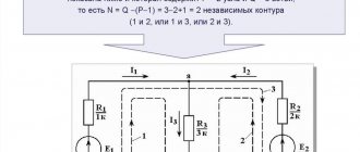
The figure explains the terminology used:
- i1, i2… i6 – currents in individual circuits;
- R1-R3 – passive elements (resistors);
- e1, e2 – typical designations of current sources (EMF);
- L and C – components with reactive characteristics (inductive and capacitive, respectively);
- branches are called with one current;
- the places where these chains are connected are nodes;
- the contours (indicated by Roman numerals I, II and III) show closed current paths along several branches.
How to determine equivalent resistance
If there are several resistive sources in the electrical network, then in order to calculate the current, voltage and power, one interchangeable physical indicator of the resistance of the electrical circuit should be used.
Any serial or parallel connection can be converted using an equivalent resistor and one source of electromotive force. The resistance in this case will be equal to the sum of all the obstacles of passive devices to the charge of the electrical network. The electromotive force of an interchangeable source will be equal to the sum of all sources that are included in the circuit.
Formula for determining the indicator
Note! By folding the circuit, using transformations of series-connected or parallel conductor devices, you can make further calculations in any circuit as simple as possible. The exception will be circuits that contain resistance in the form of a star and triangle.
What is the equivalent resistance of resistors
There is no exact concept in physics. It can be derived through a number of other terms and the formulation of Ohm's law. As a result, it turns out that the equivalent resistance of the resistors is the total obstacle of the interchangeable passive elements of the electrical network so that the charge passes into the conductor.
Resistor resistance
For your information! One indicator gives the output resistance value without the influence of a number of extraneous moments on it.
Detailed explanation of equivalent resistance
Parallel connection
This connection of resistors is obtained by combining two or more electrical devices, in which some of their terminals are connected to each other and form the first common point, and the others, similar to the first, form the second common point. In this case, the voltage on all elements is the same, and the passing current depends on their impedance.
The formula for parallel connection of resistors is as follows:
What kind of lighting do you prefer?
Built-in Chandelier
R = (R1*R2*R3…*Rх) / (R1+R2+R3…+Rх), where Rх is the serial number of the resistor.
It follows that the current flowing through each conductor is found by the formula: In = U/Rn.
Based on this, when connected in parallel, the resulting impedance of two or more resistors will be less than the smallest resistance value in the connection. Moreover, when only two resistors of the same rating are connected in parallel, they can be replaced with an equivalent equal to one-half of the value of this rating.
This way you can connect a hundred resistors, then the equivalent resistance is determined as a hundredth of the nominal value. For example, let there be a section of the circuit with ten resistors connected in parallel to each other with a nominal value of each equal to 10 Ohms, then the total resistance will be a tenth, namely Rob = 10/10 = 1 Ohm.
It is important to note that with such a connection the current value will be divided by each element, therefore resistors can be used with less power than if an equivalent was used that replaces the entire parallel connection.
Example of replacement selection
When developing the device, there was a need to use a resistor with a resistance of 6 ohms in a section of the circuit. When studying the nominal range of standard values produced by industry, it can be noted that there is no 6 Ohm resistor in it.
To obtain the desired value, you will need to use the parallel inclusion of two elements. The equivalent resistance value for the two resistors in this case is in the following order:
- 1/R = (1/R1) + (1/R2);
- 1/R = (R1+R2) / (R1*R2);
- Re = (R1*R2) / (R1+R2).
From the solution it is clear that if R1 is the same as R2, then the total resistance value is equal to half the value of one of the elements. Therefore, with the required nominal value of 6 Ohms, this value will be: Rx = 2*6 = 12 Ohms. To check the result, you should substitute the received answer into the formula: Re = (R1*R2) / (R1+R2) = (12*12) / (12+12) = 6 Ohm.
Thus, the solution to the problem will be the parallel connection of two resistors with a resistance value of 12 ohms.
Equivalent problem
Let there be a circuit with three resistors connected in parallel, and to simplify it it is necessary to replace them with one element. The conductor ratings are: R1 = 320 Ohm, R2 = 10 Ohm, R3 = 1 kOhm. To solve the problem, the already known formula is used:
- 1/R = (1/R1) + (1/R2) + (1/R3);
- Req = (R1*R2*R3) / (R1+R2+R3).
Before substituting quantities into the formula , they will all need to be converted to the International System of Units (SI). So, one kiloOhm is equal to 1000 Ohms; when you substitute this value, you get the answer: Re = (320*1*1000) / (320+10+1000) = 2406 Ohms or 2.4 kOhms, which exactly corresponds to the value from the standard series. This calculation method is used for any number of resistors connected in parallel.
Color coding of resistors with five and six stripes online calculation
Resistor calculator with five color stripes:
To determine the resistance of six-band resistors, you need to use a five-band element calculator and take into account the sixth color band, which represents the temperature coefficient of resistance. A detailed table of temperature coefficient of resistance (TCR) values and their relationship to a specific color is given in the following table:
| Color | TKS (ppm/ºC) |
| Brown | 100 |
| Red | 50 |
| Yellow | 25 |
| Orange | 15 |
| Blue | 10 |
| Violet | 5 |
| White | 1 |
Mixed connection
In this case, a combination of parallel and sequential connection of elements is used in a section of the circuit. This connection is often called parallel-serial:
- When connected in series, the total impedance of the elements is directly proportional to the sum of the resistances of each resistor.
- When connecting conductors in parallel, the reciprocal of the sum of the circuit impedance corresponds to the sum of the reciprocal of the resistances of the elements connected in parallel.
Using these rules, which are valid for any number of connected conductors in the circuit, the overall impedance value for any type of connection is determined. In order to determine the equivalent value of the resistance of a parallel-series connection, a section of the circuit is divided into small groups of parallel or series resistors. Then an algorithm is used to help optimally calculate the equivalent value:
The total resistance of all nodes in a circuit with parallel connection of resistors is determined:
- When there are series-connected conductors in these nodes, their resistance is initially calculated.
- Once the equivalent values have been calculated, the circuit is simplified to a series chain of equivalent resistors.
- The final value of the total resistance is found.
For example, there is a circuit in which it is necessary to determine the total resistance of the circuit, with the resistance of the resistors R1 = R3 = R5 = R6 = 3 Ohms, and R2 = 20 Ohms and R4 = 24 Ohms. Resistances R3, R4, and R5 are connected in series, so the total impedance in this section of the circuit is equal to: Rob1 = R3+R4+R5 = 30 Ohms.
After replacing R3, R4, R5 with Rob1, resistor R3 will be connected in parallel with this resistance. Therefore, the impedance in this section will be equal to:
Rob2 = (R2* Rob1) / (R3+Rob1) = (20*30) / (20+30) = 12 Ohm.
Resistors R1 and R6 are connected in series with Rob2, which means that the equivalent of the entire circuit is equal to: Req = Rob1+Rob2+ R6 = 3+12+3 = 18 Ohms.
So, step by step, the equivalent value of any circuit complexity is calculated . With many conductors included in an electrical circuit, it is easy to make mistakes in calculations, so all operations are performed carefully or online calculators are used.